EP0546495A2 - Fixier-Heizelement und Verfahren zu dessen Herstellung - Google Patents
Fixier-Heizelement und Verfahren zu dessen Herstellung Download PDFInfo
- Publication number
- EP0546495A2 EP0546495A2 EP19920120888 EP92120888A EP0546495A2 EP 0546495 A2 EP0546495 A2 EP 0546495A2 EP 19920120888 EP19920120888 EP 19920120888 EP 92120888 A EP92120888 A EP 92120888A EP 0546495 A2 EP0546495 A2 EP 0546495A2
- Authority
- EP
- European Patent Office
- Prior art keywords
- heat generating
- generating member
- fixing heater
- trimmed
- substrate
- Prior art date
- Legal status (The legal status is an assumption and is not a legal conclusion. Google has not performed a legal analysis and makes no representation as to the accuracy of the status listed.)
- Granted
Links
Images


Classifications
-
- H—ELECTRICITY
- H05—ELECTRIC TECHNIQUES NOT OTHERWISE PROVIDED FOR
- H05B—ELECTRIC HEATING; ELECTRIC LIGHT SOURCES NOT OTHERWISE PROVIDED FOR; CIRCUIT ARRANGEMENTS FOR ELECTRIC LIGHT SOURCES, IN GENERAL
- H05B3/00—Ohmic-resistance heating
- H05B3/10—Heating elements characterised by the composition or nature of the materials or by the arrangement of the conductor
- H05B3/16—Heating elements characterised by the composition or nature of the materials or by the arrangement of the conductor the conductor being mounted on an insulating base
-
- G—PHYSICS
- G03—PHOTOGRAPHY; CINEMATOGRAPHY; ANALOGOUS TECHNIQUES USING WAVES OTHER THAN OPTICAL WAVES; ELECTROGRAPHY; HOLOGRAPHY
- G03G—ELECTROGRAPHY; ELECTROPHOTOGRAPHY; MAGNETOGRAPHY
- G03G15/00—Apparatus for electrographic processes using a charge pattern
- G03G15/20—Apparatus for electrographic processes using a charge pattern for fixing, e.g. by using heat
- G03G15/2003—Apparatus for electrographic processes using a charge pattern for fixing, e.g. by using heat using heat
Definitions
- the present invention relates to a fixing heater used for fixing toner image in a copying machine, for example, and also relates to a method of manufacturing the same.
- a fixing heater used for fixing toner image in a copying machine is produced by applying a paste of, for example, a silver-palladium alloy powder on the surface of an elongated substrate such as ceramics as shown in Fig. 9 and then firing the applied paste.
- a uniform temperature application is generally required such as of 200 °C with less allowance of about 10 ° C.
- a resistance value of a film-like heat generating member 2 is adjusted to fall within a predetermined range so as to obtain a constant heat generation rate when a predetermined level of electrical current is applied.
- such adjustment of the resistance value has been done by varying a sheet resistance value of the heat generating member 2 by varying the amount of the conductive paste constituting the material of the heat generating member 2 and being printed to a substrate 1, i.e. the size of the heat generating member or by selecting the material of the conductive paste.
- the resistance adjustment method has to be performed before the firing for the print of the heat generating member.
- it has not been allowed to effect a fine readjustment after the firing, which makes it difficult to obtain a desired resistance value and, hence, causes a large variation or fluctuation of a generated temperature of a fixing heater as a product.
- a resistor is printed in a manner used in ordinary hybrid ICs (integrated curcuits) and the resistor as the heat resisting member 2 is then subjected to trimming so as to provide a key-like shape by using a laser, for example.
- a mere application of the laser trimming treatment to the fixing heater produces a temperature distribution as shown in Fig. 10B in which heat generation is locally increased at the trimmed portion, resulting in a cause of non-uniform fixing.
- such conventional technology is not available for fixing the toner image in a copying machine.
- An object of the present invention is to substantially eliminate defects or drawbacks encountered in the prior art and to provide a fixing heater, particularly, for fixing toner image in a copying machine, for example, capable of obtaining a desired resistance value of the fixing heater and a desired distribution of the resistance value thereof, and also provide a method of manufacturing such fixing heater.
- Another object of the present invention is to provide a fixing heater, particularly, for fixing toner image in a copying machine, for example, capable of obtaining a desired distribution of a generated temperature of the fixing heater.
- a fixing heater comprising:
- the heat generating member is trimmed so as to provide the trimmed edge portion having partially different width along the direction, i.e. current flowing direction.
- a fixing heater comprising:
- Electrodes are further disposed in contact with end portions of the heat generating member.
- a method of manufacuring a fixing heater comprising the steps of:
- the method further comprises the step of further trimming the trimmed edge portion on the basis of an amount of resistance value change of the heat generating member before and after the former trimming step to obtain a predetermined resistance value.
- the method may further comprise the step of further triming the trimmed edge portion on the basis of an amount of resistance value change of the heat generating member during the former trimming step to obtain a predetermined distribution of the resistance value.
- the trimming steps are performed by means of laser beam.
- a fixing heater comprising:
- a fixing heater comprising:
- One of the pair of edge portions of the heat generating member is trimmed along the direction and the powder is formed of the material of the heat generating member fused and spattered by the laser-trimming treatment.
- a fixing heater comprising:
- the heat generating member of the film-like form is gradually trimmed along the edge of the heat generating portion of the heat generating member under the observation of the change of the resistance value, so that the fixing heater having a desired distribution of generated temperature can be obtained, thus precisely setting the generating temperature of the fixing hater as a product.
- the location of the temperature controlling portion to the heat generating member can enhance the desired distribution of the temperature.
- the thus manufactured fixing heater is particularly applicable for the fixing of the toner image in a copying machine, for example, in which substantially constant generated temperature distribution is highly required.
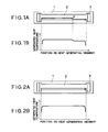
- Fig. 1A is a general view showing a construction of a fixing heater, and the fixing heater comprises a substrate 1 having an insulating property which is made of, for example, alumina A1 2 0 3 , a heat generating member 2 in form of a film disposed on a surface of the substrate 1 and electrodes 3 disposed to both ends of the heat generating member 2.
- the heat generating member 2 is formed by screen printing a paste containing powder of a silver-palladium alloy and then firing the same.
- the electrodes 3 are formed to both the longitudinal end portions of the film-like heat generating material 2 also by screen printing a paste containing highly conductive metal such as silver and then firing the paste.
- the heat generating member 2 is subjected to a laser-trimming treatment, as described hereinlater, in a direction of the flow of electrical current along an edge of the heat generating member 2 as indicated by an arrow in Fig. 1A.
- a laser-trimming treatment as described hereinlater, in a direction of the flow of electrical current along an edge of the heat generating member 2 as indicated by an arrow in Fig. 1A.
- one and the other ends of a heat generating portion of the heat generating member 2 are recognized by an ordinary image identification apparatus, for example, and then, one edge of the heat generating portion is trimmed by means of laser at a constant width in the direction of the current flowing, while measuring a rsistance value between the electrodes 3 by an ordinary device. This laser-trimming is repeated till the measured resistance value falls within a predetermined range.
- the fixing heater thus formed exhibits the desired resistance value since the adjustment of the resistance value is conducted after the printing and firing processes.
- the adjustment is conducted by the later-trimming effected along the edge of the heat generating member 2 in the current flowing direction, any substantial unevenness of the temperature distribution, attributable to the trimming, can be effectively avoided as shown in Fig. 1 B.
- the laser-trimming has been completed at a portion P between both the electrodes 3 attached to the heat generating member 2 as viewed in the current flow direction.
- This is only illustrative and the temperature distribution can be further made uniform by effecting evenly trimming the edge of the heat generating member 2 in the direction of flow of the electric current as shown in Fig. 2A.
- the trimming is effected at a constant width on one edge of the heat generating portion of the heat generating member 2 extending in the current flow direction from one end of the heat generating portion identified by an image recognizing device, for example, towards the other end thereof.
- the change in the resistance value is then detected by comparing the resistance value between the electrodes 3 as measured before the trimming and that as measured after the trimming.
- the width of the heat generating portion for the second trimming step is calculated by, for example, a computer on the basis of the change in the resistance value, and the second trimming is effected on the portion of the heat generating member 2 between the electrodes 3 on the basis of the calculated result so as to trim the heat generating member 2 from one end to the other end thereof in the current flow direction at the width determined by the calculation.
- a repeated durability tests were conducted on the fixing heater of the described embodiment by subjecting it to heat generating cycles each including continuous fifteen (15) seconds of power supply followed by five (5) second suspension of power supply. No abnormality was found in the heat generating performance even after more than 100,000 consecutive heating cycles, thus proving superiority of the fixing heater for the fixing of the toner image, for example, of the present invention.
- the heat generating member can have any other suitable form with its edge timmed in the current flow direction by means of, for example, laser beams.
- Fig. 3 shows another embodiment of the present invention, in which the fixing heater is further provided with a temperature controlling means for controlling the distribution of the temperature to be generated of the heat generating member 2.
- the heat generating member 2 has portions 4 having width reduced in the width direction thereof, the portions 4 being formed to the heat generating member 2 at the ends of another edge thereof, other than the edge to whcih the trimming is effected, near the electrodes 3.
- the location of the reduced width portions 4 of the heat generating member 2 serves to increase the heat generating amount at the end portions thereof at which the heat generation is likely lowered, thus improving the generated temperature distribution to be more uniform.
- the temperature controlling means such as portions 4 may be applied to the other portions along the other edge of the heat generating member 2 as occasion demands.
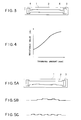
- one edge of the heat generating member 2 is trimmed throughout the longitudinal direction, i.e. current flowing direction, with a cut width of about 5% of the total width thereof, and thereafter, the change of the resistance value and the amount of the trimming are measured to thereby obtain the distribution of the resistance value between the electrodes 3 disposed at longitudinal end portions of the heat generating member 2, as shown in Fig. 4.
- the trimming may be further effected to increase the trimmed amount to compensate for a portion at which the change of the resistance value is small, that is, a portion having a low resistance value with respect to a unit area in view of the resistance value distribution. In this manner, the trimming amount is timely changed to thereby manufacture the fixing heater having a desired distribution of the resistance value.
- Fig. 5A shows a further embodiment of the fixing heater of the present invention, in which the laser-triming is first effected in uniformly along the current flowing direction to one edge of the heat generating member 2.
- a further laser-trimming may be carried out.
- Figs. 5B and 5C are examples of the trimmed shape of the edge portion by means of the laser, and the possibility of such shapes will be understood from the fact that the laser trimming is effected spot-likely as nature of the laser beam.
- the generated temperature distribution on the surface of the heat generating member 2 is amended from a state such as shown in Fig. 6A to a state shown in Fig. 6B showing the uniform distribution of the temperature to be generated after the trimming operation.
- Figs. 7A and 7B show a case in which the axially central portion of the fixing heater has a high temperature distribution and Fig. 7B shows a case in which the fixing heater has a waved temperature distribution along the axial direction thereof, i.e. the current flowing direction.
- Figs. 8A and 8B show still further enmbodi- ments of the fixing heaters according to the present invention, in which dust or powder like materials 5 adhere on the surface of the substrate 1 along the current flowing direction of the heat generating member 2 on the edge portion thereof as shown in Fig. 8A, and the materials 5 adhere on the edge portion of the heat generating member 2 along the full length of the heat generating portion thereof as shown in Fig. 8B.
- These mateials 5 are of the same substance as that froming the heat generating member 2 and are generally composed of the material of the heat generating member 2 fused during the laser trimming process.
- the described embodiments employs a paste containing a silver-palladium alloy as the material of the heat generating member, this is only illustrative and the paste may contain other metals such as nickel or tin.
- the electrode material also may be replaced with one of other metals which are widely used.
- another aspect of the fixing heater according to the present invention may be applied to a fixing heater having a surface covered by a glass layer.
- the glass layer is applied for the purpose of achiving a function to prevent abrasion of the heater due to rubbing by copy paper sheets which carry the toner and which move in contact with the surface of the fixing heater as well as a function to ensure the smooth sliding of the copy paper sheets and a function to ensure the electrical insulation thereby preventing leak of the electrical current flowing in a heat generating resistor.
- the cover glass for the known fixing heaters could not satisfactorily achieve these three functions. This is because no material for the cover glass which would satisfactorily perform these three functions has been available. In fact, no such cover glass material has been discovered up to now.
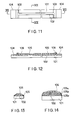
- a substrate 101 is made of a heat resistant alumina ceramics such as A1 2 0 3 andhas a rectangular tubular form of about 270mm length, 7mm width and 1 mm thickness.
- a heat generating resistor layer 102 is formed at a thickness of about 10 u m by applying and firing an electrically conductive paste on the substrate 101 in the longitudinal direction of the latter, the electrically conductive paste being a silver-palladium alloy (Ag/Pd) or a silver-palladium alloy containing ruthenium oxide (Ag/Pd + Ru0 2 ).
- the paradium contained in the alloy serves as a resistance element so that the resistance value of the heat generating resistor is determined by the content of palladium.
- the heat generating resistor has a resistance value of 34Q , and allows a current of 100V, thus generating heat of 300W. Both ends of the heat generating resistor 102 are wide-spread so as to provide electrode forming portions 103. Heat generated by the portion of the heat resistor layer 102 other than the electrode forming portions 103.
- An electrode layer 104 for connection to an external electrode is formed on the surface of the electrode forming portion 103 on each end of the heat generating resistor 102.
- the electrode layer 104 is provided for the purpose of obtaining contact electric resistance smaller than that of the heat generating resistance layer 102, and is formed form a paste of a metal such as silver (Ag), silver- platinum alloy (Ag/Pt), gold (Au) and platinum (Pt). That is, the above-mentioned metal paste is applied to and fired on each electrode forming portion (103), after formation of the whole heat generating resistor layer 102 including both terminal forming portions 103, thus obtaining the electrode layer 104 of about 10 ⁇ m thick on each end of the heat generating resistor layer 102.
- the surface of the web portion of the heat generating resistor layer 102 is coated by a glassy material having high electrical insulation power which forms an insulating glass layer 105.
- the insulating glass layer 105 is made of a material mainly composed of borosilicate glass, e.g., an insulating glass paste PLS 3310 produced by Nippon Denki Glass Co., Ltd., and is formed to have a thickness of about 10 ⁇ m by applying such a paste by printing followed by the firing.
- An insulating glass formed by using PLS 3310 when thickness is 35u m,exhibits an electrical insulation breakdown voltage as high as 2000 V under application of D.C. voltage.
- the insulating glass paste PLS 3310 is applied by printing after the formation of the heat generating resistor layer 102, followed by the firing.
- the insulating glass layer 105 is applied not only to the web portion of the heat generating resistor layer 103 but also to cover the boundary between the electrode layer 104 and the web protion. A large temperature gradient is developed in the boundary between the web protion and the electrode forming portion 103 of the heat generating layer 102, posing a large risk of cutting in this boundary portion of the heat generating resistor layer 102. In the illustrated embodiment, the above-mentioned risk is averted by the provision of the insulating glass layer 105 which covers the boundary region.
- the insulating glass layer 105 which covers the boundary region between the web portion of the heat generating resistor layer 104 and the electrode layer 103, is effective also in preventing exfoliation of the electrode layer which tends to occur at the boundary due to infuluence of heat.
- the surface of the insulating glass layer 105 is coated with a cover glass layer 106 made of a glassy material which has a low electrical insulation but exhibits a high degree of surface smoothness.
- the cover glass layer is made of a lead glass rich in lead oxide.
- a glass paste LS 207 produced by Tanaka Kinzoku International Co., Ltd. is glass layer of about 10u m thick.
- the glass paste LS 207 when the layer thickness is 35u m, exhibits a commparatively low level of electrical insulation breakdown voltage of 1500 to 1000 V under application of D.C. voltage, but has a surface smoothness Ra which is as small as 0.02 a m or less.
- the insulating glass layer 105 formed of PLS 3310 exhibits surface smoothness Ra of 1 to 2 ⁇ m.
- the insulating glass layer 105 cannot exhibit sufficiently high surface smoothness due to reasons such as inclusion of metal oxide fillers which are added for the purpose of enhancing electrical insulation power.
- the cover glass paste LS 207 is applied after the formation of the insulating glass layer 105, followed by the firing.
- the fixing heater having such construction has two types of glass layers, i.e., the insulating glass layer 105 and the cover glass layer 106, which are intended for different functions. Consequently, these glass layers can satisfactorily achieve the functions required for the glass layer. Namely, abrasion of the heat generating resistor 102 is prevented by these glass layers and, in addition, the insulating glass layer 105 provides sufficiently high electrical insulation effect while the cover glass layer 106 improves slide of the copy paper sheets. If the required electrical insulation is to be produced by the cover glass layer alone, the thickness of the cover layer will be increased, resulting in a reduction in the heat transfer of the heat generating resistor 102. Such problem is avoided in the describe embodiment of the fixing heater. The provision of the cover glass layer 106 on the insulating glass layer 105 eliminates the problem of inferior sliding of the copy paper which otherwise is unavoidable when the insulating glass layer 105 is used alone without being covered by the cover glass layer 106.
- the heat generating resistor layer 102, the insulating glass layer 105 and the cover glass layer 106 are successively formed, each employing application and firing of the paste, so that each glass layer can be formed without mixing together, thus ensuring that each layer performs its expected function.
- Fig. 14 is a sectional view of a second embodiment of the fixing heater in accordance with the present invention, corresponding to Fig. 13 illustrating the former embodiment.
- the insulating glass layer is composed of three layers 105a, 105b and 105c. Other portions are the same as those of the former embodiment and detailed description relating to such same portions is omitted.
- the same reference numerals are used in Fig. 14 to denote the same parts as those in Fig. 13.
- Each of the insulating glass layers 105a, 105b and 105c has the same glass composition as the first embodiment, and can be formed by the same method as that in the first embodiment. Namely, the insulating glass paste PLS 3310 is applied and fired to form each of the successive insulating glass layers.
- the fixing heater as described provides the same advantages as those offers by the former embodiment. Namely, the abrasion of the heat generating resistor layer 102 is prevented, while high electrical insulating breakdown voltage and high degree of slide of copy paper sheets are attained by the insulating glass layer 105 and the cover glass layer 106, respectively.
- the described method of producing fixing heater provides a higher level of electrical insulation breakdown voltage obtained with a given thickness of the insulating glass layer, due to the fact that the insulating glass layer is composed of a plurality of glass layers. Namely, since application and firing of the insulating glass layers are conducted a plurality of times, any pin hole which has been formed as a result of relief of gases during the firing of an underlying layer are covered by the paste of the next or overlying layer. Consequently, the final insulating glass layer composed of the laminate of glass layers has no pin hole which would extend throughtout the insulating glass layer, thus preventing leak of electrical current which would otherwise be caused due to the presence of pin holes, whereby the electrical insulation of the fixing heater is improved.
- the insulating glass layer provided sufficiently high electric insulation breakdown voltage, while the cover glass layer improved slide of the copy paper sheets.
- the heat generating resistor layer, the insulating glass layer and the cover glass layer are successively formed by applying and firing pastes, so that these layers can be formed without mixing each other, thus ensuring that each layer satisfactorily perform its own role.
Landscapes
- Physics & Mathematics (AREA)
- General Physics & Mathematics (AREA)
- Resistance Heating (AREA)
- Fixing For Electrophotography (AREA)
Applications Claiming Priority (6)
| Application Number | Priority Date | Filing Date | Title |
|---|---|---|---|
| JP324791/91 | 1991-12-09 | ||
| JP32479191 | 1991-12-09 | ||
| JP4132792A JP3129505B2 (ja) | 1992-02-27 | 1992-02-27 | 定着用加熱体、定着装置および画像形成装置 |
| JP41327/92 | 1992-02-27 | ||
| JP10873392A JPH05216360A (ja) | 1991-12-09 | 1992-03-31 | 定着ヒーター及びその製造方法 |
| JP108733/92 | 1992-03-31 |
Publications (3)
| Publication Number | Publication Date |
|---|---|
| EP0546495A2 true EP0546495A2 (de) | 1993-06-16 |
| EP0546495A3 EP0546495A3 (en) | 1993-08-11 |
| EP0546495B1 EP0546495B1 (de) | 1997-03-12 |
Family
ID=27290780
Family Applications (1)
| Application Number | Title | Priority Date | Filing Date |
|---|---|---|---|
| EP92120888A Expired - Lifetime EP0546495B1 (de) | 1991-12-09 | 1992-12-08 | Fixier-Heizelement und Verfahren zu dessen Herstellung |
Country Status (3)
| Country | Link |
|---|---|
| US (1) | US5587097A (de) |
| EP (1) | EP0546495B1 (de) |
| DE (1) | DE69218134T2 (de) |
Cited By (8)
| Publication number | Priority date | Publication date | Assignee | Title |
|---|---|---|---|---|
| US5874710A (en) * | 1992-12-29 | 1999-02-23 | Canon Kabushiki Kaisha | Fixing heater and fixing apparatus with trimmed resistive member |
| US5920757A (en) * | 1997-02-03 | 1999-07-06 | Canon Kabushiki Kaisha | Heater having an offset temperature detecting element and image heating apparatus having the heater |
| EP0766497A4 (de) * | 1995-03-28 | 1999-10-06 | Rohm Co Ltd | Heizvorrichtung für flachenformiges material |
| US6323460B1 (en) * | 1994-08-30 | 2001-11-27 | Canon Kabushiki Kaisha | Image heating apparatus in which first and second heating resistors are within a width of a nip through which a recording material passes |
| US6469279B1 (en) | 1996-03-07 | 2002-10-22 | Canon Kabushiki Kaisha | Image heating apparatus and heater |
| US6917014B2 (en) * | 2000-11-03 | 2005-07-12 | R. A. Jones & Co. Inc. | Sealing system for forming thermal seals and methods of operation thereof |
| WO2020210244A1 (en) * | 2019-04-08 | 2020-10-15 | Watlow Electric Manufacturing Company | Method to compensate for irregularities in a thermal system |
| WO2024017494A1 (en) * | 2022-07-19 | 2024-01-25 | Oerlikon Metco Ag, Wohlen | Electric heating element production method |
Families Citing this family (18)
| Publication number | Priority date | Publication date | Assignee | Title |
|---|---|---|---|---|
| JPH0968877A (ja) * | 1995-08-30 | 1997-03-11 | Canon Inc | 定着装置 |
| US6239411B1 (en) * | 1995-10-27 | 2001-05-29 | Minolta Co., Ltd. | Fixing device |
| DE19711522C2 (de) * | 1997-03-19 | 1999-11-18 | Josef Winter | Elektrisches Flächenheizelement, insbesondere für Spiegel |
| JP3729308B2 (ja) * | 1998-06-09 | 2005-12-21 | ローム株式会社 | ライン型加熱装置の構造 |
| US20030062358A1 (en) * | 2000-07-19 | 2003-04-03 | Atsushi Ito | Semiconductor manufacturing/testing ceramic heater |
| WO2002007195A1 (fr) * | 2000-07-19 | 2002-01-24 | Ibiden Co., Ltd. | Dispositif chauffant ceramique pour la fabrication/verification de semi-conducteurs, son procede de fabrication, et son systeme de fabrication |
| WO2002023600A1 (fr) * | 2000-09-13 | 2002-03-21 | Ibiden Co., Ltd. | Corps de chauffe en ceramique destine a la fabrication de semi-conducteurs et a un equipement d'inspection |
| US20040035846A1 (en) * | 2000-09-13 | 2004-02-26 | Yasuji Hiramatsu | Ceramic heater for semiconductor manufacturing and inspecting equipment |
| JP4837192B2 (ja) * | 2001-06-26 | 2011-12-14 | ローム株式会社 | 加熱ヒータおよびその加熱ヒータを備えた定着装置 |
| KR20050026904A (ko) * | 2001-09-10 | 2005-03-16 | 마이크로브리지 테크놀로지스 인크. | 저항기 트리밍 방법 |
| DE10162276C5 (de) * | 2001-12-19 | 2019-03-14 | Watlow Electric Manufacturing Co. | Rohrförmiger Durchlauferhitzer und Heizplatte sowie Verfahren zu deren Herstellung |
| DE602004011386T2 (de) * | 2003-11-20 | 2009-01-08 | Koninklijke Philips Electronics N.V. | Dünnschichtheizelement |
| US20050267664A1 (en) * | 2004-05-14 | 2005-12-01 | Jiyuan Ouyang | Method for adjusting a control signal of an electronic sensor |
| NL1027571C2 (nl) * | 2004-11-23 | 2006-05-24 | Ferro Techniek Holding Bv | Emailsamenstelling voor toepassing als dielektricum, en gebruik van een dergelijke emailsamenstelling. |
| WO2009111890A1 (en) * | 2008-03-14 | 2009-09-17 | Microbridge Technologies Inc. | A method of stabilizing thermal resistors |
| IT1402165B1 (it) | 2010-06-30 | 2013-08-28 | St Microelectronics Srl | Resistore ad elevata precisione e relativo metodo di calibratura |
| US9668302B2 (en) * | 2011-03-31 | 2017-05-30 | Kyocera Corporation | Ceramic heater |
| ITTO20120553A1 (it) | 2012-06-22 | 2013-12-23 | St Microelectronics Srl | Dispositivo a resistore calibrabile elettricamente e relativo metodo di calibrazione |
Family Cites Families (13)
| Publication number | Priority date | Publication date | Assignee | Title |
|---|---|---|---|---|
| US4374314A (en) * | 1981-08-17 | 1983-02-15 | Analog Devices, Inc. | Laser template trimming of circuit elements |
| US4403133A (en) * | 1981-12-02 | 1983-09-06 | Spectrol Electronics Corp. | Method of trimming a resistance element |
| US4772774A (en) * | 1987-06-02 | 1988-09-20 | Teradyne, Inc. | Laser trimming of electrical components |
| EP0295901B1 (de) * | 1987-06-16 | 1995-12-20 | Canon Kabushiki Kaisha | Bildfixiergerät |
| DE68921124T2 (de) * | 1988-08-25 | 1995-07-20 | Toshiba Lighting & Technology | Heizstreifen. |
| JPH02186585A (ja) * | 1988-11-22 | 1990-07-20 | Toshiba Lighting & Technol Corp | 加熱体 |
| JPH0632276B2 (ja) * | 1988-08-30 | 1994-04-27 | 東芝ライテック株式会社 | 加熱体 |
| US4897520A (en) * | 1988-10-31 | 1990-01-30 | American Telephone And Telegraph Company, At&T Technologies, Inc. | Laser debris vacuum scoop |
| US5083168A (en) * | 1988-11-15 | 1992-01-21 | Canon Kabushiki Kaisha | Fixing device and fixing heater for use in the same |
| US5171969A (en) * | 1989-10-30 | 1992-12-15 | Canon Kabushiki Kaisha | Movable film fixing device with heater control responsive to selected sheet size |
| JP2727734B2 (ja) * | 1990-04-26 | 1998-03-18 | 東芝ライテック株式会社 | トナー定着用ヒータ、定着装置および画像形成装置 |
| JPH048557A (ja) * | 1990-04-26 | 1992-01-13 | Toshiba Lighting & Technol Corp | ヒータ |
| JP2941962B2 (ja) * | 1991-01-08 | 1999-08-30 | キヤノン株式会社 | 定着装置 |
-
1992
- 1992-12-08 EP EP92120888A patent/EP0546495B1/de not_active Expired - Lifetime
- 1992-12-08 DE DE69218134T patent/DE69218134T2/de not_active Expired - Lifetime
-
1994
- 1994-07-13 US US08/274,367 patent/US5587097A/en not_active Expired - Lifetime
Cited By (11)
| Publication number | Priority date | Publication date | Assignee | Title |
|---|---|---|---|---|
| US5874710A (en) * | 1992-12-29 | 1999-02-23 | Canon Kabushiki Kaisha | Fixing heater and fixing apparatus with trimmed resistive member |
| EP0604977B1 (de) * | 1992-12-29 | 1999-04-07 | Canon Kabushiki Kaisha | Fixierheizelement und Fixiergerät mit abgeglichenem Widerstandselement |
| US6323460B1 (en) * | 1994-08-30 | 2001-11-27 | Canon Kabushiki Kaisha | Image heating apparatus in which first and second heating resistors are within a width of a nip through which a recording material passes |
| EP0766497A4 (de) * | 1995-03-28 | 1999-10-06 | Rohm Co Ltd | Heizvorrichtung für flachenformiges material |
| US6121589A (en) * | 1995-03-28 | 2000-09-19 | Rhom Co., Ltd. | Heating device for sheet material |
| US6469279B1 (en) | 1996-03-07 | 2002-10-22 | Canon Kabushiki Kaisha | Image heating apparatus and heater |
| US5920757A (en) * | 1997-02-03 | 1999-07-06 | Canon Kabushiki Kaisha | Heater having an offset temperature detecting element and image heating apparatus having the heater |
| US6917014B2 (en) * | 2000-11-03 | 2005-07-12 | R. A. Jones & Co. Inc. | Sealing system for forming thermal seals and methods of operation thereof |
| WO2020210244A1 (en) * | 2019-04-08 | 2020-10-15 | Watlow Electric Manufacturing Company | Method to compensate for irregularities in a thermal system |
| US11240881B2 (en) | 2019-04-08 | 2022-02-01 | Watlow Electric Manufacturing Company | Method of manufacturing and adjusting a resistive heater |
| WO2024017494A1 (en) * | 2022-07-19 | 2024-01-25 | Oerlikon Metco Ag, Wohlen | Electric heating element production method |
Also Published As
| Publication number | Publication date |
|---|---|
| EP0546495B1 (de) | 1997-03-12 |
| DE69218134T2 (de) | 1997-09-18 |
| US5587097A (en) | 1996-12-24 |
| EP0546495A3 (en) | 1993-08-11 |
| DE69218134D1 (de) | 1997-04-17 |
Similar Documents
| Publication | Publication Date | Title |
|---|---|---|
| EP0546495B1 (de) | Fixier-Heizelement und Verfahren zu dessen Herstellung | |
| US6734397B2 (en) | Heater having at least one cycle path resistor and image heating apparatus therein | |
| US6323460B1 (en) | Image heating apparatus in which first and second heating resistors are within a width of a nip through which a recording material passes | |
| DE69309369T2 (de) | Bildwärmefixiergerät und Heizvorrichtung | |
| KR20250116185A (ko) | 히터와, 그것을 구비하는 정착 장치, 화상 형성 장치 및 가열 장치 | |
| JP3284580B2 (ja) | ヒーター | |
| US5338919A (en) | Heater for sheet material and method for adjusting resistance of same | |
| US20250377617A1 (en) | Heater, fixing device, image formation device, and heating device | |
| JP2727734B2 (ja) | トナー定着用ヒータ、定着装置および画像形成装置 | |
| JP3582535B2 (ja) | 平面ヒータおよび定着装置 | |
| JP2740207B2 (ja) | 定着用加熱体、定着装置および事務用機器 | |
| US5321234A (en) | Linear heater | |
| JPH0259356A (ja) | 定着用加熱体、定着装置および画像形成装置 | |
| JPH05258843A (ja) | 定着ヒータ及びその製造方法 | |
| JP2923592B2 (ja) | 加熱ヒータおよびその製造方法 | |
| JPH0651658A (ja) | 定着用ヒータ、定着用ヒータの製造方法および定着方法ならびに定着装置 | |
| JPH0764418A (ja) | ヒータ、ヒータの通電方式、定着装置ならびに定着装置組込機器 | |
| JP3482000B2 (ja) | ヒータおよび定着装置ならびに定着装置組込機器 | |
| JPH0837083A (ja) | 定着用加熱体、定着装置および複写機 | |
| JPH06324584A (ja) | ヒータおよびヒータの製造方法ならびに定着装置 | |
| JPH08297431A (ja) | 定着ヒータ,定着装置および画像形成装置 | |
| JPH1048986A (ja) | 定着ローラ及び定着ローラの温度制御方法 | |
| JP2833659B2 (ja) | サーマルプリンターヘッド | |
| JPH05273880A (ja) | 加熱装置 | |
| JPH08227239A (ja) | 熱定着装置 |
Legal Events
| Date | Code | Title | Description |
|---|---|---|---|
| PUAI | Public reference made under article 153(3) epc to a published international application that has entered the european phase |
Free format text: ORIGINAL CODE: 0009012 |
|
| 17P | Request for examination filed |
Effective date: 19921208 |
|
| AK | Designated contracting states |
Kind code of ref document: A2 Designated state(s): DE GB |
|
| PUAL | Search report despatched |
Free format text: ORIGINAL CODE: 0009013 |
|
| AK | Designated contracting states |
Kind code of ref document: A3 Designated state(s): DE GB |
|
| RIN1 | Information on inventor provided before grant (corrected) |
Inventor name: SATO, SHIGEHIRO Inventor name: MATSUNAGA, YOSHIYUKI Inventor name: ONO, TSUYOSHI Inventor name: KARUBE, TAKAAKI |
|
| 17Q | First examination report despatched |
Effective date: 19950116 |
|
| GRAG | Despatch of communication of intention to grant |
Free format text: ORIGINAL CODE: EPIDOS AGRA |
|
| GRAH | Despatch of communication of intention to grant a patent |
Free format text: ORIGINAL CODE: EPIDOS IGRA |
|
| GRAH | Despatch of communication of intention to grant a patent |
Free format text: ORIGINAL CODE: EPIDOS IGRA |
|
| GRAA | (expected) grant |
Free format text: ORIGINAL CODE: 0009210 |
|
| AK | Designated contracting states |
Kind code of ref document: B1 Designated state(s): DE GB |
|
| REF | Corresponds to: |
Ref document number: 69218134 Country of ref document: DE Date of ref document: 19970417 |
|
| PLBE | No opposition filed within time limit |
Free format text: ORIGINAL CODE: 0009261 |
|
| STAA | Information on the status of an ep patent application or granted ep patent |
Free format text: STATUS: NO OPPOSITION FILED WITHIN TIME LIMIT |
|
| 26N | No opposition filed | ||
| REG | Reference to a national code |
Ref country code: GB Ref legal event code: 746 Effective date: 20010524 |
|
| REG | Reference to a national code |
Ref country code: GB Ref legal event code: IF02 |
|
| PGFP | Annual fee paid to national office [announced via postgrant information from national office to epo] |
Ref country code: GB Payment date: 20091202 Year of fee payment: 18 |
|
| PGFP | Annual fee paid to national office [announced via postgrant information from national office to epo] |
Ref country code: DE Payment date: 20091203 Year of fee payment: 18 |
|
| GBPC | Gb: european patent ceased through non-payment of renewal fee |
Effective date: 20101208 |
|
| REG | Reference to a national code |
Ref country code: DE Ref legal event code: R119 Ref document number: 69218134 Country of ref document: DE Effective date: 20110701 |
|
| PG25 | Lapsed in a contracting state [announced via postgrant information from national office to epo] |
Ref country code: GB Free format text: LAPSE BECAUSE OF NON-PAYMENT OF DUE FEES Effective date: 20101208 Ref country code: DE Free format text: LAPSE BECAUSE OF NON-PAYMENT OF DUE FEES Effective date: 20110701 |