EP0555846A2 - Canalisations de fluide avec structure de détection de lieu d'anormalie de température - Google Patents
Canalisations de fluide avec structure de détection de lieu d'anormalie de température Download PDFInfo
- Publication number
- EP0555846A2 EP0555846A2 EP93102144A EP93102144A EP0555846A2 EP 0555846 A2 EP0555846 A2 EP 0555846A2 EP 93102144 A EP93102144 A EP 93102144A EP 93102144 A EP93102144 A EP 93102144A EP 0555846 A2 EP0555846 A2 EP 0555846A2
- Authority
- EP
- European Patent Office
- Prior art keywords
- optical fiber
- temperature
- fluid pipe
- sections
- pipe
- Prior art date
- Legal status (The legal status is an assumption and is not a legal conclusion. Google has not performed a legal analysis and makes no representation as to the accuracy of the status listed.)
- Granted
Links
- 239000012530 fluid Substances 0.000 title claims abstract description 129
- 230000005856 abnormality Effects 0.000 title claims abstract description 65
- 239000013307 optical fiber Substances 0.000 claims abstract description 151
- 238000001069 Raman spectroscopy Methods 0.000 claims description 35
- 230000002159 abnormal effect Effects 0.000 abstract description 5
- 238000012423 maintenance Methods 0.000 description 28
- 238000012545 processing Methods 0.000 description 23
- 239000003949 liquefied natural gas Substances 0.000 description 13
- 238000010438 heat treatment Methods 0.000 description 12
- 238000012986 modification Methods 0.000 description 11
- 230000004048 modification Effects 0.000 description 11
- 230000006378 damage Effects 0.000 description 10
- 238000005336 cracking Methods 0.000 description 9
- 238000012935 Averaging Methods 0.000 description 8
- 238000010586 diagram Methods 0.000 description 6
- -1 e.g. Substances 0.000 description 3
- 238000012544 monitoring process Methods 0.000 description 3
- 238000001514 detection method Methods 0.000 description 2
- 239000000126 substance Substances 0.000 description 2
- 230000032258 transport Effects 0.000 description 2
- 238000010521 absorption reaction Methods 0.000 description 1
- 230000003247 decreasing effect Effects 0.000 description 1
- 239000007789 gas Substances 0.000 description 1
Images


Classifications
-
- G—PHYSICS
- G01—MEASURING; TESTING
- G01M—TESTING STATIC OR DYNAMIC BALANCE OF MACHINES OR STRUCTURES; TESTING OF STRUCTURES OR APPARATUS, NOT OTHERWISE PROVIDED FOR
- G01M3/00—Investigating fluid-tightness of structures
- G01M3/02—Investigating fluid-tightness of structures by using fluid or vacuum
- G01M3/04—Investigating fluid-tightness of structures by using fluid or vacuum by detecting the presence of fluid at the leakage point
- G01M3/042—Investigating fluid-tightness of structures by using fluid or vacuum by detecting the presence of fluid at the leakage point by using materials which expand, contract, disintegrate, or decompose in contact with a fluid
- G01M3/045—Investigating fluid-tightness of structures by using fluid or vacuum by detecting the presence of fluid at the leakage point by using materials which expand, contract, disintegrate, or decompose in contact with a fluid with electrical detection means
- G01M3/047—Investigating fluid-tightness of structures by using fluid or vacuum by detecting the presence of fluid at the leakage point by using materials which expand, contract, disintegrate, or decompose in contact with a fluid with electrical detection means with photo-electrical detection means, e.g. using optical fibres
-
- G—PHYSICS
- G01—MEASURING; TESTING
- G01K—MEASURING TEMPERATURE; MEASURING QUANTITY OF HEAT; THERMALLY-SENSITIVE ELEMENTS NOT OTHERWISE PROVIDED FOR
- G01K1/00—Details of thermometers not specially adapted for particular types of thermometer
- G01K1/14—Supports; Fastening devices; Arrangements for mounting thermometers in particular locations
-
- G—PHYSICS
- G01—MEASURING; TESTING
- G01M—TESTING STATIC OR DYNAMIC BALANCE OF MACHINES OR STRUCTURES; TESTING OF STRUCTURES OR APPARATUS, NOT OTHERWISE PROVIDED FOR
- G01M3/00—Investigating fluid-tightness of structures
- G01M3/002—Investigating fluid-tightness of structures by using thermal means
Definitions
- the present invention relates to a temperature abnormality detecting structure for a fluid pipe, which detects an occurrence location of an abnormality in a pipeline or piping for transporting and flowing various types of fluids, e.g., a low-temperature fluid such as a liquefied natural gas (LNG) and a high-temperature fluid such as a high-temperature vapor, on the basis of a temperature abnormality.
- a low-temperature fluid such as a liquefied natural gas (LNG)
- a high-temperature fluid such as a high-temperature vapor
- a fluid e.g., a liquefied natural gas
- a fluid e.g., various types of chemical products and chemicals, various types of gases, and a high-temperature vapor.
- a heat exchange facility e.g., a heating piping of a building and the like
- leakage of a high-temperature heating medium from a pipe may cause a decrease in heating efficiency, in heat exchange efficiency, and the like, although it may not cause a disastrous accident.
- a pipe such as fluid transporting and flowing pipeline and piping as described above transports and often flows therethrough a fluid having a predetermined temperature difference from atmospheric temperature.
- the leakage and outflow of the fluid flowing from the pipe to the outside of the path can be detected by detecting the temperature near the pipe.
- the temperature near the portion where the leakage or outflow occurs is rapidly decreased.
- the occurrence location of the leakage of the LNG can be detected by constantly monitoring the temperature distribution of the pipe in the longitudinal direction.
- a piping of a high-temperature heating medium e.g., a high-temperature vapor
- a temperature increase occurs near the portion where the leakage occurs
- the occurrence location of the leakage of the high temperature heating medium can be detected by constantly monitoring the temperature distribution of the pipe in the longitudinal direction.
- a Raman scattering optical fiber distribution type temperature sensor As a sensor capable of monitoring the temperature distribution of a pipe in the longitudinal direction, a Raman scattering optical fiber distribution type temperature sensor is known.
- An example of a system in which this distribution type temperature sensor is used for detecting an occurrence location of a ground-fault in an electric power cable line is a system disclosed in Published Unexamined Japanese Patent Application No. 1-267428.
- a principle of measuring a temperature distribution by the above-described Raman scattering optical fiber distribution type temperature sensor is as below.
- the light When light is incident into an optical fiber, the light is scattered due to the small fluctuation of a refractive index in the optical fiber, absorption, or re-emission of light by molecules, atoms of the optical fiber.
- the scattered light Rayleigh scattering light having the same wavelength as the incident light and Raman scattering light having a different wavelength from the incident light.
- the latter Raman scattering light is generated by the thermal vibration of molecules, atoms of the optical fiber, and its intensity depends largely upon its temperature.
- a piping for flowing a high-temperature vapor, a heating medium, or the like is often provided to a plurality of rooms through the walls between the rooms.
- the Raman scattering optical fiber distribution type temperature sensor as described above, it is possible to detect a temperature distribution of the optical fiber in the longitudinal direction.
- its distribution resolution, especially its detecting accuracy of the occurrence location of a temperature abnormality is not very high. Therefore, if the optical fiber of such a temperature sensor is merely laid along the pipe, it is very difficult to precisely detect, in the vicinity of a maintenance section boundary of a pipeline as described above, in which section a temperature abnormality occurs, or to precisely detect, in a piping provided to a plurality of rooms as described above, which room the temperature abnormality location belongs to in the vicinity of a boundary between adjacent rooms.
- the present invention has been made in view of the situation described above, and has as its object to enable, in detection of a temperature abnormality in a fluid pipe of, e.g., a pipeline and a piping by using a Raman scattering optical fiber distribution type temperature sensor, detection of an occurrence location of the temperature abnormality in the vicinity of a boundary between maintenance sections of the fluid pipe or in the vicinity of the boundary of rooms.
- a temperature abnormality detecting structure for a fluid pipe, for detecting a temperature abnormality location by laying an optical fiber serving as a temperature detecting portion of a Raman scattering optical fiber distribution type temperature sensor along a fluid pipe, wherein the fluid pipe is divided into a plurality of sections in the longitudinal direction, independent optical fibers are laid along the fluid pipe in the respective sections, and a portion of the optical fiber laid along one of the adjacent sections is superposed to be laid on a portion of the optical fiber laid along the other of the adjacent sections in the vicinity of each of the respective boundaries of the sections.
- the portion of the optical fiber laid along the pipe of one of the two adjacent sections is superposed on the portion of another optical fiber laid along the pipe of the other of the adjacent sections. Therefore, if an abnormal temperature change occurs due to a trouble such as leakage or outflow of the fluid from the pipe in the boundary area, the temperature change peak position, i.e., the abnormality occurrence location is detected by the two different optical fibers. As described above, when the abnormality occurrence location is detected by the two different optical fibers, its detecting accuracy is remarkably enhanced as compared with a case wherein the abnormality is detected by only one optical fiber.
- the temperature change peak position obtained by one optical fiber is not always clearly present, it can be clarified by superposing the data from the two optical fibers, or even when the temperature peak positional data obtained from the optical fiber is deviated from the true position, an error can be reduced by averaging the positional data obtained by the two optical fibers. Therefore, the abnormality occurrence location in the boundary area can be accurately detected, and which of the sections the abnormality occurrence location belongs to can be accurately determined.
- a temperature abnormality detecting structure for a fluid pipe for detecting a temperature abnormality location by laying an optical fiber serving as a temperature detecting portion of a Raman scattering optical fiber distribution type temperature sensor along a fluid pipe, wherein the fluid pipe is divided into a plurality of sections in the longitudinal direction, and two or more different portions of the same optical fiber in the longitudinal direction are superposed to be laid along the fluid pipe in the vicinity of the boundary of sections.
- the two or more different portions of the same detecting optical fiber are superposed to be laid in an area (to be referred to as a boundary area hereinafter) in the vicinity of the boundary of the fluid pipe. Therefore, if an abnormal temperature change occurs due to a trouble such as leakage or outflow of the fluid from the pipe in the boundary area, the temperature change peak position, i.e., the abnormality occurrence location can be detected by the two or more portions of the same optical fiber.
- the detecting accuracy is remarkably enhanced as compared with a case wherein the abnormality is detected by only one portion of the optical fiber.
- the temperature change peak position obtained by the optical fiber is not always clearly present, it can be clarified by superposing the data from the two or more portions of the optical fibers corresponding to the boundary area, or even when the temperature peak positional data obtained from the optical fiber is deviated from the true position, an error can be reduced by averaging the positional data obtained by the two or more portions of the optical fiber. Therefore, the abnormality occurrence location in the boundary area can be accurately detected, and which of the sections the abnormality occurrence location belongs to can be accurately determined.
- a temperature abnormality detecting structure for a fluid pipe for detecting a temperature abnormality location by laying an optical fiber serving as a temperature detecting portion of a Raman scattering optical fiber distribution type temperature sensor along a fluid pipe, wherein the fluid pipe is divided into a plurality of sections in the longitudinal direction, and a surplus portion irrespective of the position of the fluid pipe in the longitudinal direction is formed at a portion of the optical fiber in the longitudinal direction of the optical fiber at least at one portion of the fluid pipe in the vicinity of the boundary of the sections of the fluid pipe.
- the portion of the detecting optical fiber in the longitudinal direction is formed as the surplus portion irrespective of the position of the fluid pipe in the longitudinal direction at least at one portion of an area (to be referred to as a boundary area hereinafter) in the vicinity of the boundary of the fluid pipe.
- the detecting optical fiber is laid along the fluid pipe to correspond the longitudinal positions of the optical fiber to the longitudinal positions (distance) of the fluid pipe to provide the temperature peak position to be detected by the optical fiber in relation to the position (distance) of the fluid pipe, thereby detecting the temperature peak position, i.e., the trouble occurrence location of the fluid pipe.
- the surplus portion is provided at the optical fiber at least at one portion in the vicinity of the boundary area to eliminate the correspondence of the portion to the longitudinal position of the fluid pipe. Since the surplus portion is irrespective of the temperature peak position of the fluid pipe, the apparent distance detecting accuracy in the vicinity of the boundary area is enhanced due to the presence of the surplus position. As a result, which of the sides with respect to the surplus portion the temperature peak position belongs to can be clearly determined.
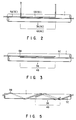
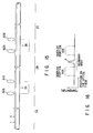
- Fig. 1 schematically shows an entire arrangement of an embodiment of the present invention
- Figs. 2 and 3 show a main part thereof.
- a fluid pipe 1 is a pipe of a pipeline for transporting, e.g., LNG, or a pipe of a piping for transporting and flowing various types of fluids, e.g., a high-temperature vapor and a heating medium, and is divided into a plurality of sections 2A, 2B, 2C, and 2D in the longitudinal direction.
- the sections 2A to 2D correspond to the respective maintenance sections of, e.g., a pipeline, and the respective rooms in a factory or building.
- boundaries (section boundaries) 3A, 3B, and 3C between the sections 2A to 2D correspond to the boundaries of adjacent maintenance sections or boundaries (walls) of adjacent rooms.
- a range having a predetermined length including the section boundary 3A together with two sides thereof, a range having a predetermined length including the section boundary 3B together with two sides thereof, and a range having a predetermined length including the two sections thereof, are defined as boundary areas 4A, 4B, and 4C.
- optical fibers 5A to 5D are respectively laid along the fluid pipe 1 in the sections 2A to 2D.
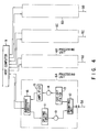
- the optical fibers 5A to 5D are respectively connected to distribution type temperature sensor processing units 6A to 6D, which are, in turn, connected to a host computer 9.
- the optical fibers 5A to 5D are laid for distances longer than the distances of the corresponding sections 2A to 2D, and are respectively laid at the portions, i.e., the end portions or the initial laying portions to be laid along the fluid pipe 1 along the boundary areas 4A to 4C.
- two optical fibers are respectively laid along the boundary areas 4A to 4C.
- both the optical fibers 5A and 5B or 5C and 5D to the fluid pipe 1 are superposed to be laid at the boundary area 4A or 4C along the fluid pipe 1 as shown in Fig. 1, and the ends of both the optical fibers 5B and 5C are superposed to be laid in the boundary area 4B as shown in Fig. 3.
- Arrangements of distribution type temperature sensor processing units 6A to 6D respectively connected to the optical fibers 5A to 5D may be the same as ordinary one, and are normally formed as shown in Fig. 4. More specifically, the processing units 6A to 6D emit laser pulse light as incident light to the optical fibers 5A to 5D, isolate Raman backscattering light to be returned from the optical fibers 5A to 5D, photodetect the Raman backscattering light, and amplify and average the same light. As shown in Fig.
- each processing unit comprises a laser light source 10 for oscillating laser pulse light as incident light to the optical fiber, a driving circuit 11 for driving the laser light source 10, a branching unit 12 for separating Raman scattering light from reflected scattering light to be returned from each of the optical fibers 5A to 5D, a cut-off filter 13 for cutting off the light component except the Raman light in the Raman scattering light, a photodetector 14 for converting the Raman scattering light to be output from the cut-off filter 13 into an electric signal, an amplifier 15 for amplifying the electric signal from the photodetector 14, and an averaging circuit 16 for improving the S/N ratio of the electric signal.
- the output signals from the respective processing units 6A to 6D are applied to the host computer 9, and a control signal from the host computer 9 is applied to each of the processing units 6.
- the host computer 9 calculates the electric signals from the processing units 6A to 6D to obtain a temperature distribution in the longitudinal direction of the optical fibers 5A to 5D and to further obtain the temperature peak position, i.e., the temperature increase peak position or the temperature drop peak position.
- the host computer 9 calculates the data obtained by the signals obtained from the portions of the two optical fibers and can accurately obtain the temperature peak position.
- the fluid pipe 1 is a pipe for transporting and flowing a low-temperature fluid, e.g., LNG.
- a low-temperature fluid e.g., LNG.
- the two optical fibers detect the temperature drop peak position. Therefore, which section the trouble occurrence location belongs to can be accurately determined by accurately detecting the temperature drop peak position, i.e., the trouble occurrence location.
- the sections 2A to 2D are sections (maintenance sections) determined for the purpose of maintenance, which maintenance section the trouble occurrence location belongs to can be accurately and quickly recognized, so that repair can be quickly and smoothly performed.
- the fluid pipe 1 is a pipe for flowing a high-temperature fluid, e.g., a high-temperature vapor or any other heating medium.
- a leakage trouble of the high-temperature fluid occurs due to cracking and the like of the pipe, the ambient temperature is increased at the trouble occurrence location and is detected by either one of the optical fibers 5A to 5D.
- the trouble occurrence location is especially in the vicinity of either one of the section boundaries 3A to 3C, in the boundary area including this section boundary, the two optical fibers detect the temperature increase peak position. Therefore, which section the trouble occurrence location belongs to can be accurately determined by accurately detecting the temperature increase peak position, i.e., the trouble occurrence location.
- sections 2A to 2D are determined to correspond to the rooms in a factory or building, in which room the trouble occurs can be accurately and quickly recognized, so that repair can be quickly and smoothly performed. Even when a trouble occurs within a wall as the boundary of wall members, this fact can be accurately detected.
- the concrete arrangement in which the optical fibers 5A to 5D are laid along the fluid pipe 1 is optional.
- the optical fibers may be supported by suitable supporting means (not shown) to be linearly laid along the longitudinal direction of the fluid pipe 1 or, as shown in Fig. 5, the optical fibers may be spirally wound on the fluid pipe 1.
- the fact that the portions of the two optical fibers are superposed to be laid along the boundary areas 4A to 4C is not limited to the case wherein the two optical fibers are superposed or arranged adjacently at the same side of the boundary areas 4A to 4C.
- it may include a case wherein the portions of the two optical fibers are arranged on the opposed surfaces of the fluid pipe 1 in the boundary areas 4A to 4C.
- the temperature abnormality detecting structure for the fluid pipe of the present invention when the occurrence location of a temperature abnormality caused by the leakage or outflow of the fluid from the pipe is to be detected by laying the optical fibers as the temperature detectors of a Raman scattering distribution type temperature sensor along the fluid pipe, the portions of the two detecting optical fibers of the two systems are superposed to be laid along the areas in the vicinity of the section boundary of the fluid pipe. Therefore, the temperature peak position, i.e., the occurrence location of a trouble such as leakage or outflow of the fluid is detected by the two separate optical fibers in the areas, hence the position can be accurately detected, and thus at which of the adjacent sections the trouble occurs can be easily determined.
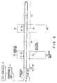
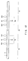
- Fig. 6 schematically shows an entire arrangement of a second embodiment of the present invention, and Fig. 2 shows a main part thereof.
- a fluid pipe 1 is a pipe of a pipeline for transporting, e.g., LNG, or a pipe of a piping for transporting and flowing various types of fluids, e.g., a high-temperature vapor and a heating medium, and is divided into a plurality of sections 2A, 2B, and 2C in the longitudinal direction.
- the sections 2A to 2C correspond to the respective maintenance sections of, e.g., a pipeline, and the respective rooms in a factory or building.
- boundaries (section boundaries) 3A and 3B between the sections 2A to 2C correspond to the boundaries of adjacent maintenance sections or boundaries (walls) of adjacent rooms.
- a range having a predetermined length including the section boundary 3A together with two sides thereof, and a range having a predetermined length including the section boundary 3B together with two sides thereof are defined as boundary areas 4A and 4B.
- An optical fiber 5 is laid along the fluid pipe 1 in the sections 2A to 2C.
- the optical fiber 5 is connected to a distribution type temperature sensor processing unit 6, which is, in turn, connected to a host computer 9.
- Two portions 51 and 52 disposed at a predetermined interval in the longitudinal direction of the optical fiber 5 are superposed to be laid along the fluid pipe 1.
- a surplus portion 53 is returned in a state isolated from the fluid pipe 1, and again laid at the portion 52 along the boundary area 4A of the fluid pipe 1.
- Two portions 54 and 55 disposed at a predetermined interval in the longitudinal direction of the optical fiber 5 are similarly superposed to be laid along the fluid pipe 1, and a surplus portion 56 similarly isolated from the fluid pipe 1 is formed between the portions 54 and 55 of the optical fiber 5.
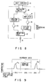
- An arrangement of distribution type temperature sensor processing unit 6 connected to the optical fiber 5 may be the same as ordinary one, and is normally formed as shown in Fig. 8. More specifically, the processing unit 6 emits laser pulse light as incident light to the optical fiber 5, isolates Raman backscattering light to be returned from the optical fiber 5, photodetects the Raman backscattering light, and amplifies and averages the same light. As shown in Fig.
- the processing unit 6 comprises a laser light source 10 for oscillating laser pulse light as incident light to the optical fiber 5, a driving circuit 11 for driving the laser light source 10, a branching unit 12 for separating Raman scattering light from reflected scattering light to be returned from the optical fiber 5, a cut-off filter 13 for cutting off the light component except the Raman light in the Raman scattering light, a photodetector 14 for converting the Raman scattering light to be output from the cut-off filter 13 into an electric signal, an amplifier 15 for amplifying the electric signal from the photodetector 14, and an averaging circuit 16 for improving the S/N ratio of the output signal from the amplifier 15.
- the output signal (the output signal from the averaging circuit 16) from the processing unit 6 is applied to the host computer 9, and a control signal from the host computer 9 is applied to the processing unit 6.
- the host computer 9 calculates the output signal from the processing unit 6 to obtain a temperature distribution in the longitudinal direction of the optical fiber 5 and to further obtain the temperature peak position, i.e., the temperature increase peak position or the temperature drop peak position.
- the host computer 9 calculates the data obtained by the signal from the portions of the optical fiber, and can accurately obtain the temperature peak position.
- a temperature peak occurs in the boundary area 4A, as shown in Fig. 9, temperature peaks P1 and P2 occur at the two portions 51 and 52 of the optical fiber 5. Accordingly, when the host computer 9 stores in advance the length of the surplus portion 53 and the superposing length of the portions 51 and 52, the host computer 9 can accurately obtain the temperature peak position of the boundary area 4A from the two peak positional data.
- the fluid pipe 1 is a pipe for transporting and flowing a low-temperature fluid, e.g., LNG.
- a low-temperature fluid e.g., LNG.
- the optical fiber 5 detects the temperature drop peak position. Therefore, which section the trouble occurrence location belongs to can be accurately determined by accurately detecting the temperature drop peak position, i.e., the trouble occurrence location. If the sections 2A to 2C are sections (maintenance sections) determined for the purpose of maintenance, which maintenance section the trouble occurrence location belongs to can be accurately and quickly recognized, so that repair can be quickly and smoothly performed.
- the fluid pipe 1 is a pipe for flowing a high-temperature fluid, e.g., a high-temperature vapor or any other heating medium.
- a leakage trouble of the high-temperature fluid occurs due to cracking and the like of the pipe, the ambient temperature is increased at the trouble occurrence location and is detected by the optical fiber 5.
- the trouble occurrence location is especially in the vicinity of either the section boundary 3A or 3B, in the boundary area including this section boundary, the two portions of the optical fiber 5 detect the temperature increase peak position. Therefore, which section the trouble occurrence location belongs to can be accurately determined by accurately detecting the temperature increase peak position, i.e., the trouble occurrence location.
- sections 2A to 2C are determined to correspond to the rooms in a factory or building, in which room the trouble occurs can be accurately and quickly recognized, so that repair can be quickly and smoothly performed. Even when a trouble occurs within a wall as the boundary of wall members, this fact can be accurately detected.
- a concrete arrangement in which the optical fiber 5 is laid along the fluid pipe 1 is optional.
- the optical fiber 5 may be supported by suitable supporting means (not shown) linearly along the longitudinal direction of the fluid pipe 1, or spirally wound on the fluid pipe 1 as shown in Fig. 10.
- suitable supporting means not shown
- the superposition of the two portions of the optical fiber 5 at the boundary areas 4A and 4B is not limited to a case wherein the optical fiber is superposed double at the same side of the boundary areas 4A and 4B or arranged adjacent to each other.
- the two portions 51, 52; 54, 55 of the optical fiber 5 are superposed to be laid along the boundary areas 4A and 4B.
- the present invention is not limited to the particular embodiment.
- three or more portions having different longitudinal directions of the optical fiber 5 may be superposed to be laid along the boundary areas 4A and 4B.
- three portions 51, 52, and 57 of the optical fiber 5 may be superposed to be laid along the boundary areas 4A and 4B.
- a surplus portion is not particularly formed between the portions 51, 52, and 57 of the optical fiber 5.
- the temperature abnormality detecting structure for the fluid pipe of the present invention when the occurrence location of a temperature abnormality caused by the leakage or outflow of the fluid from the pipe is to be detected by laying the optical fiber as the temperature detector of a Raman scattering distribution type temperature sensor along the fluid pipe, the two or more different portions of the same optical fiber having different longitudinal directions are superposed to be laid along the boundary areas of the fluid pipe. Therefore, the temperature peak position, i.e., the occurrence location of a trouble such as leakage or outflow of the fluid is detected by the two or more different portions of the optical fiber at the boundary area, hence the position can be accurately detected, and thus at which of the adjacent sections the trouble occurs can be easily determined.
- Fig. 12 schematically shows an entire arrangement of a third embodiment of the present invention.
- a fluid pipe 1 is a pipe of a pipeline for transporting, e.g., LNG, or a pipe of a piping for transporting and flowing various types of fluids, e.g., a high-temperature vapor and a heating medium, and is divided into a plurality of sections 2A, 2B, and 2C in the longitudinal direction.
- the sections 2A to 2C correspond to the respective maintenance sections of, e.g., a pipeline, and the respective rooms in a factory or building.
- boundaries (section boundaries) 3A and 3B between the sections 2A to 2C correspond to the boundaries of adjacent maintenance sections or boundaries (walls) of adjacent rooms.
- a range having a predetermined length including the section boundary 3A together with two sides thereof, and a range having a predetermined length including the section boundary 3B together with two sides thereof are defined as boundary areas 4A and 4B.
- An optical fiber 5 is laid along the entire length of the fluid pipe 1.
- the optical fiber 5 is connected to a distribution type temperature sensor processing unit 6, which is, in turn, connected to a host computer 9.
- the optical fiber 5 is wound at the portion of the longitudinal direction in a loop shape at the central portion of the boundary area 4B, i.e., the section boundary 3B so that the portion is formed as a surplus portion 61.
- the optical fiber 5 is similarly wound at the portion of the longitudinal direction in a loop shape at the central portion of the boundary area 4B, i.e., the section boundary 3B so that the portion is formed as a surplus portion 62.
- the surplus portions 61 and 62 wound in the loop shape are all isolated from the fluid pipe 1.
- An arrangement of the distribution type temperature sensor processing unit 6 connected to the optical fiber 5 may be the same as ordinary one, and is normally formed as shown in Fig. 13. More specifically, the processing unit 6 emits laser pulse light as incident light to the optical fiber 5, isolates Raman backscattering light to be returned from the optical fiber 5, photodetects the Raman backscattering light, and amplifies and averages the same light. As shown in Fig.
- the processing unit 6 comprises a laser light source 10 for oscillating laser pulse light as incident light to the optical fiber 5, a driving circuit 11 for driving the laser light source 10, a branching unit 12 for separating Raman scattering light to be returned from the optical fiber 5, a cut-off filter 13 for cutting off the light component except the Raman light in the Raman scattering light, a photodetector 14 for converting the raman scattering light to be output from the cut-off filter 13 into an electric signal, an amplifier 15 for amplifying the electric signal from the photodetector 14, and an averaging circuit 16 for improving the S/N ratio of the electric signal.
- the output signal (the output signal from the averaging circuit 16) is applied to the host computer 9, and a control signal from the host computer 9 is applied to the processing unit 6.
- the host computer 9 calculates the output signal from the processing unit 6 to obtain a temperature distribution in the longitudinal direction of the optical fiber 5 and to further obtain the temperature peak position, i.e., the temperature increase peak position or the temperature peak drop position.
- the host computer 9 stores in advance the data of the lengths of the surplus portions 61 and 62, calculates the data obtained by the signals from the optical fiber 5 to obtain the temperature change peak position, i.e., the occurrence location of the temperature abnormality, and can accurately detect which of the sides of the centers of the boundary areas 4A and 4B (section boundaries 3A and 3B) the position belongs to.
- a temperature peak occurs at the right side (the maintenance section 2B side) of the section boundary 3A at the center of the boundary area 4A, it can accurately detect that the temperature peak position P is located at the right side of the surplus portion 61 of the optical fiber 5.
- the fluid pipe 1 is a pipe for transporting and flowing a low-temperature fluid, e.g., LNG.
- a low-temperature fluid e.g., LNG.
- the optical fiber 5 When leakage or outflow of the low temperature fluid occurs due to cracking, damage, or destruction of the pipe, a decrease in ambient temperature caused by the leakage or outflow is detected by the optical fiber 5.
- the trouble occurrence location is especially in the vicinity of either the section boundary 3A or 3B, which section with respect to this section boundary the temperature drop peak position, i.e., the trouble occurrence location belongs to can be accurately determined.
- the sections 2A to 2C are sections (maintenance sections) determined for the purpose of maintenance, which maintenance section the trouble occurrence location belongs to can be accurately and quickly recognized, so that repair can be quickly and smoothly performed.
- the fluid pipe 1 is a pipe for flowing a high-temperature fluid, e.g., a high-temperature vapor or any other heating medium.
- a leakage trouble of the high-temperature fluid occurs due to cracking and the like of the pipe, the ambient temperature is increased at the trouble occurrence location and is detected by either portion of the optical fiber 5.
- the trouble occurrence location is especially in the vicinity of either the section boundary 3A or 3B, which section with respect to this section boundary the temperature increase peak position, i.e., the trouble occurrence location belongs to can be accurately determined. If the sections 2A to 2C are determined to correspond to the rooms in a factory or building, in which room the trouble occurs can be accurately and quickly recognized, so that repair can be quickly and smoothly performed.
- Fig. 15 shows a modification of the third embodiment of the present invention.
- loop-shaped marginal portions 61A, 61B; 61A, 61B are formed at the positions corresponding to both ends of boundary areas 4A and 4B at an optical fiber 5.
- a temperature peak occurs in the vicinities of the boundary areas 4A and 4B, it can be accurately determined at which of inside the boundary areas 4A and 4B and outside the boundary areas 4A and 4B the temperature peak position belongs to.
- Fig. 16 shows the relationship between the longitudinal position of the optical fiber when the temperature peak P occurs in the boundary area 4A and the detected temperature.
- Fig. 17 shows another modification as the combination of the embodiment in Fig. 12 and the modification of Fig. 15.
- loop-shaped surplus portions 61, 61A, 61B; 62, 62A, 62B are formed at three portions of both ends of boundary areas 4A and 4B and the center (section boundaries 3A and 3B) of an optical fiber 5.
- the temperature peak position belongs to according to the presence of the surplus portions 61 and 62, and it can also be easily and accurately determined at which of inside the boundary areas 4A and 4B the temperature peak position belongs to according to the presence of the surplus portions 61A, 61B; 62A, 62B at both ends of the boundary areas 4A and 4B at the same time.
- a concrete arrangement in which the optical fiber 5 is laid along the fluid pipe 1 is optional.
- the optical fiber 5 may be supported by suitable supporting means linearly along the longitudinal direction of the fluid pipe 1, or is spirally wound on the fluid pipe 1.
- the temperature abnormality detecting structure for the fluid pipe of the present invention when the occurrence location of a temperature abnormality caused by the leakage or outflow of the fluid from the pipe is to be detected by laying the optical fiber as the temperature detector of a Raman scattering distribution type temperature sensor along the fluid pipe, the surplus portion irrespective of the position of the fluid pipe in the longitudinal direction is formed at least at one portion of the fluid pipe in the vicinity of the boundary area. Therefore, the detecting accuracy of the temperature peak position, i.e., the occurrence location of a trouble such as the leakage or outflow of the fluid with respect to the surplus portion is high, and hence at which of the adjacent sections the trouble occurs can be easily determined.
Landscapes
- Physics & Mathematics (AREA)
- General Physics & Mathematics (AREA)
- Measuring Temperature Or Quantity Of Heat (AREA)
- Pipeline Systems (AREA)
- Examining Or Testing Airtightness (AREA)
Applications Claiming Priority (6)
| Application Number | Priority Date | Filing Date | Title |
|---|---|---|---|
| JP59803/92 | 1992-02-13 | ||
| JP4059803A JP2688792B2 (ja) | 1992-02-13 | 1992-02-13 | 流体流通管路における温度異常検出構造 |
| JP4059802A JP2631329B2 (ja) | 1992-02-13 | 1992-02-13 | 流体流通管路における温度異常検出構造 |
| JP59802/92 | 1992-02-13 | ||
| JP4059801A JP2631328B2 (ja) | 1992-02-13 | 1992-02-13 | 流体流通管路における温度異常検出構造 |
| JP59801/92 | 1992-02-13 |
Publications (3)
| Publication Number | Publication Date |
|---|---|
| EP0555846A2 true EP0555846A2 (fr) | 1993-08-18 |
| EP0555846A3 EP0555846A3 (en) | 1993-11-18 |
| EP0555846B1 EP0555846B1 (fr) | 1996-09-18 |
Family
ID=27297002
Family Applications (1)
| Application Number | Title | Priority Date | Filing Date |
|---|---|---|---|
| EP93102144A Expired - Lifetime EP0555846B1 (fr) | 1992-02-13 | 1993-02-11 | Canalisations de fluide avec structure de détection de lieu d'anormalie de température |
Country Status (6)
| Country | Link |
|---|---|
| US (1) | US5308162A (fr) |
| EP (1) | EP0555846B1 (fr) |
| KR (1) | KR960013996B1 (fr) |
| AU (1) | AU643914B2 (fr) |
| CA (1) | CA2089223C (fr) |
| DE (1) | DE69304728T2 (fr) |
Cited By (8)
| Publication number | Priority date | Publication date | Assignee | Title |
|---|---|---|---|---|
| WO1996024826A1 (fr) * | 1995-02-09 | 1996-08-15 | GESO Gesellschaft für Sensorik, Geotechnischen Umweltschutz und Mathematische Modellierung mbH Jena | Procede de controle et de surveillance de l'etat de digues, de barrages fixes ou mobiles, ou de constructions analogues |
| DE19509129A1 (de) * | 1995-02-24 | 1996-08-29 | Geso Ges Fuer Sensorik Geotech | Verfahren und Vorrichtung zur Kontrolle und Überwachung des Zustandes von Rohren, Behältern, Pipelines oder dergleichen |
| WO1996026425A1 (fr) * | 1995-02-24 | 1996-08-29 | Geso, Gesellschaft Für Sensorik, Geotechnischen Umweltschutz Und Mathematische Modellierung Mbh, Jena | Procede et dispositif pour controler et surveiller l'etat de tuyaux, de conteneurs, de pipelines ou analogues |
| WO2004031738A1 (fr) * | 2002-10-01 | 2004-04-15 | Lattice Intellectual Property Ltd | Detecteur de la corrosion des fibres optiques |
| WO2004017037A3 (fr) * | 2002-08-16 | 2005-01-06 | Sensor Highway Ltd | Systeme et procede permettant de detecter une fuite de fluide dans un tuyau |
| EP2037246A3 (fr) * | 2007-09-07 | 2011-05-18 | Ulrich Glombitza | Procédé destiné à la surveillance de l'état d'un tuyau pour un habillage dans un système de tuyaux ou de canaux |
| CN105805556A (zh) * | 2015-09-30 | 2016-07-27 | 李儒峰 | 一种分布式光纤泄漏监测系统 |
| CN109595470A (zh) * | 2019-01-15 | 2019-04-09 | 广东聚源管业实业有限公司 | 一种分布式管道检测方法及系统 |
Families Citing this family (32)
| Publication number | Priority date | Publication date | Assignee | Title |
|---|---|---|---|---|
| US5356220A (en) * | 1992-05-29 | 1994-10-18 | Kawasaki Steel Corporation | Method and apparatus for monitoring temperature of blast furnace and temperature control system using temperature monitoring apparatus |
| US5839830A (en) * | 1994-09-19 | 1998-11-24 | Martin Marietta Energy Systems, Inc. | Passivated diamond film temperature sensing probe and measuring system employing same |
| WO2003021193A2 (fr) * | 2001-08-29 | 2003-03-13 | Conagra Grocery Products Company | Dispositif et procede pour l'elimination de l'accumulation de matiere sur des jauges |
| US6715914B1 (en) * | 2002-06-26 | 2004-04-06 | The United States Of America As Represented By The Administrator Of The National Aeronautics And Space Administration | Apparatus and method for thermal performance testing of pipelines and piping systems |
| US20040086020A1 (en) * | 2002-10-28 | 2004-05-06 | Jordahl Marlow C. | Method and device for detecting altered physical and chemical properties in a liquid environment |
| JP5223681B2 (ja) * | 2006-12-28 | 2013-06-26 | 住友電気工業株式会社 | 流動体の物理量測定方法及び制御方法 |
| US8360635B2 (en) * | 2007-01-09 | 2013-01-29 | Schlumberger Technology Corporation | System and method for using one or more thermal sensor probes for flow analysis, flow assurance and pipe condition monitoring of a pipeline for flowing hydrocarbons |
| JP5227635B2 (ja) * | 2008-03-28 | 2013-07-03 | 古河電気工業株式会社 | 流体漏洩検知システム |
| JP5184177B2 (ja) * | 2008-03-28 | 2013-04-17 | 古河電気工業株式会社 | 極低温流体輸送用可撓管 |
| WO2010118342A1 (fr) * | 2009-04-09 | 2010-10-14 | Schlumberger Technology Corporation | Procédé et système pour la détection d'une invasion de fluide dans un espace annulaire d'un tuyau flexible |
| JP5218648B2 (ja) * | 2009-05-01 | 2013-06-26 | 富士通株式会社 | 温度測定システム及び温度測定方法 |
| US8410946B2 (en) * | 2010-03-05 | 2013-04-02 | General Electric Company | Thermal measurement system and method for leak detection |
| US8702372B2 (en) | 2010-05-03 | 2014-04-22 | Bha Altair, Llc | System and method for adjusting compressor inlet fluid temperature |
| US9019108B2 (en) | 2010-08-05 | 2015-04-28 | General Electric Company | Thermal measurement system for fault detection within a power generation system |
| US9097182B2 (en) | 2010-08-05 | 2015-08-04 | General Electric Company | Thermal control system for fault detection and mitigation within a power generation system |
| CN102997049A (zh) * | 2011-09-14 | 2013-03-27 | 中国石油天然气集团公司 | 天然气管道泄漏光纤监测系统的光纤传感器安装方法 |
| CN102997052A (zh) * | 2011-09-14 | 2013-03-27 | 中国石油天然气集团公司 | 天然气管道泄漏检测的光纤传感器 |
| US9157878B2 (en) * | 2011-10-13 | 2015-10-13 | Thermal Wave Imaging, Inc. | System and method for detecting aberrations in a conduit |
| US9574949B2 (en) | 2012-02-17 | 2017-02-21 | Roctest Ltd | Automated system and method for testing the efficacy and reliability of distributed temperature sensing systems |
| CN104755892B (zh) * | 2012-10-26 | 2017-03-08 | 富士通株式会社 | 温度测定系统以及异常检测方法 |
| CN103728539B (zh) * | 2014-01-23 | 2016-06-22 | 华北电力大学(保定) | 基于分布式光纤测温的电缆电气故障仿真分析方法 |
| US9581490B2 (en) | 2014-04-17 | 2017-02-28 | Saudi Arabian Oil Company | Pipeline integrity monitoring using fiber optics |
| CA2986127C (fr) | 2015-06-18 | 2020-12-08 | Pure Technologies Ltd. | Detection d'exposition de pipelines dans les franchissements de nappes et de cours d'eau |
| EP3150981A1 (fr) * | 2015-10-01 | 2017-04-05 | Linde Aktiengesellschaft | Mesure de la temperature de surface a l'aide de conducteur lumineux destinee a surveiller des systemes de sortie de reformeur |
| US10656041B2 (en) * | 2015-11-24 | 2020-05-19 | Schlumberger Technology Corporation | Detection of leaks from a pipeline using a distributed temperature sensor |
| JP6613934B2 (ja) * | 2016-02-05 | 2019-12-04 | 住友電気工業株式会社 | パイプタイプ固体絶縁ケーブルシステム、パイプタイプ固体絶縁ケーブルシステムの構築方法、及びパイプタイプ固体絶縁ケーブルシステムの冷却方法 |
| US20180249758A1 (en) * | 2017-03-05 | 2018-09-06 | SMB Labs, LLC | Dynamically Responsive Smoking Apparatus and Method of Affixing Electronics Thereon |
| CN110906171B (zh) * | 2019-10-29 | 2021-08-10 | 中国石油化工股份有限公司 | 基于动态包络线法的管道保温状况监测和分级控制方法 |
| CN111120877B (zh) * | 2019-12-12 | 2020-11-27 | 同济大学 | 一种基于分布式光纤测温的排水管网泄漏监测设备 |
| SE544356C2 (en) * | 2020-01-15 | 2022-04-19 | Saab Ab | Arrangement and method for obtaining a quantity related to a temperature along a part of an optical fibre |
| CN113738960B (zh) * | 2021-08-11 | 2023-04-11 | 临海伟星新型建材有限公司 | 一种可显示管道堵塞位置的智能输送管道 |
| CN116717735A (zh) * | 2023-06-02 | 2023-09-08 | 三峡智慧水务科技有限公司 | 一种基于温度的多点式管网地下水入渗监测装置及方法 |
Family Cites Families (15)
| Publication number | Priority date | Publication date | Assignee | Title |
|---|---|---|---|---|
| US4270049A (en) * | 1978-06-12 | 1981-05-26 | Ishikawajima-Harima Jukogyo Kabushiki Kaisha | Liquid leakage detection system |
| US4240747A (en) * | 1979-10-03 | 1980-12-23 | Battelle Memorial Institute | Refractive-index responsive light-signal system |
| JPS56157833A (en) * | 1980-05-08 | 1981-12-05 | Ishikawajima Harima Heavy Ind Co Ltd | Detecting method of leakage of low-temperature fluid |
| JPS5746138A (en) * | 1980-09-05 | 1982-03-16 | Fujitsu Ltd | Low-temperature gas sensor |
| US4362057A (en) * | 1980-10-10 | 1982-12-07 | Electric Power Research Institute, Inc. | Optical fiber temperature sensor |
| US4812645A (en) * | 1981-08-24 | 1989-03-14 | G2 Systems Corporation | Structural monitoring system using fiber optics |
| GB2170593B (en) * | 1985-02-01 | 1988-09-14 | Central Electr Generat Board | Temperature measurement |
| JPH0743286B2 (ja) * | 1988-04-19 | 1995-05-15 | 日立電線株式会社 | 光ファイバ式分布形温度センサ |
| JPH0769223B2 (ja) * | 1989-06-08 | 1995-07-26 | 旭硝子株式会社 | 温度測定方法および分布型光ファイバー温度センサー |
| JPH03180731A (ja) * | 1989-12-11 | 1991-08-06 | Nkk Corp | 熱媒輸送用配管の熱媒漏洩検知方法 |
| US5067810A (en) * | 1990-06-21 | 1991-11-26 | Reliance Comm/Tec Corporation | Shared laser tandem optical time domain reflectometer |
| US5178465A (en) * | 1990-07-11 | 1993-01-12 | Fujikura Ltd. | Optical fiber laying structure for electric power cable line trouble occurrence location detecting system |
| JPH071296B2 (ja) * | 1990-07-20 | 1995-01-11 | 株式会社フジクラ | 電力ケーブル線路事故点検出システムにおける検出用光ファイバ布設構造 |
| JP2581607B2 (ja) * | 1990-07-11 | 1997-02-12 | 株式会社フジクラ | 電力ケーブル線路事故点検出システムにおける検出用光ファイバ布設構造 |
| JPH0748073B2 (ja) * | 1990-07-13 | 1995-05-24 | 株式会社フジクラ | 電力ケーブル線路事故点検出システムにおける検出用光ファイバ布設構造 |
-
1993
- 1993-02-10 CA CA002089223A patent/CA2089223C/fr not_active Expired - Fee Related
- 1993-02-10 US US08/015,996 patent/US5308162A/en not_active Expired - Lifetime
- 1993-02-11 DE DE69304728T patent/DE69304728T2/de not_active Expired - Fee Related
- 1993-02-11 EP EP93102144A patent/EP0555846B1/fr not_active Expired - Lifetime
- 1993-02-12 AU AU32999/93A patent/AU643914B2/en not_active Ceased
- 1993-02-13 KR KR1019930002028A patent/KR960013996B1/ko not_active Expired - Fee Related
Cited By (12)
| Publication number | Priority date | Publication date | Assignee | Title |
|---|---|---|---|---|
| WO1996024826A1 (fr) * | 1995-02-09 | 1996-08-15 | GESO Gesellschaft für Sensorik, Geotechnischen Umweltschutz und Mathematische Modellierung mbH Jena | Procede de controle et de surveillance de l'etat de digues, de barrages fixes ou mobiles, ou de constructions analogues |
| DE19509129A1 (de) * | 1995-02-24 | 1996-08-29 | Geso Ges Fuer Sensorik Geotech | Verfahren und Vorrichtung zur Kontrolle und Überwachung des Zustandes von Rohren, Behältern, Pipelines oder dergleichen |
| WO1996026425A1 (fr) * | 1995-02-24 | 1996-08-29 | Geso, Gesellschaft Für Sensorik, Geotechnischen Umweltschutz Und Mathematische Modellierung Mbh, Jena | Procede et dispositif pour controler et surveiller l'etat de tuyaux, de conteneurs, de pipelines ou analogues |
| DE19509129C2 (de) * | 1995-02-24 | 1998-07-02 | Geso Ges Fuer Sensorik Geotech | Verfahren und Vorrichtung zur Kontrolle und Überwachung des Zustandes von Rohren, Behältern, Pipelines oder dergleichen |
| WO2004017037A3 (fr) * | 2002-08-16 | 2005-01-06 | Sensor Highway Ltd | Systeme et procede permettant de detecter une fuite de fluide dans un tuyau |
| WO2004031738A1 (fr) * | 2002-10-01 | 2004-04-15 | Lattice Intellectual Property Ltd | Detecteur de la corrosion des fibres optiques |
| EP2037246A3 (fr) * | 2007-09-07 | 2011-05-18 | Ulrich Glombitza | Procédé destiné à la surveillance de l'état d'un tuyau pour un habillage dans un système de tuyaux ou de canaux |
| US8162535B2 (en) | 2007-09-07 | 2012-04-24 | Ulrich Glombitza | Method for monitoring the state of a tube for a coating in a system of pipes or ducts |
| US8727614B2 (en) | 2007-09-07 | 2014-05-20 | Ulrich Glombitza | Method for monitoring the state of a tube for a coating in a system of pipes or ducts |
| CN105805556A (zh) * | 2015-09-30 | 2016-07-27 | 李儒峰 | 一种分布式光纤泄漏监测系统 |
| CN105805556B (zh) * | 2015-09-30 | 2018-02-27 | 李儒峰 | 一种分布式光纤泄漏监测系统 |
| CN109595470A (zh) * | 2019-01-15 | 2019-04-09 | 广东聚源管业实业有限公司 | 一种分布式管道检测方法及系统 |
Also Published As
| Publication number | Publication date |
|---|---|
| EP0555846A3 (en) | 1993-11-18 |
| DE69304728D1 (de) | 1996-10-24 |
| KR930018265A (ko) | 1993-09-21 |
| CA2089223A1 (fr) | 1993-08-14 |
| KR960013996B1 (ko) | 1996-10-11 |
| AU643914B2 (en) | 1993-11-25 |
| EP0555846B1 (fr) | 1996-09-18 |
| CA2089223C (fr) | 1999-06-01 |
| US5308162A (en) | 1994-05-03 |
| AU3299993A (en) | 1993-09-02 |
| DE69304728T2 (de) | 1997-03-06 |
Similar Documents
| Publication | Publication Date | Title |
|---|---|---|
| EP0555846B1 (fr) | Canalisations de fluide avec structure de détection de lieu d'anormalie de température | |
| EP0466155B1 (fr) | Construction de câbles optiques à installer au système de détection d'anomalies dans une ligne d'alimentation électrique | |
| KR101462445B1 (ko) | 광 온도센서 측정 시스템 및 그 방법 | |
| WO2012145829A1 (fr) | Procédé et appareil de détection de la vitesse d'un flux gazeux à haute température | |
| WO2002012828A2 (fr) | Dispositif generant un rideau de lumiere | |
| EP2746741B1 (fr) | Dispositif et procédé de mesure de distribution de température | |
| JP4151530B2 (ja) | 地下空間の防災システム | |
| JP2631328B2 (ja) | 流体流通管路における温度異常検出構造 | |
| JPH0836681A (ja) | 光ファイバを用いた火災検知設備 | |
| US5739526A (en) | Fibre-optic photoelectric beam device having a transmitting optical unit for detecting a moving object through a control district | |
| CN101324446A (zh) | 一种扰动传感定位方法 | |
| JP2688792B2 (ja) | 流体流通管路における温度異常検出構造 | |
| KR101520840B1 (ko) | 광케이블을 이용한 온도 측정 시스템 | |
| JP2631329B2 (ja) | 流体流通管路における温度異常検出構造 | |
| JP2962452B2 (ja) | 低温設備の異常検出方法 | |
| JP5099475B2 (ja) | 大電力ミリ波伝送系の異常診断装置 | |
| JPH0472582A (ja) | 電力ケーブル線路事故点検出システムにおける検出用光ファイバ布設構造 | |
| JPH0470527A (ja) | 電力ケーブル線路事故点検出システムにおける検出用光ファイバ布設構造 | |
| KR20010039425A (ko) | 보일러 열팽창 감시장치 | |
| CN119572967B (zh) | 一种高能管道泄漏监测装置 | |
| JPS6014196Y2 (ja) | 異常温度検知装置 | |
| CN108507737A (zh) | 天然气站场泄漏监测装置 | |
| JPS6116922B2 (fr) | ||
| JP2005083875A (ja) | トンネル内の特定ガス濃度測定装置およびトンネル内の排気方法 | |
| JPS60146112A (ja) | 光反射型検出装置 |
Legal Events
| Date | Code | Title | Description |
|---|---|---|---|
| PUAI | Public reference made under article 153(3) epc to a published international application that has entered the european phase |
Free format text: ORIGINAL CODE: 0009012 |
|
| 17P | Request for examination filed |
Effective date: 19930211 |
|
| AK | Designated contracting states |
Kind code of ref document: A2 Designated state(s): DE FR GB IT |
|
| PUAL | Search report despatched |
Free format text: ORIGINAL CODE: 0009013 |
|
| AK | Designated contracting states |
Kind code of ref document: A3 Designated state(s): DE FR GB IT |
|
| 17Q | First examination report despatched |
Effective date: 19950404 |
|
| GRAH | Despatch of communication of intention to grant a patent |
Free format text: ORIGINAL CODE: EPIDOS IGRA |
|
| GRAA | (expected) grant |
Free format text: ORIGINAL CODE: 0009210 |
|
| GRAH | Despatch of communication of intention to grant a patent |
Free format text: ORIGINAL CODE: EPIDOS IGRA |
|
| AK | Designated contracting states |
Kind code of ref document: B1 Designated state(s): DE FR GB IT |
|
| ITF | It: translation for a ep patent filed | ||
| REF | Corresponds to: |
Ref document number: 69304728 Country of ref document: DE Date of ref document: 19961024 |
|
| ET | Fr: translation filed | ||
| PLBE | No opposition filed within time limit |
Free format text: ORIGINAL CODE: 0009261 |
|
| STAA | Information on the status of an ep patent application or granted ep patent |
Free format text: STATUS: NO OPPOSITION FILED WITHIN TIME LIMIT |
|
| 26N | No opposition filed | ||
| PGFP | Annual fee paid to national office [announced via postgrant information from national office to epo] |
Ref country code: FR Payment date: 19980109 Year of fee payment: 6 |
|
| PGFP | Annual fee paid to national office [announced via postgrant information from national office to epo] |
Ref country code: GB Payment date: 19980202 Year of fee payment: 6 |
|
| PGFP | Annual fee paid to national office [announced via postgrant information from national office to epo] |
Ref country code: DE Payment date: 19980324 Year of fee payment: 6 |
|
| PG25 | Lapsed in a contracting state [announced via postgrant information from national office to epo] |
Ref country code: GB Free format text: LAPSE BECAUSE OF NON-PAYMENT OF DUE FEES Effective date: 19990211 |
|
| GBPC | Gb: european patent ceased through non-payment of renewal fee |
Effective date: 19990211 |
|
| PG25 | Lapsed in a contracting state [announced via postgrant information from national office to epo] |
Ref country code: FR Free format text: LAPSE BECAUSE OF NON-PAYMENT OF DUE FEES Effective date: 19991029 |
|
| PG25 | Lapsed in a contracting state [announced via postgrant information from national office to epo] |
Ref country code: DE Free format text: LAPSE BECAUSE OF NON-PAYMENT OF DUE FEES Effective date: 19991201 |
|
| REG | Reference to a national code |
Ref country code: FR Ref legal event code: ST |
|
| PG25 | Lapsed in a contracting state [announced via postgrant information from national office to epo] |
Ref country code: IT Free format text: LAPSE BECAUSE OF NON-PAYMENT OF DUE FEES;WARNING: LAPSES OF ITALIAN PATENTS WITH EFFECTIVE DATE BEFORE 2007 MAY HAVE OCCURRED AT ANY TIME BEFORE 2007. THE CORRECT EFFECTIVE DATE MAY BE DIFFERENT FROM THE ONE RECORDED. Effective date: 20050211 |