EP0555860B1 - Système de contrôle de la stabilité de la direction d'un véhicule - Google Patents
Système de contrôle de la stabilité de la direction d'un véhicule Download PDFInfo
- Publication number
- EP0555860B1 EP0555860B1 EP93102176A EP93102176A EP0555860B1 EP 0555860 B1 EP0555860 B1 EP 0555860B1 EP 93102176 A EP93102176 A EP 93102176A EP 93102176 A EP93102176 A EP 93102176A EP 0555860 B1 EP0555860 B1 EP 0555860B1
- Authority
- EP
- European Patent Office
- Prior art keywords
- vehicle
- steering
- yaw rate
- counter
- oversteering
- Prior art date
- Legal status (The legal status is an assumption and is not a legal conclusion. Google has not performed a legal analysis and makes no representation as to the accuracy of the status listed.)
- Expired - Lifetime
Links
- 230000001133 acceleration Effects 0.000 claims description 11
- 238000010586 diagram Methods 0.000 description 4
- 238000000034 method Methods 0.000 description 3
- 238000010420 art technique Methods 0.000 description 1
- 238000010276 construction Methods 0.000 description 1
- 238000012986 modification Methods 0.000 description 1
- 230000004048 modification Effects 0.000 description 1
Images


Classifications
-
- B—PERFORMING OPERATIONS; TRANSPORTING
- B60—VEHICLES IN GENERAL
- B60K—ARRANGEMENT OR MOUNTING OF PROPULSION UNITS OR OF TRANSMISSIONS IN VEHICLES; ARRANGEMENT OR MOUNTING OF PLURAL DIVERSE PRIME-MOVERS IN VEHICLES; AUXILIARY DRIVES FOR VEHICLES; INSTRUMENTATION OR DASHBOARDS FOR VEHICLES; ARRANGEMENTS IN CONNECTION WITH COOLING, AIR INTAKE, GAS EXHAUST OR FUEL SUPPLY OF PROPULSION UNITS IN VEHICLES
- B60K28/00—Safety devices for propulsion-unit control, specially adapted for, or arranged in, vehicles, e.g. preventing fuel supply or ignition in the event of potentially dangerous conditions
- B60K28/10—Safety devices for propulsion-unit control, specially adapted for, or arranged in, vehicles, e.g. preventing fuel supply or ignition in the event of potentially dangerous conditions responsive to conditions relating to the vehicle
Definitions
- the present invention relates to a steering stability control system for a vehicle, comprising a turning state judging means for judging the turning state of the vehicle to deliver an oversteering signal or an understeering signal, and a steering stability control means for controlling the output torque from an engine on the basis of the output from the turning state judging means.
- EP-A-0 282 041 describes a steering stability control system for a vehicle according to the preamble of claim 1, which is designed such that a reference yaw rate to be intrinsically generated by the vehicle in accordance with the operational condition of the vehicle is compared with an actual yaw rate actually generated; the turning state of the vehicle is judged, i.e., it is judged whether the vehicle is in an oversteering or in an understeering, and the output torque from the engine is increased or reduced in accordance with the judged turning state, thereby compensating for the oversteering and the understeering to properly maintain the steering stability of the vehicle.
- Fig. 5 illustrates the variations in steering angle ⁇ of a steering wheel, reference yaw rate Y REF and actual yaw rate Y.
- the driver counter-steers the steering wheel in a counterclockwise direction (which is referred to as a negative direction herein) from a position indicated by (3) for the purpose of maintaining the turning radius constant.
- This causes the steering angle ⁇ to become 0 (zero) at a position indicated by (4) and further to become the negative maximum value at a position indicated by (5).
- the steering angle ⁇ becomes 0 (zero) again.
- the reference yaw rate Y REF determined on the steering angle ⁇ follows the variation in steering angle ⁇ with a slight delay due to an influence of a play of a steering system or the like.
- the actual yaw rate Y which is an actual yaw rate of the vehicle does not immediately follow the counter-steering operation due to an inertia of the vehicle and is maintained positive with the exception of the last stage of the turning.
- Table 1 illustrates the criterion for prior art judgement of an oversteering and an understeering of the vehicle.
- the positive and negative of the reference yaw rate Y REF (the axis of ordinates) are compared with the positive and negative of a deviation Y-Y REF (the axis of abscissas) resulting from subtraction of the reference yaw rate Y REF from the actual yaw rate Y, and the oversteering and the understeering can be judged by a combination of these positives and negatives.
- the region (B) corresponds to a left and upper column, and in the region (B), it is judged that the vehicle is in the oversteering.
- the reference yaw rate Y REF is negative and the deviation Y-Y REF resulting from subtraction of the reference yaw rate Y REF from the actual yaw rate Y is non-negative. Therefore, the region (C) corresponds to a left and lower column, and in the region (B), it is judged that the vehicle is in the understeering.
- the output torque from the engine in the front wheel drive vehicle can be increased or reduced, thereby avoiding the turning of the vehicle in an undesirable direction.
- a steering stability control system for a vehicle, comprising a turning state judging means for judging a turning state of the vehicle to output an oversteering signal or an understeering signal, and a steering stability control means for controlling an output torque from an engine on the basis of an output from the turning state judging means, wherein said system further includes a counter-steering state judging means capable of judging the counter-steering state of the vehicle and outputting an oversteering signal to the turning state judging means, when the counter-steering state is judged.
- the accident or inadvertent delivery of an understeering signal by the turning state judging means can be prevented, and an intrinsic oversteering signal can be delivered. Therefore, it is possible to correctly operate the steering stability control means to previously avoid a disadvantage that the vehicle is turned in an undesirable direction.
- the turning state judging means judges the turning state on the basis of a deviation of an actual yaw rate of the vehicle from a reference yaw rate of the vehicle.
- the turning state judging means can reliably judge the oversteering state and the understeering state of the vehicle.
- the counter-steering state judging means judges a counter-steering state on the basis of a steering angle and a lateral acceleration of the vehicle.
- the counter-steering state judging means can reliably judge the counter-steering state of the vehicle.
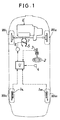
- a vehicle to which the present invention is applied is a front wheel drive vehicle and comprises a pair of left and right driven wheels W FL and W FR driven by an engine E, and a pair of left and right follower wheels W RL and W RR .
- a pair of left and right follower wheel speed detecting means 1 RL and 1 RR are provided on the follower wheels W RL and W RR for detecting follower wheel speeds V RL and V RR , respectively.
- a steering angle detecting means 3 is provided on a steering wheel detector 3 for detecting a steering angle ⁇ , and a lateral acceleration detecting means 4 is mounted in place on a vehicle body for detecting a lateral acceleration G.
- a throttle valve 7 is mounted in an intake passage 5 of the engine E and connected to and opened and closed by a pulse motor 6.
- the follower wheel speed detecting means 1 RL and 1 RR , the steering angle detecting means 3, the lateral acceleration detecting means 4 and the pulse motor 6 are connected to an electronic control unit U comprising a microcomputer.
- Fig. 2 illustrates the electronic control unit U for controlling the output torque from the engine E by calculating signals from the various detecting means according to a controlling program and driving the throttle valve 7 by the pulse motor 6, so as to maintain the steering stability during turning of the vehicle.
- the electronic control unit U is comprised of a central processing unit (CPU) 11 for performing such calculation; a read only memory (ROM) 12 having the controlling program and various data such as tables stored therein; a random access memory (RAM) 13 for temporarily storing the output signals from the detecting means and the calculation results; an input section 14 to which the various detecting means, i.e., the follower wheel speed detecting means 1 RL and 1 RR , the steering angle detecting means 3 and the lateral acceleration detecting means 4 are connected; and an output section 15 to which the pulse motor 6 is connected.
- CPU central processing unit
- ROM read only memory
- RAM random access memory
- the electronic control unit U calculates the various signals inputted thereinto through the input section 14, the data stored in the real only memory 12 and the like in the central processing unit 11 on the basis of the controlling program which will be described hereinafter, and finally drives the pulse motor 6 through the output section 15.
- This causes the throttle valve 7 to be controlled to vary the output torque from the engine E and as a result, the torque of the driven wheels is controlled to an optimal value to prevent the vehicle from being turned in an undesirable direction.
- the left and right follower wheel speeds V RL and V RR detected by the left and right follower wheel speed detecting means 1 and 1 are inputted into an actual yaw rate calculating means 21, where an actual yaw rate Y of the vehicle is determined by multiplying a difference (V RL - V RR ) between the follower wheel speeds V RL and V RR by a predetermined constant corresponding to a tread of each of the left and right follower wheels W RL and W RR .
- the left and right follower wheel speeds V RL and V RR are inputted into a vehicle speed calculating means 22, where a vehicle speed V V of the vehicle is determined by calculating an average (V RL + V RR )/2 of the follower wheel speeds V RL and V RR .
- the vehicle speed V V and a steering angle ⁇ detected by the steering angle detecting means 3 are inputted into a reference yaw rate calculating means 23, where a reference yaw rate Y REF is determined.
- the reference yaw rate Y REF is a reference value as a standard of a yaw rate to be generated when a driver of the vehicle has steered the steering wheel 2 through a steering angle ⁇ at the current vehicle speed V V , and is used as a criterion in judging the turning state of the vehicle, i.e., an oversteering and an understeering.
- the actual yaw rate Y and the reference yaw rate Y REF are inputted into a turning state judging means 24, where it is judged whether the vehicle is in an oversteering state or an understeering state. If a value during clockwise turning of the vehicle is positive, the turning state judging means 24 compares the positive and negative of the actual yaw rate Y with the positive and negative of a deviation Y-Y REF resulting from subtraction of the reference yaw rate Y REF from the actual yaw rate Y, and judges the oversteering and the understeering by a combination of these positives and negatives, as shown in Table 2, and also judges the degree of each of the oversteering and the understeering by an absolute value of the deviation Y-Y REF . As apparent from comparison of Tables 1 and 2, Tables 1 and 2 are different from each other in that the reference yaw rate Y REF in the axis of ordinates in Table 1 is replaced by the actual ya
- a region (A') and a region (C') are understeering regions, and a region (B') is an oversteering region. If this is compared with the turning state in the prior art shown in Fig. 5, the region (C') misjudged as being the understeering region is reduced as compared with a region (C) in the prior art, leading to an improved judging accuracy. However, the misjudgment may be still performed in the region (C') even by the above-described technique and hence, according to the present invention, the following judgement is further carried out in a counter-steering state judging means 26.
- the positive and negative of the lateral acceleration G detected by the lateral acceleration detecting means 4 is compared with the positive and negative of the steering angle ⁇ detected by the steering angle detecting means 3, thereby judging whether the vehicle is in a state of normal-steering or in a state of counter-steering. If it has been decided that the vehicle is in the counter-steering state, the vehicle is considered to be in the oversteering, irrespective of the result of judgement in Table 2.
- the lateral acceleration G converted into the steering angle ⁇ is positive, and the steering angle ⁇ is positive, and hence, the region (D) is a normal-steering region in correspondence to a left and upper column in Table 3.
- the lateral acceleration G is positive and the steering angle ⁇ is negative, and hence, the region (E) is a counter-steering region in correspondence to a right and upper column in Table 3.
- the region (E) decided as being the counter-steering region the vehicle is considered to be in the oversteering state, irrespective of the result of judgement in Table 2. Therefore, the region (C') in which it should be intrinsically misjudged that the vehicle is in the understeering can correctly be judged as being a region in which the vehicle is in the oversteering.
- the turning state judging means 24 delivers an oversteering signal or an understeering signal on the basis of the outputs from the actual yaw rate calculating means 21 and the reference yaw rate calculating means 23, i.e., on the basis of Table 2.
- the turning state judging means 24 delivers the oversteering signal irrespective of the outputs from the actual yaw rate calculating means 21 and the reference yaw rate calculating means 23.
- the oversteering signal When the oversteering signal is inputted from the turning state judging means 24 into a steering stability control means 25, the latter opens the throttle valve 7 through the pulse motor 6 to increase the output torque from the engine E. If the output torque from the engine E in the front wheel drive vehicle is increased, the oversteering is corrected toward the understeering, because the vehicle has an understeering tendency, thereby preventing the vehicle from being turned in an undesirable direction. Inversely, if the vehicle is in the understeering and the understeering signal is supplied from the turning state judging means 24 into the steering stability control means 25, the latter closes the throttle valve 7 through the pulse motor 6 to reduce the output torque from the engine E. If the output torque from the engine E in the front wheel drive vehicle is reduced, the understeering is corrected toward the oversteering, because the vehicle has an oversteering tendency, thereby preventing the vehicle from being turned in an undesirable direction.
- the present invention is also applicable to a rear wheel drive vehicle having front wheels as follower wheels and rear wheels as driven wheels.
- the output torque from the engine is controlled to be reduced, in contrast with in the above-described embodiment.
Landscapes
- Engineering & Computer Science (AREA)
- Chemical & Material Sciences (AREA)
- Combustion & Propulsion (AREA)
- Transportation (AREA)
- Mechanical Engineering (AREA)
- Control Of Vehicle Engines Or Engines For Specific Uses (AREA)
- Steering Control In Accordance With Driving Conditions (AREA)
- Electrical Control Of Air Or Fuel Supplied To Internal-Combustion Engine (AREA)
Claims (3)
- Système de contrôle de la stabilité de la direction d'un véhicule ayant un moteur (E), comprenant un moyen d'appréciation d'état de prise de virage (24) pour apprécier un état de prise de virage du véhicule (1) se trouvant dans un état de survirage ou de sousvirage et pour produire respectivement un signal de survirage ou un signal de sousvirage, et un moyen de contrôle de stabilité de direction (25) pour commander le couple de sortie dudit moteur (E) sur la base d'un signal de sortie émis par ledit moyen d'appréciation d'état de prise de virage (24), caractérisé en ce que
ledit système comprend en outre un moyen d'appréciation d'état de contre-braquage (26) capable d'apprécier un état de contre-braquage du véhicule et d'envoyer un signal de survirage audit moyen d'appréciation d'état de virage (24) lorsque ledit état de contre-braquage est apprécié. - Système de contrôle de stabilité de la direction d'un véhicule selon la revendication 1, dans lequel ledit moyen d'appréciation d'état de virage (24) apprécie l'état de virage sur la base d'une déviation d'une vitesse de lacet réelle (Y) du véhicule par rapport à une vitesse de lacet de référence (YREF) du véhicule.
- Système de contrôle de la stabilité de direction d'un véhicule selon la revendication 1, dans lequel ledit moyen d'appréciation d'état de contre-braquage (26) apprécie un état de contre-braquage sur la base d'un angle de virage (δ) et d'une accélération latérale (G) du véhicule.
Applications Claiming Priority (2)
| Application Number | Priority Date | Filing Date | Title |
|---|---|---|---|
| JP28271/92 | 1992-02-14 | ||
| JP4028271A JP2936162B2 (ja) | 1992-02-14 | 1992-02-14 | 車両の操安制御装置 |
Publications (2)
| Publication Number | Publication Date |
|---|---|
| EP0555860A1 EP0555860A1 (fr) | 1993-08-18 |
| EP0555860B1 true EP0555860B1 (fr) | 1995-06-21 |
Family
ID=12243923
Family Applications (1)
| Application Number | Title | Priority Date | Filing Date |
|---|---|---|---|
| EP93102176A Expired - Lifetime EP0555860B1 (fr) | 1992-02-14 | 1993-02-11 | Système de contrôle de la stabilité de la direction d'un véhicule |
Country Status (4)
| Country | Link |
|---|---|
| US (1) | US5446657A (fr) |
| EP (1) | EP0555860B1 (fr) |
| JP (1) | JP2936162B2 (fr) |
| DE (1) | DE69300201T2 (fr) |
Families Citing this family (65)
| Publication number | Priority date | Publication date | Assignee | Title |
|---|---|---|---|---|
| JPH0569350U (ja) * | 1992-02-28 | 1993-09-21 | 日本電気ホームエレクトロニクス株式会社 | 電子式燃料噴射装置 |
| US5826204A (en) * | 1993-11-30 | 1998-10-20 | Siemens Aktiengesellschaft | Circuit configuration for evaluation of the signals from a yaw rate sensor |
| JP3571370B2 (ja) * | 1994-06-27 | 2004-09-29 | 富士重工業株式会社 | 車両の駆動力制御装置 |
| US5710705A (en) | 1994-11-25 | 1998-01-20 | Itt Automotive Europe Gmbh | Method for determining an additional yawing moment based on side slip angle velocity |
| US5742507A (en) | 1994-11-25 | 1998-04-21 | Itt Automotive Europe Gmbh | Driving stability control circuit with speed-dependent change of the vehicle model |
| US5732379A (en) | 1994-11-25 | 1998-03-24 | Itt Automotive Europe Gmbh | Brake system for a motor vehicle with yaw moment control |
| US5732378A (en) | 1994-11-25 | 1998-03-24 | Itt Automotive Europe Gmbh | Method for determining a wheel brake pressure |
| US5701248A (en) | 1994-11-25 | 1997-12-23 | Itt Automotive Europe Gmbh | Process for controlling the driving stability with the king pin inclination difference as the controlled variable |
| US5711024A (en) | 1994-11-25 | 1998-01-20 | Itt Automotive Europe Gmbh | System for controlling yaw moment based on an estimated coefficient of friction |
| US5710704A (en) | 1994-11-25 | 1998-01-20 | Itt Automotive Europe Gmbh | System for driving stability control during travel through a curve |
| US5774821A (en) | 1994-11-25 | 1998-06-30 | Itt Automotive Europe Gmbh | System for driving stability control |
| US5694321A (en) | 1994-11-25 | 1997-12-02 | Itt Automotive Europe Gmbh | System for integrated driving stability control |
| DE19515050A1 (de) | 1994-11-25 | 1996-05-30 | Teves Gmbh Alfred | Verfahren zur Fahrstabilitätsregelschaltung mit Steuerung über Druckgradienten |
| US5732377A (en) | 1994-11-25 | 1998-03-24 | Itt Automotive Europe Gmbh | Process for controlling driving stability with a yaw rate sensor equipped with two lateral acceleration meters |
| DE69529725T2 (de) * | 1994-11-28 | 2003-11-27 | Aisin Seiki K.K., Kariya | Radbremsdruck-Steuerungssystem |
| US6278362B1 (en) * | 1995-01-12 | 2001-08-21 | Honda Giken Kogyo Kabushiki Kaisha | Driving state-monitoring apparatus for automotive vehicles |
| JP3099675B2 (ja) * | 1995-04-06 | 2000-10-16 | トヨタ自動車株式会社 | 車両挙動制御システム |
| US5826677A (en) * | 1995-04-18 | 1998-10-27 | Koyo Seiko Co., Ltd. | Vehicle steering device |
| JP3225790B2 (ja) * | 1995-06-09 | 2001-11-05 | トヨタ自動車株式会社 | 車両挙動制御装置 |
| JPH09269804A (ja) * | 1996-03-29 | 1997-10-14 | Aisin Seiki Co Ltd | 自動制御系の安定制御装置 |
| US5895433A (en) * | 1996-05-23 | 1999-04-20 | General Motors Corporation | Vehicle chassis system control method and apparatus |
| US5667286A (en) * | 1996-05-29 | 1997-09-16 | General Motors Corporation | Brake control system |
| US6325469B1 (en) | 1996-09-06 | 2001-12-04 | General Motors Corporation | Brake control system |
| US6212460B1 (en) | 1996-09-06 | 2001-04-03 | General Motors Corporation | Brake control system |
| JPH1081247A (ja) * | 1996-09-09 | 1998-03-31 | Honda Motor Co Ltd | カウンタステア判定装置 |
| US5720533A (en) * | 1996-10-15 | 1998-02-24 | General Motors Corporation | Brake control system |
| US5746486A (en) * | 1996-10-16 | 1998-05-05 | General Motors Corporation | Brake control system |
| US5686662A (en) * | 1996-10-16 | 1997-11-11 | General Motors Corporation | Brake control system |
| US5941919A (en) * | 1996-10-16 | 1999-08-24 | General Motors Corporation | Chassis control system |
| US6035251A (en) * | 1997-11-10 | 2000-03-07 | General Motors Corporation | Brake system control method employing yaw rate and ship angle control |
| US6205391B1 (en) | 1998-05-18 | 2001-03-20 | General Motors Corporation | Vehicle yaw control based on yaw rate estimate |
| US6073721A (en) * | 1998-06-01 | 2000-06-13 | Ford Global Technologies, Inc. | Method for limiting hydraulic assist in a power assist steering system |
| US6125319A (en) * | 1998-08-17 | 2000-09-26 | General Motors Corporation | Brake system control method responsive to measured vehicle acceleration |
| US6112147A (en) * | 1998-08-17 | 2000-08-29 | General Motors Corporation | Vehicle yaw rate control with bank angle compensation |
| US6079800A (en) * | 1998-08-20 | 2000-06-27 | General Motors Corporation | Active brake control with front-to-rear proportioning |
| US6169951B1 (en) | 1998-08-21 | 2001-01-02 | General Motors Corporation | Active brake control having yaw rate estimation |
| US6175790B1 (en) | 1998-08-24 | 2001-01-16 | General Motors Corporation | Vehicle yaw rate control with yaw rate command limiting |
| US6056371A (en) * | 1998-08-24 | 2000-05-02 | General Motors Corporation | Feed-forward active brake control |
| US5931887A (en) * | 1998-09-24 | 1999-08-03 | General Motors Corporation | Brake control method based on a linear transfer function reference model |
| US6062336A (en) * | 1998-11-13 | 2000-05-16 | General Motors Corporation | Adaptive variable effort power steering system |
| US6161905A (en) * | 1998-11-19 | 2000-12-19 | General Motors Corporation | Active brake control including estimation of yaw rate and slip angle |
| US6195606B1 (en) | 1998-12-07 | 2001-02-27 | General Motors Corporation | Vehicle active brake control with bank angle compensation |
| US6122568A (en) * | 1998-12-22 | 2000-09-19 | Ford Global Technologies, Inc. | Method and apparatus for determining the dynamic stability of an automotive vehicle |
| US6637543B2 (en) * | 2001-02-14 | 2003-10-28 | Delphi Technologies, Inc. | Oversteer control for a motor vehicle |
| DE10121386C1 (de) * | 2001-05-02 | 2002-08-29 | Daimler Chrysler Ag | Verfahren zum Ansteuern eines reversiblen Insassenschutzmittels in einem Kraftfahrzeug |
| US6591937B2 (en) * | 2001-12-05 | 2003-07-15 | Delphi Technologies, Inc. | Adaptive variable effort power steering system |
| JP3975922B2 (ja) * | 2003-01-17 | 2007-09-12 | トヨタ自動車株式会社 | カーブ半径推定装置 |
| EP1577147B1 (fr) * | 2004-03-15 | 2011-12-28 | Nissan Motor Company Limited | Système et procédé de commande de décéleration pour un véhicule |
| JP2006057730A (ja) * | 2004-08-20 | 2006-03-02 | Honda Motor Co Ltd | カウンタステア検知方法 |
| JP4094597B2 (ja) * | 2004-09-22 | 2008-06-04 | 本田技研工業株式会社 | 操舵装置 |
| US8746812B2 (en) | 2004-10-08 | 2014-06-10 | Marcia Albright | Brake control unit |
| US8789896B2 (en) | 2004-10-08 | 2014-07-29 | Cequent Electrical Products | Brake control unit |
| DE112004002998A5 (de) * | 2004-11-10 | 2007-09-20 | Daimlerchrysler Ag | Verfahren für ein präventiv wirkendes Schutzsystem in einem Kraftfahrzeug |
| JP2006264392A (ja) * | 2005-03-22 | 2006-10-05 | Honda Motor Co Ltd | 反力装置の制御方法 |
| US7565946B2 (en) * | 2005-10-11 | 2009-07-28 | Toyota Jidosha Kabushiki Kaisha | Vehicle counting counter-steer operation by driver in oversteer suppress control |
| JP4884064B2 (ja) * | 2006-04-24 | 2012-02-22 | 三菱電機株式会社 | 車両状態検出装置 |
| JP4886655B2 (ja) * | 2007-10-30 | 2012-02-29 | 本田技研工業株式会社 | 車両挙動制御装置 |
| KR101300599B1 (ko) * | 2008-09-04 | 2013-08-28 | 주식회사 만도 | 자동차의 조향 보조 토크 제어 방법 |
| JP5146542B2 (ja) * | 2008-12-26 | 2013-02-20 | トヨタ自動車株式会社 | 走行路推定装置、及び当該装置で用いられる走行路推定方法 |
| JP5133957B2 (ja) * | 2009-10-06 | 2013-01-30 | 三菱電機株式会社 | アンダーステア検出装置及び検出方法 |
| JP2011143740A (ja) * | 2010-01-12 | 2011-07-28 | Honda Motor Co Ltd | 旋回特性判定装置 |
| DE102013213216A1 (de) * | 2013-07-05 | 2015-01-08 | Robert Bosch Gmbh | Verfahren und Vorrichtung zum Unterstützen eines Fahrers eines Fahrzeugs in einer Engstelle |
| AU2017326536A1 (en) | 2016-09-16 | 2019-05-02 | Horizon Global Americas Inc. | Combination of trailer braking and lighting functions |
| US10946841B2 (en) | 2016-09-16 | 2021-03-16 | Horizon Global Americas Inc. | Driver and diagnostic system for a brake controller |
| US10363910B2 (en) | 2016-12-07 | 2019-07-30 | Horizon Global Americas Inc. | Automated gain and boost for a brake controller |
Family Cites Families (22)
| Publication number | Priority date | Publication date | Assignee | Title |
|---|---|---|---|---|
| JPS624676A (ja) * | 1985-06-28 | 1987-01-10 | Fuji Heavy Ind Ltd | 自動車の4輪操舵装置 |
| DE3545543A1 (de) * | 1985-12-21 | 1987-07-02 | Daimler Benz Ag | Einrichtung zur vortriebsregelung an kraftfahrzeugen |
| JPS62225467A (ja) * | 1986-03-26 | 1987-10-03 | Nippon Denso Co Ltd | 車両の4輪操舵制御装置 |
| JPS62265028A (ja) * | 1986-05-14 | 1987-11-17 | Nissan Motor Co Ltd | 車両用駆動力配分制御装置 |
| JPH0725320B2 (ja) * | 1986-10-13 | 1995-03-22 | 日産自動車株式会社 | 車両用実舵角制御装置 |
| JPH0194031A (ja) * | 1987-10-02 | 1989-04-12 | Honda Motor Co Ltd | 車両のヨー運動制御装置 |
| JP2524172B2 (ja) * | 1987-10-02 | 1996-08-14 | 本田技研工業株式会社 | 車両のヨ―運動制御装置 |
| CA1320551C (fr) * | 1987-03-09 | 1993-07-20 | Shuji Shiraishi | Dispositif anti-lacet |
| JP2557232B2 (ja) * | 1987-10-02 | 1996-11-27 | 本田技研工業株式会社 | 車両の旋回運動制御装置 |
| JPH0231931A (ja) * | 1988-07-20 | 1990-02-01 | Mazda Motor Corp | 4輪駆動車のトルク配分制御装置 |
| JP2728479B2 (ja) * | 1989-01-18 | 1998-03-18 | マツダ株式会社 | ステアリングとパワーユニットの総合制御装置 |
| JPH0316879A (ja) * | 1989-06-15 | 1991-01-24 | Nippon Soken Inc | 車両用パワーステアリング制御装置 |
| US5276624A (en) * | 1990-01-25 | 1994-01-04 | Mitsubishi Jidosha Kogyo Kabushiki Kaisha | Turning control apparatus for vehicle |
| DE4008704C2 (de) * | 1990-03-17 | 1999-09-09 | Audi Ag | Vorrichtung für eine Antriebsanordnung |
| JP3017512B2 (ja) * | 1990-04-27 | 2000-03-13 | アイシン精機株式会社 | 車輌のロール制御装置 |
| JP2851385B2 (ja) * | 1990-06-14 | 1999-01-27 | マツダ株式会社 | 4輪駆動車のトルク配分制御装置 |
| JP2902105B2 (ja) * | 1990-11-30 | 1999-06-07 | マツダ株式会社 | 車両の走行制御装置 |
| DE4201146C2 (de) * | 1991-01-18 | 2003-01-30 | Hitachi Ltd | Vorrichtung zur Steuerung des Kraftfahrzeugverhaltens |
| US5276620A (en) * | 1991-03-25 | 1994-01-04 | Bottesch H Werner | Automatic countersteering system for motor vehicles |
| JPH04306174A (ja) * | 1991-04-03 | 1992-10-28 | Toyota Motor Corp | 車両のステアリング特性制御装置 |
| US5258912A (en) * | 1991-06-24 | 1993-11-02 | General Motors Corporation | Wheel understeer speed control |
| JP3032511U (ja) * | 1996-06-13 | 1996-12-24 | 俊 堯 廖 | エンジンへの空気供給強化装置 |
-
1992
- 1992-02-14 JP JP4028271A patent/JP2936162B2/ja not_active Expired - Fee Related
-
1993
- 1993-02-11 US US08/015,173 patent/US5446657A/en not_active Expired - Lifetime
- 1993-02-11 EP EP93102176A patent/EP0555860B1/fr not_active Expired - Lifetime
- 1993-02-11 DE DE69300201T patent/DE69300201T2/de not_active Expired - Lifetime
Also Published As
| Publication number | Publication date |
|---|---|
| JPH05222972A (ja) | 1993-08-31 |
| JP2936162B2 (ja) | 1999-08-23 |
| DE69300201T2 (de) | 1995-11-02 |
| EP0555860A1 (fr) | 1993-08-18 |
| DE69300201D1 (de) | 1995-07-27 |
| US5446657A (en) | 1995-08-29 |
Similar Documents
| Publication | Publication Date | Title |
|---|---|---|
| EP0555860B1 (fr) | Système de contrôle de la stabilité de la direction d'un véhicule | |
| EP0338588B1 (fr) | Dispositif de commande de couple de roue d'entraînement pour véhicule | |
| EP0282041B1 (fr) | Dispositif de contrôle de lacet pour véhicule | |
| EP0510365A2 (fr) | Système de direction des roues arrière pour véhicule | |
| US4716981A (en) | Apparatus for steering front and rear wheels of a motor vehicle | |
| EP0554838B1 (fr) | Système de commande de traction pour un véhicule | |
| US5257672A (en) | Rear differential gear lock controller including diagnostic system for determining vehicle speed sensor failure | |
| US5749062A (en) | Reference value correcting device in driven wheel slip control system | |
| EP0553825B1 (fr) | Dispositif de détection de rapidité de roue pour véhicule | |
| JP3028012B2 (ja) | 車速感応型電動式パワーステアリング装置 | |
| US5052508A (en) | Steering control system of motor vehicle | |
| JPH01109173A (ja) | 4輪操舵システム | |
| US5629850A (en) | Vehicle slip detection device | |
| US5809445A (en) | Total grip force estimating system for vehicle, and slip control system for vehicle | |
| US5054568A (en) | Auxiliary steering control apparatus | |
| US6917869B2 (en) | Method of controlling the vehicle handling by means of measures for avoiding an understeering | |
| JPH06305436A (ja) | 電動式パワーステアリング装置 | |
| JP2006007810A (ja) | 車両の操舵状態判定方法 | |
| US20050029862A1 (en) | Vehicle motion control apparatus | |
| JP3447852B2 (ja) | 車両の前後輪操舵装置 | |
| JPH06153324A (ja) | 電気自動車 | |
| JP3290457B2 (ja) | 車両の車体速度検出装置 | |
| JP3252773B2 (ja) | 車両用操舵装置 | |
| EP0398182B1 (fr) | Dispositif de direction auxiliaire | |
| JPH06144262A (ja) | パワーステアリング装置 |
Legal Events
| Date | Code | Title | Description |
|---|---|---|---|
| PUAI | Public reference made under article 153(3) epc to a published international application that has entered the european phase |
Free format text: ORIGINAL CODE: 0009012 |
|
| AK | Designated contracting states |
Kind code of ref document: A1 Designated state(s): DE GB |
|
| 17P | Request for examination filed |
Effective date: 19930924 |
|
| 17Q | First examination report despatched |
Effective date: 19940919 |
|
| GRAA | (expected) grant |
Free format text: ORIGINAL CODE: 0009210 |
|
| AK | Designated contracting states |
Kind code of ref document: B1 Designated state(s): DE GB |
|
| REF | Corresponds to: |
Ref document number: 69300201 Country of ref document: DE Date of ref document: 19950727 |
|
| PLBE | No opposition filed within time limit |
Free format text: ORIGINAL CODE: 0009261 |
|
| STAA | Information on the status of an ep patent application or granted ep patent |
Free format text: STATUS: NO OPPOSITION FILED WITHIN TIME LIMIT |
|
| 26N | No opposition filed | ||
| REG | Reference to a national code |
Ref country code: GB Ref legal event code: IF02 |
|
| PGFP | Annual fee paid to national office [announced via postgrant information from national office to epo] |
Ref country code: GB Payment date: 20080206 Year of fee payment: 16 |
|
| GBPC | Gb: european patent ceased through non-payment of renewal fee |
Effective date: 20090211 |
|
| PG25 | Lapsed in a contracting state [announced via postgrant information from national office to epo] |
Ref country code: GB Free format text: LAPSE BECAUSE OF NON-PAYMENT OF DUE FEES Effective date: 20090211 |
|
| PGFP | Annual fee paid to national office [announced via postgrant information from national office to epo] |
Ref country code: DE Payment date: 20100219 Year of fee payment: 18 |
|
| REG | Reference to a national code |
Ref country code: DE Ref legal event code: R119 Ref document number: 69300201 Country of ref document: DE Effective date: 20110901 |
|
| PG25 | Lapsed in a contracting state [announced via postgrant information from national office to epo] |
Ref country code: DE Free format text: LAPSE BECAUSE OF NON-PAYMENT OF DUE FEES Effective date: 20110901 |