EP0557023B1 - Spiralverdichter mit Einrichtung zur Änderung der Verdrängung - Google Patents
Spiralverdichter mit Einrichtung zur Änderung der Verdrängung Download PDFInfo
- Publication number
- EP0557023B1 EP0557023B1 EP93301025A EP93301025A EP0557023B1 EP 0557023 B1 EP0557023 B1 EP 0557023B1 EP 93301025 A EP93301025 A EP 93301025A EP 93301025 A EP93301025 A EP 93301025A EP 0557023 B1 EP0557023 B1 EP 0557023B1
- Authority
- EP
- European Patent Office
- Prior art keywords
- bypass passage
- fluid
- cylinder
- scroll member
- housing
- Prior art date
- Legal status (The legal status is an assumption and is not a legal conclusion. Google has not performed a legal analysis and makes no representation as to the accuracy of the status listed.)
- Expired - Lifetime
Links
- 238000006073 displacement reaction Methods 0.000 title claims description 25
- 239000012530 fluid Substances 0.000 claims description 37
- 230000002093 peripheral effect Effects 0.000 claims description 9
- 230000000694 effects Effects 0.000 claims description 2
- 238000007789 sealing Methods 0.000 description 5
- 230000004308 accommodation Effects 0.000 description 1
- 230000006835 compression Effects 0.000 description 1
- 238000007906 compression Methods 0.000 description 1
- 238000007599 discharging Methods 0.000 description 1
- 238000003780 insertion Methods 0.000 description 1
- 230000037431 insertion Effects 0.000 description 1
Images




Classifications
-
- F—MECHANICAL ENGINEERING; LIGHTING; HEATING; WEAPONS; BLASTING
- F04—POSITIVE - DISPLACEMENT MACHINES FOR LIQUIDS; PUMPS FOR LIQUIDS OR ELASTIC FLUIDS
- F04C—ROTARY-PISTON, OR OSCILLATING-PISTON, POSITIVE-DISPLACEMENT MACHINES FOR LIQUIDS; ROTARY-PISTON, OR OSCILLATING-PISTON, POSITIVE-DISPLACEMENT PUMPS
- F04C28/00—Control of, monitoring of, or safety arrangements for, pumps or pumping installations specially adapted for elastic fluids
- F04C28/10—Control of, monitoring of, or safety arrangements for, pumps or pumping installations specially adapted for elastic fluids characterised by changing the positions of the inlet or outlet openings with respect to the working chamber
- F04C28/16—Control of, monitoring of, or safety arrangements for, pumps or pumping installations specially adapted for elastic fluids characterised by changing the positions of the inlet or outlet openings with respect to the working chamber using lift valves
-
- F—MECHANICAL ENGINEERING; LIGHTING; HEATING; WEAPONS; BLASTING
- F04—POSITIVE - DISPLACEMENT MACHINES FOR LIQUIDS; PUMPS FOR LIQUIDS OR ELASTIC FLUIDS
- F04C—ROTARY-PISTON, OR OSCILLATING-PISTON, POSITIVE-DISPLACEMENT MACHINES FOR LIQUIDS; ROTARY-PISTON, OR OSCILLATING-PISTON, POSITIVE-DISPLACEMENT PUMPS
- F04C18/00—Rotary-piston pumps specially adapted for elastic fluids
- F04C18/02—Rotary-piston pumps specially adapted for elastic fluids of arcuate-engagement type, i.e. with circular translatory movement of co-operating members, each member having the same number of teeth or tooth-equivalents
Definitions
- a scroll type compressor which can vary the compression ratio is well known in the art.
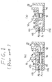
- Spring 70 causes a pressure loss when the fluid gas flows through bypass passage 40 in to suction chamber since spring 70 for biasing shuttle 60 open is disposed in bypass passage 40.
- DE-A-3739978 discloses a variable displacement scroll type compressor including a housing having a fluid suction port and a fluid discharge port; a fixed scroll member having a first circular end plate and a first spiral element extending from one end of the first circular end plate, a discharge hole formed at a central portion of the first circular end plate, the fixed scroll member fixedly disposed in the housing; an orbiting scroll member having a second circular end plate and a second spiral element which extends from one end of the second circular end plate; a driving mechanism to effect the orbital motion of the orbiting scroll member, and a rotation-preventing mechanism for preventing the rotation of the orbiting scroll member during its orbital motion whereby the volume of sealed-off fluid pockets change; a suction chamber formed between an outer peripheral surface of the fixed scroll member and the orbiting scroll member and an inner peripheral surface of the housing, and being communicated with the fluid suction port; a discharge chamber communicated with the discharge hole and the fluid discharge port; at least one bypass passage communicating at least one intermediately located fluid pocket with the suction chamber;
- Figure 1 is a cross sectional view of a principal part of a first example of the variable displacement scroll compressor in the prior art, Figure 1(a) shows a open state of the bypass passage and Figure 1(b) is a closed state of the bypass passage.
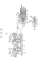
- Figure 2 is a vertical cross-sectional view of a scroll type compressor with a variable displacement mechanism in accordance with one embodiment of this invention.
- Figure 3 is an elevation of a cup-shaped casing of the variable displacement scroll compressor shown in Figure 2.
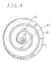
- Figure 4 is an elevation of a fixed scroll member of the variable displacement scroll compressor shown in Figure 2.
- Figure 5 is a rear view of a fixed scroll member of the variable displacement scroll compressor shown in Figure 2.
- Figure 6 is a view of the relationship between front and rear sides of the fixed scroll member shown in Figures 4 and 5.
- Figure 7 is a view of the relationship between a front side of the cup-shaped casing shown in Figure 3 and a rear side of the fixed scroll member shown in Figure 5.
- Figure 8 is a cross sectional view of a principal part of the variable displacement scroll compressor shown in figure 2,
- Figure 8(a) shows a closed state of the bypass passage and Figure 8(b) is an enlarged view of an electromagnetic valve shown in Figure 8(a).
- Figure 9 is a cross sectional view of a principal part of the variable displacement scroll compressor shown in figure 2
- Figure 9(a) shows an open state of the bypass passage
- Figure 9(b) is an enlarged view of an electromagnetic valve shown in Figure 9(a)
- housing 1 is formed of cup-shaped casing 2 and funnel-shaped front end plate 3 which closes an open end of cup-shaped casing 2.
- Cup-shaped casing 2 is provided with a fluid port (not shown) for introducing fluid into housing 1, and fluid discharge port (not shown) for externally discharging the fluid in the housing 1.
- Cup-shaped casing 2 is provided at an inner surface of its one end with a nearly annular rib 4 having a portion 4 lower than the other portion. Rib 4 is provided with four apertures 6 through which bolts 5 are inserted.
- Control pressure passage 7 and groove 8 connecting control pressure 7 are formed in an upper surface of rib 4.
- Cup-shaped casing 2 is provided at its one end with an electromagnetic valve accommodation chamber 9 for accommodating three way electromagnetic valve 80, which will be described later.
- Rib 14 is provided with female threads 16, which engage with bolts 5 inserted through insertion aperture 6 from an outside of the housing 1.
- fixed scroll member 10 is fixedly disposed in housing 1, and discharge chamber 17 is formed between first plate 11 and the end of cup-shaped casing 2.
- Discharge chamber 17 is in communication with discharge port 13 and the fluid outlet port.
- Seal member 18 for maintaining air tightness of discharge chamber 17 is provided between the outer peripheral surface of first plate 11 and the inner peripheral surface of cup-shaped casing 2.
- Orbiting scroll member 20 has second plate 21 of a nearly circular shape, and second spiral member 22 formed on one surface of second plate 21. Orbiting scroll member 20 is assembled with fixed scroll member 10 so that second spiral member 22 is engaged with first scroll member 12 with a phase deviation of 180 degrees. This forms a plurality of fluid pockets 23 between fixed scroll member 10 and orbiting scroll member 20. Second plate 21 is provided at the other surface with boss 24. Bushing 26 is disposed inside boss 24 with needle bearing 25 therebetween. Bushing 26 has an eccentric aperture 26a and a pin 26b. Bushing 26 is provided with counter weight 27 or canceling a centrifugal force by orbiting scroll member 20.
- Rotation preventing thrust bearing mechanism 28 is disposed between second plate 21 and front end plate 3, and prevents the rotation of orbiting scroll member 20 on its axis during revolution thereof along a circular path.
- Fixed scroll member 20 and orbiting scroll member 10 assembled together form a space, i.e., suction chamber 29 between the inner peripheral surface of the cup-shaped casing 2 and the outer peripheral surfaces of fixed scroll member 10 and orbiting scroll member 20.
- Suction chamber 29 is in communication with the fluid inlet port.
- Drive shaft 30 has a small diameter portion 31 and a large diameter portion 32 provided at one end of portion 31.
- Small diameter portion 31 is rotatably supported by ball bearing 33 disposed inside one end of the front end plate 3.
- the large diameter portion 32 is rotatably supported by a ball bearing 34 disposed inside the other end of the front end plate 3, and 32 is provided at an eccentric position with crank pin 35, which is inserted into eccentric aperture 26a in bushing 26.
- crank pin 35 which is inserted into eccentric aperture 26a in bushing 26.
- Large diameter portion 32 is also provided with arc-shaped groove 36 for receiving pin 26b of bushing 26.
- the arc of groove 26 has a center coincident with the center line of crank pin 35.
- bypass passages 40 communicating the fluid pockets 23 with suction chamber 29 are formed of bypass hole 41 formed in first plate 11 and side bypass passage 42 communicating with bypass hole 41.
- Each bypass hole 41 is parallel to an axis of drive shaft 30 (which will merely be referred to as "axis").
- Bypass holes 41 are located so that a pair of fluid pockets 23 communicate with them when those pockets 23 reach the central portions of first and second spiral members 12 and 22.
- Side bypass passage 42 extends in the radial direction of first plate 11, and each has one end 42a configured to receive an end of one end of shuttle valve 60, which will be described later. The other end of each side bypass passage 42 is opened at the outer peripheral surface of first plate 11, and is in communication with suction chamber 29.
- Cylinders 50 which are formed in rib 14 of first plate 11, are coaxial to bypass hole 41 and are in communication with the side bypass passage 42.
- Control pressure passages 7 described before are coaxial with bypass hole 41, and the cylinders 50 are also in communication with these control pressure passages 7.
- Each cylinder 50 has a small diameter portion 50a and a large diameter portion 50b. Small diameter portions 50a directly continue to the ends of side bypass passage 42.
- a shuttle valve 60 having a nearly T-shaped cross section, is slidably disposed in each cylinder 50. Since cylinders 50 are coaxial with bypass hole 41, shuttle valves 60 are also coaxial with the bypass hole 41. An end of each shuttle valve 60 is movable into and away from the end 42a of side bypass passage 42. When the end of shuttle valve 60 moves into the end 42a of side bypass passage 42, bypass passage 40 is closed. When the end of shuttle valve 60 moves away from the end 42a of side bypass passage 42, bypass passage 40 is opened. Seal member 60 is attached around the rear end of each shuttle valve 60.
- Spring 70 is disposed around each shuttle valve 60, and is located in large diameter portion 50b of cylinder 50.
- An end spring 50 is in contact with stepped portion 50c formed between small and large diameter portions 50a and 50b of cylinder 50, and the other end is in contact with the rear end of shuttle valve 60.
- spring 70 biases shuttle valve 60 to move its end away from the end 42a of side bypass passage 42.
- spring 70 biases shuttle valve 60 to open bypass passage 40.
- cup-shaped casing 2 is provided at its one end with passage 92 axially extending from the electromagnetic valve accommodating chamber 9.
- First plate 11 is provided with passage 93 having one end communicating with passage 92 and the other end communicating with side bypass passage 42.
- These passages 92 and 93 as well as side bypass passage 42 form a suction pressure passage communicating suction chamber 29 with third port 83.
- shuttle valve 60 which is moving to open bypass hole 41, receives at its one end the pressure of the fluid which is being compressed in addition to the spring force which biases shuttle valve 60, so that shuttle valve 60 has the superior responsibility as compared with the prior art and thus the responsibility in the displacement controlling operation of the compressor is improved.
- variable displacement scroll compressor of the invention spring 70 biasing shuttle valve 60 is disposed in the cylinder without protruding into bypass hole 41, the pressure loss which is caused by the fluid resistance of spring 70 in the fluid gas in bypass hole 41 can be smaller than one of the prior art, so that the minimum displacement can be precisely obtained.
Landscapes
- Engineering & Computer Science (AREA)
- Mechanical Engineering (AREA)
- General Engineering & Computer Science (AREA)
- Rotary Pumps (AREA)
- Applications Or Details Of Rotary Compressors (AREA)
Claims (5)
- Spiralkompressor variabler Verdrängung mit einem Gehäuse (1) mit einer Fluidansaugöffnung und einer Fluidauslaßöffnung; einem festen Spiralteil (10) mit einer ersten kreisförmigen Endplatte (11) und einem ersten Spiralelement (12), das sich von einem Ende der ersten kreisförmigen Endplatte (11) erstreckt, einem Auslaßloch (13), das an einem Mittelabschnitt der ersten kreisförmigen Endplatte (11) gebildet ist, wobei das feste Spiralteil (10) fest in dem Gehäuse (1) vorgesehen ist; einem umlaufenden Spiralteil (20) mit einer zweiten kreisförmigen Endplatte (21) und einem zweiten Spiralelement (22), das sich von einem Ende der zweiten kreisförmigen Endplatte erstreckt; einem Antriebsmechanismus (30) zum Bewirken der umlaufenden Bewegung des umlaufenden Spiralteiles (20), und einem Rotationsverhinderungsmechanismus (28) zum Verhindern der Rotation des umlaufenden Spiralteiles während seiner umlaufenden Bewegung, wodurch sich das Volumen von abgeschlossenen Fluidtaschen (23) ändert; einer Ansaugkammer (29), die zwischen einer äußeren Umfangsoberfläche des festen Spiralteiles (10) und des umlaufenden Spiralteiles (20) sowie einer inneren Umfangsoberfläche des Gehäuses (1) gebildet ist und in Verbindung mit der Fluidansaugöffnung steht; einer Auslaßkammer, die mit dem Auslaßloch (13) und der Fluidauslaßöffnung in Verbindung steht; mindestens einer Umgehungspassage (40, 42), die mindestens eine in der Mitte angeordnete Fluidtasche (23) mit der Ansaugkammer (29) verbindet; einem Zylinder (50), der mit jeder mindestens einen Umgehungspassage (40) verknüpft ist und innerhalb der mindestens einen Umgehungspassage (40) gebildet ist; einem Ventilteil (60), das mit jeder mindestens einen Umgehungspassage (40) verknüpft ist, ein erstes axiales Ende und ein zweites axiales Ende aufweist und innerhalb von jedem mindestens einen Zylinder (50) so vorgesehen ist, daß es jede mindestens eine Umgehungspassage (40, 42) schließt und öffnet; und einem elastischen Teil (70), das jedes mindestens eine Ventilteil (60) zum Drücken von jedem mindestens einem Ventilteil (60) so vorspannt, daß es jede mindestens eine Umgehungspassage (40, 42) öffnet; wobei jeder mindestens eine Zylinder (50) so angeordnet ist, daß er jedes mindestens eine Ventilteil Druck in jeder mindestens einen in der Mitte angeordneten abgeschlossenen Fluidtaschen (23) an dem ersten axialen Ende davon aufnehmen läßt; wobei das Verbindungssteuermittel (80) selektiv eine Verbindung zwischen der Ansaugkammer (29) und einem Hohlraum, der durch das zweite axiale Ende von jedem Ventilteil und jedem mindestens einen Zylinder (50) definiert wird, und eine Verbindung zwischen der Auslaßkammer und dem Hohlraum steuert;
dadurch gekennzeichnet, daß das elastische Teil (70) um das mindestens eine Ventilteil (60) und innerhalb des Zylinders (50) vorgesehen ist, ohne daß es in die mindestens eine Umgehungspassage (42) vorsteht. - Spiralkompressor nach Anspruch 1, bei dem das Verbindungssteuermittel ein elektromagnetisches Dreiwegeventil (80) ist.
- Spiralkompressor nach Anspruch 1 oder nach Anspruch 2, bei dem die mindestens eine Umgehungspassage (40) ein Paar von Umgehungspassagen (42) aufweist, die einem Paar von den in der Mitte angeordneten abgedichteten Fluidtaschen (23) entsprechen.
- Spiralkompressor nach Anspruch 3, bei dem das feste Spiralteil (10) weiter einen Vorsprung (14) aufweist, der von einem anderen Ende der ersten kreisförmigen Endplatte (11) gegenüber dem ersten Spiralelement (12) vorsteht, wobei der Vorsprung (14) eine Endoberfläche aufweist, die einer inneren Bodenendoberfläche des Gehäuses (1) zugewandt ist, die Zylinder (50) in dem Vorsprung (14) gebildet sind, ein Verbindungsweg (15) den Hohlraum eines jeden der Zylinder (50) verbindet, der Verbindungsweg (15) zwischen der Endoberfläche des Vorsprunges (14) und der inneren Bodenendoberfläche des Gehäuses (1) gebildet ist.
- Spiralkompressor nach Anspruch 4, bei dem der Verbindungsweg (15) eine Rille (8) ist, die an der inneren Bodenendoberfläche des Gehäuses (1) gebildet ist.
Applications Claiming Priority (2)
| Application Number | Priority Date | Filing Date | Title |
|---|---|---|---|
| JP30664/92 | 1992-02-18 | ||
| JP04030664A JP3100452B2 (ja) | 1992-02-18 | 1992-02-18 | 容量可変型スクロール圧縮機 |
Publications (2)
| Publication Number | Publication Date |
|---|---|
| EP0557023A1 EP0557023A1 (de) | 1993-08-25 |
| EP0557023B1 true EP0557023B1 (de) | 1997-01-15 |
Family
ID=12310012
Family Applications (1)
| Application Number | Title | Priority Date | Filing Date |
|---|---|---|---|
| EP93301025A Expired - Lifetime EP0557023B1 (de) | 1992-02-18 | 1993-02-12 | Spiralverdichter mit Einrichtung zur Änderung der Verdrängung |
Country Status (7)
| Country | Link |
|---|---|
| US (1) | US5336058A (de) |
| EP (1) | EP0557023B1 (de) |
| JP (1) | JP3100452B2 (de) |
| KR (1) | KR100225198B1 (de) |
| AU (1) | AU664066B2 (de) |
| CA (1) | CA2089783C (de) |
| DE (1) | DE69307354T2 (de) |
Cited By (8)
| Publication number | Priority date | Publication date | Assignee | Title |
|---|---|---|---|---|
| US7290398B2 (en) | 2003-08-25 | 2007-11-06 | Computer Process Controls, Inc. | Refrigeration control system |
| US7594407B2 (en) | 2005-10-21 | 2009-09-29 | Emerson Climate Technologies, Inc. | Monitoring refrigerant in a refrigeration system |
| US7596959B2 (en) | 2005-10-21 | 2009-10-06 | Emerson Retail Services, Inc. | Monitoring compressor performance in a refrigeration system |
| US7644591B2 (en) | 2001-05-03 | 2010-01-12 | Emerson Retail Services, Inc. | System for remote refrigeration monitoring and diagnostics |
| US7665315B2 (en) | 2005-10-21 | 2010-02-23 | Emerson Retail Services, Inc. | Proofing a refrigeration system operating state |
| US7752854B2 (en) | 2005-10-21 | 2010-07-13 | Emerson Retail Services, Inc. | Monitoring a condenser in a refrigeration system |
| US7752853B2 (en) | 2005-10-21 | 2010-07-13 | Emerson Retail Services, Inc. | Monitoring refrigerant in a refrigeration system |
| US7885959B2 (en) | 2005-02-21 | 2011-02-08 | Computer Process Controls, Inc. | Enterprise controller display method |
Families Citing this family (67)
| Publication number | Priority date | Publication date | Assignee | Title |
|---|---|---|---|---|
| US5591014A (en) * | 1993-11-29 | 1997-01-07 | Copeland Corporation | Scroll machine with reverse rotation protection |
| US5607288A (en) * | 1993-11-29 | 1997-03-04 | Copeland Corporation | Scroll machine with reverse rotation protection |
| US5803716A (en) * | 1993-11-29 | 1998-09-08 | Copeland Corporation | Scroll machine with reverse rotation protection |
| ES2247600T3 (es) * | 1995-06-07 | 2006-03-01 | Copeland Corporation | Maquina helicoidal de capacidad modulada. |
| US5741120A (en) * | 1995-06-07 | 1998-04-21 | Copeland Corporation | Capacity modulated scroll machine |
| JP3549631B2 (ja) * | 1995-06-26 | 2004-08-04 | サンデン株式会社 | 可変容量型スクロール圧縮機 |
| JP3591101B2 (ja) * | 1995-12-19 | 2004-11-17 | ダイキン工業株式会社 | スクロール形流体機械 |
| JP3723283B2 (ja) * | 1996-06-25 | 2005-12-07 | サンデン株式会社 | スクロール型可変容量圧縮機 |
| US5929318A (en) * | 1997-05-02 | 1999-07-27 | Illinois Instruments, Inc. | System and method for sensing low levels of a particular gas in an atmosphere |
| JP3767129B2 (ja) * | 1997-10-27 | 2006-04-19 | 株式会社デンソー | 可変容量圧縮機 |
| US6120255A (en) * | 1998-01-16 | 2000-09-19 | Copeland Corporation | Scroll machine with capacity modulation |
| US6116867A (en) * | 1998-01-16 | 2000-09-12 | Copeland Corporation | Scroll machine with capacity modulation |
| JPH11210650A (ja) * | 1998-01-28 | 1999-08-03 | Sanden Corp | スクロール型圧縮機 |
| JP3707242B2 (ja) * | 1998-05-15 | 2005-10-19 | 株式会社デンソー | 可変容量型圧縮機 |
| US6478550B2 (en) | 1998-06-12 | 2002-11-12 | Daikin Industries, Ltd. | Multi-stage capacity-controlled scroll compressor |
| JP2974009B1 (ja) * | 1998-06-12 | 1999-11-08 | ダイキン工業株式会社 | 多段階容量制御スクロール圧縮機 |
| JP2000087882A (ja) * | 1998-09-11 | 2000-03-28 | Sanden Corp | スクロール型圧縮機 |
| US6505475B1 (en) | 1999-08-20 | 2003-01-14 | Hudson Technologies Inc. | Method and apparatus for measuring and improving efficiency in refrigeration systems |
| US6267565B1 (en) | 1999-08-25 | 2001-07-31 | Copeland Corporation | Scroll temperature protection |
| US6293767B1 (en) | 2000-02-28 | 2001-09-25 | Copeland Corporation | Scroll machine with asymmetrical bleed hole |
| JP4597358B2 (ja) | 2000-12-22 | 2010-12-15 | 株式会社日本自動車部品総合研究所 | スクロール型圧縮機 |
| US6457948B1 (en) | 2001-04-25 | 2002-10-01 | Copeland Corporation | Diagnostic system for a compressor |
| US6668240B2 (en) | 2001-05-03 | 2003-12-23 | Emerson Retail Services Inc. | Food quality and safety model for refrigerated food |
| DE10318626A1 (de) * | 2002-04-25 | 2003-11-13 | Sanden Corp | Kompressor variabler Kapazität |
| US6889173B2 (en) | 2002-10-31 | 2005-05-03 | Emerson Retail Services Inc. | System for monitoring optimal equipment operating parameters |
| US8463441B2 (en) | 2002-12-09 | 2013-06-11 | Hudson Technologies, Inc. | Method and apparatus for optimizing refrigeration systems |
| US6821092B1 (en) | 2003-07-15 | 2004-11-23 | Copeland Corporation | Capacity modulated scroll compressor |
| US7412842B2 (en) | 2004-04-27 | 2008-08-19 | Emerson Climate Technologies, Inc. | Compressor diagnostic and protection system |
| US7275377B2 (en) | 2004-08-11 | 2007-10-02 | Lawrence Kates | Method and apparatus for monitoring refrigerant-cycle systems |
| KR100664058B1 (ko) * | 2004-11-04 | 2007-01-03 | 엘지전자 주식회사 | 스크롤 압축기의 용량 가변장치 |
| US20070036661A1 (en) * | 2005-08-12 | 2007-02-15 | Copeland Corporation | Capacity modulated scroll compressor |
| US8590325B2 (en) | 2006-07-19 | 2013-11-26 | Emerson Climate Technologies, Inc. | Protection and diagnostic module for a refrigeration system |
| US20080216494A1 (en) | 2006-09-07 | 2008-09-11 | Pham Hung M | Compressor data module |
| US7547202B2 (en) * | 2006-12-08 | 2009-06-16 | Emerson Climate Technologies, Inc. | Scroll compressor with capacity modulation |
| US20090071183A1 (en) * | 2007-07-02 | 2009-03-19 | Christopher Stover | Capacity modulated compressor |
| US20090037142A1 (en) | 2007-07-30 | 2009-02-05 | Lawrence Kates | Portable method and apparatus for monitoring refrigerant-cycle systems |
| US8356987B2 (en) * | 2007-09-11 | 2013-01-22 | Emerson Climate Technologies, Inc. | Compressor with retaining mechanism |
| US8393169B2 (en) | 2007-09-19 | 2013-03-12 | Emerson Climate Technologies, Inc. | Refrigeration monitoring system and method |
| CN201972923U (zh) | 2007-10-24 | 2011-09-14 | 艾默生环境优化技术有限公司 | 涡旋机 |
| US9140728B2 (en) | 2007-11-02 | 2015-09-22 | Emerson Climate Technologies, Inc. | Compressor sensor module |
| US8160827B2 (en) | 2007-11-02 | 2012-04-17 | Emerson Climate Technologies, Inc. | Compressor sensor module |
| WO2009091996A2 (en) * | 2008-01-16 | 2009-07-23 | Emerson Climate Technologies, Inc. | Scroll machine |
| KR101280915B1 (ko) * | 2008-05-30 | 2013-07-02 | 에머슨 클리메이트 테크놀로지즈 인코퍼레이티드 | 용량조절 시스템을 가진 압축기 |
| US7976295B2 (en) | 2008-05-30 | 2011-07-12 | Emerson Climate Technologies, Inc. | Compressor having capacity modulation system |
| CN102418698B (zh) | 2008-05-30 | 2014-12-10 | 艾默生环境优化技术有限公司 | 具有包括活塞致动的输出调节组件的压缩机 |
| US8328531B2 (en) * | 2009-01-22 | 2012-12-11 | Danfoss Scroll Technologies, Llc | Scroll compressor with three-step capacity control |
| US8616014B2 (en) | 2009-05-29 | 2013-12-31 | Emerson Climate Technologies, Inc. | Compressor having capacity modulation or fluid injection systems |
| US8568118B2 (en) * | 2009-05-29 | 2013-10-29 | Emerson Climate Technologies, Inc. | Compressor having piston assembly |
| WO2010138831A2 (en) | 2009-05-29 | 2010-12-02 | Emerson Retail Services, Inc. | System and method for monitoring and evaluating equipment operating parameter modifications |
| US8840384B2 (en) * | 2009-09-08 | 2014-09-23 | Danfoss Scroll Technologies, Llc | Scroll compressor capacity modulation with solenoid mounted outside a compressor shell |
| US8308448B2 (en) * | 2009-12-08 | 2012-11-13 | Danfoss Scroll Technologies Llc | Scroll compressor capacity modulation with hybrid solenoid and fluid control |
| CA2828740C (en) | 2011-02-28 | 2016-07-05 | Emerson Electric Co. | Residential solutions hvac monitoring and diagnosis |
| US8964338B2 (en) | 2012-01-11 | 2015-02-24 | Emerson Climate Technologies, Inc. | System and method for compressor motor protection |
| US9480177B2 (en) | 2012-07-27 | 2016-10-25 | Emerson Climate Technologies, Inc. | Compressor protection module |
| US9310439B2 (en) | 2012-09-25 | 2016-04-12 | Emerson Climate Technologies, Inc. | Compressor having a control and diagnostic module |
| CA2904734C (en) | 2013-03-15 | 2018-01-02 | Emerson Electric Co. | Hvac system remote monitoring and diagnosis |
| US9551504B2 (en) | 2013-03-15 | 2017-01-24 | Emerson Electric Co. | HVAC system remote monitoring and diagnosis |
| US9803902B2 (en) | 2013-03-15 | 2017-10-31 | Emerson Climate Technologies, Inc. | System for refrigerant charge verification using two condenser coil temperatures |
| AU2014248049B2 (en) | 2013-04-05 | 2018-06-07 | Emerson Climate Technologies, Inc. | Heat-pump system with refrigerant charge diagnostics |
| US20150004039A1 (en) * | 2013-06-28 | 2015-01-01 | Emerson Climate Technologies, Inc. | Capacity-modulated scroll compressor |
| CN103696960B (zh) * | 2014-01-10 | 2017-01-04 | 上汽通用五菱汽车股份有限公司 | 一种压缩机排气腔组件 |
| US9739277B2 (en) * | 2014-05-15 | 2017-08-22 | Emerson Climate Technologies, Inc. | Capacity-modulated scroll compressor |
| KR102310647B1 (ko) | 2014-12-12 | 2021-10-12 | 삼성전자주식회사 | 압축기 |
| CN106481554B (zh) * | 2015-09-01 | 2019-03-08 | 珠海格力节能环保制冷技术研究中心有限公司 | 变容涡旋压缩机及具有其的空调器 |
| KR102403948B1 (ko) * | 2017-01-03 | 2022-05-31 | 엘지전자 주식회사 | 스크롤 압축기 |
| KR102469601B1 (ko) | 2017-01-26 | 2022-11-22 | 엘지전자 주식회사 | 스크롤 압축기 |
| US11656003B2 (en) | 2019-03-11 | 2023-05-23 | Emerson Climate Technologies, Inc. | Climate-control system having valve assembly |
Family Cites Families (20)
| Publication number | Priority date | Publication date | Assignee | Title |
|---|---|---|---|---|
| DE1035170B (de) * | 1957-03-30 | 1958-07-31 | Fichtel & Sachs Ag | Anlasshilfe fuer Kaelteverdichter |
| US3759057A (en) * | 1972-01-10 | 1973-09-18 | Westinghouse Electric Corp | Room air conditioner having compressor with variable capacity and control therefor |
| JPS5776287A (en) * | 1980-10-31 | 1982-05-13 | Hitachi Ltd | Scroll compressor |
| US4383805A (en) * | 1980-11-03 | 1983-05-17 | The Trane Company | Gas compressor of the scroll type having delayed suction closing capacity modulation |
| US4459817A (en) * | 1980-12-16 | 1984-07-17 | Nippon Soken, Inc. | Rotary compressor |
| JPS5928083A (ja) * | 1982-08-07 | 1984-02-14 | Sanden Corp | スクロ−ル型圧縮機 |
| JPS60101295A (ja) * | 1983-11-08 | 1985-06-05 | Sanden Corp | 圧縮容量可変型のスクロ−ル型圧縮機 |
| JPH0641756B2 (ja) * | 1985-06-18 | 1994-06-01 | サンデン株式会社 | 容量可変型のスクロール型圧縮機 |
| EP0211672B1 (de) * | 1985-08-10 | 1990-10-17 | Sanden Corporation | Spiralverdichter mit Einrichtung zur Verdrängungsregelung |
| JPS6291680A (ja) * | 1985-10-17 | 1987-04-27 | Sanden Corp | 可変容量型スクロ−ル圧縮機 |
| JP2631649B2 (ja) * | 1986-11-27 | 1997-07-16 | 三菱電機株式会社 | スクロール圧縮機 |
| JPS63212789A (ja) * | 1987-02-28 | 1988-09-05 | Sanden Corp | 可変容量型スクロ−ル圧縮機 |
| JPH0756274B2 (ja) * | 1987-03-20 | 1995-06-14 | サンデン株式会社 | スクロール式圧縮機 |
| JPH0744775Y2 (ja) * | 1987-03-26 | 1995-10-11 | 三菱重工業株式会社 | 圧縮機の容量制御装置 |
| JPH0615872B2 (ja) * | 1987-06-30 | 1994-03-02 | サンデン株式会社 | 可変容量型スクロ−ル圧縮機 |
| JP2550612B2 (ja) * | 1987-10-19 | 1996-11-06 | ダイキン工業株式会社 | スクロール形圧縮機の容量制御機構 |
| JPH0746787Y2 (ja) * | 1987-12-08 | 1995-10-25 | サンデン株式会社 | 可変容量型スクロール圧縮機 |
| JP2741709B2 (ja) * | 1988-06-20 | 1998-04-22 | ダイキン工業株式会社 | 可変容量形スクロール圧縮機 |
| JP2780301B2 (ja) * | 1989-02-02 | 1998-07-30 | 株式会社豊田自動織機製作所 | スクロール型圧縮機における容量可変機構 |
| JPH0772544B2 (ja) * | 1989-09-05 | 1995-08-02 | ダイキン工業株式会社 | スクロール形圧縮機 |
-
1992
- 1992-02-18 JP JP04030664A patent/JP3100452B2/ja not_active Expired - Lifetime
-
1993
- 1993-02-11 AU AU32954/93A patent/AU664066B2/en not_active Expired
- 1993-02-12 DE DE69307354T patent/DE69307354T2/de not_active Expired - Lifetime
- 1993-02-12 EP EP93301025A patent/EP0557023B1/de not_active Expired - Lifetime
- 1993-02-18 CA CA002089783A patent/CA2089783C/en not_active Expired - Lifetime
- 1993-02-18 KR KR1019930002224A patent/KR100225198B1/ko not_active Expired - Lifetime
- 1993-02-18 US US08/019,281 patent/US5336058A/en not_active Expired - Lifetime
Cited By (9)
| Publication number | Priority date | Publication date | Assignee | Title |
|---|---|---|---|---|
| US7644591B2 (en) | 2001-05-03 | 2010-01-12 | Emerson Retail Services, Inc. | System for remote refrigeration monitoring and diagnostics |
| US7290398B2 (en) | 2003-08-25 | 2007-11-06 | Computer Process Controls, Inc. | Refrigeration control system |
| US7885959B2 (en) | 2005-02-21 | 2011-02-08 | Computer Process Controls, Inc. | Enterprise controller display method |
| US7885961B2 (en) | 2005-02-21 | 2011-02-08 | Computer Process Controls, Inc. | Enterprise control and monitoring system and method |
| US7594407B2 (en) | 2005-10-21 | 2009-09-29 | Emerson Climate Technologies, Inc. | Monitoring refrigerant in a refrigeration system |
| US7596959B2 (en) | 2005-10-21 | 2009-10-06 | Emerson Retail Services, Inc. | Monitoring compressor performance in a refrigeration system |
| US7665315B2 (en) | 2005-10-21 | 2010-02-23 | Emerson Retail Services, Inc. | Proofing a refrigeration system operating state |
| US7752854B2 (en) | 2005-10-21 | 2010-07-13 | Emerson Retail Services, Inc. | Monitoring a condenser in a refrigeration system |
| US7752853B2 (en) | 2005-10-21 | 2010-07-13 | Emerson Retail Services, Inc. | Monitoring refrigerant in a refrigeration system |
Also Published As
| Publication number | Publication date |
|---|---|
| US5336058A (en) | 1994-08-09 |
| KR930018161A (ko) | 1993-09-21 |
| AU664066B2 (en) | 1995-11-02 |
| EP0557023A1 (de) | 1993-08-25 |
| AU3295493A (en) | 1993-08-19 |
| JPH05231353A (ja) | 1993-09-07 |
| DE69307354T2 (de) | 1997-06-05 |
| CA2089783C (en) | 1999-02-16 |
| CA2089783A1 (en) | 1993-08-19 |
| DE69307354D1 (de) | 1997-02-27 |
| JP3100452B2 (ja) | 2000-10-16 |
| KR100225198B1 (ko) | 1999-10-15 |
Similar Documents
| Publication | Publication Date | Title |
|---|---|---|
| EP0557023A1 (de) | Spiralverdichter mit Einrichtung zur Änderung der Verdrängung | |
| EP0969209B1 (de) | Spiralverdichter mit veränderlicher Förderleistung | |
| US5993177A (en) | Scroll type compressor with improved variable displacement mechanism | |
| EP0486120B1 (de) | Spiralverdichter | |
| US4886425A (en) | Capacity control device of scroll-type fluid compressor | |
| EP0486121B1 (de) | Spiralverdichter | |
| JP2831193B2 (ja) | スクロール型圧縮機の容量制御機構 | |
| JP3550872B2 (ja) | 容量制御スクロール圧縮機 | |
| US4904164A (en) | Scroll type compressor with variable displacement mechanism | |
| US6428286B1 (en) | Capacity control scroll compressor | |
| EP0206759A1 (de) | Verdichter mit ineinander greifenden Spiralelementen | |
| JPH09264250A (ja) | 強制リデュース装置及びそれを備えた圧縮機 | |
| EP0503629A1 (de) | Spiralverdichter mit Einrichtung zur Veränderung der Verdrängung | |
| JPS63109295A (ja) | ベ−ン型回転圧縮機 | |
| US5236316A (en) | Scroll type compressor | |
| KR100306069B1 (ko) | 무마모실린더를구비한용량-제어기구를갖는압축기 | |
| JPS63212789A (ja) | 可変容量型スクロ−ル圧縮機 | |
| CN101044322B (zh) | 具有可选出口压力的泵 | |
| JPH11148472A (ja) | スクロール型圧縮機 | |
| JP3607306B2 (ja) | 可変容量形ポンプ | |
| JP2901267B2 (ja) | 容量可変型スクロール型圧縮機 | |
| JPH0419397B2 (de) | ||
| JPH03194188A (ja) | 容量可変スクロール型圧縮機 | |
| JPS62265491A (ja) | ベ−ン型圧縮機 | |
| JPH04194392A (ja) | コントロールバルブの取付構造 |
Legal Events
| Date | Code | Title | Description |
|---|---|---|---|
| PUAI | Public reference made under article 153(3) epc to a published international application that has entered the european phase |
Free format text: ORIGINAL CODE: 0009012 |
|
| AK | Designated contracting states |
Kind code of ref document: A1 Designated state(s): DE FR GB IT SE |
|
| 17P | Request for examination filed |
Effective date: 19940222 |
|
| 17Q | First examination report despatched |
Effective date: 19950516 |
|
| GRAG | Despatch of communication of intention to grant |
Free format text: ORIGINAL CODE: EPIDOS AGRA |
|
| GRAH | Despatch of communication of intention to grant a patent |
Free format text: ORIGINAL CODE: EPIDOS IGRA |
|
| GRAH | Despatch of communication of intention to grant a patent |
Free format text: ORIGINAL CODE: EPIDOS IGRA |
|
| GRAA | (expected) grant |
Free format text: ORIGINAL CODE: 0009210 |
|
| AK | Designated contracting states |
Kind code of ref document: B1 Designated state(s): DE FR GB IT SE |
|
| ET | Fr: translation filed | ||
| ITF | It: translation for a ep patent filed | ||
| REF | Corresponds to: |
Ref document number: 69307354 Country of ref document: DE Date of ref document: 19970227 |
|
| PLBE | No opposition filed within time limit |
Free format text: ORIGINAL CODE: 0009261 |
|
| STAA | Information on the status of an ep patent application or granted ep patent |
Free format text: STATUS: NO OPPOSITION FILED WITHIN TIME LIMIT |
|
| 26N | No opposition filed | ||
| REG | Reference to a national code |
Ref country code: GB Ref legal event code: IF02 |
|
| PGFP | Annual fee paid to national office [announced via postgrant information from national office to epo] |
Ref country code: FR Payment date: 20120203 Year of fee payment: 20 |
|
| PGFP | Annual fee paid to national office [announced via postgrant information from national office to epo] |
Ref country code: DE Payment date: 20120229 Year of fee payment: 20 |
|
| PGFP | Annual fee paid to national office [announced via postgrant information from national office to epo] |
Ref country code: SE Payment date: 20120207 Year of fee payment: 20 Ref country code: IT Payment date: 20120222 Year of fee payment: 20 Ref country code: GB Payment date: 20120127 Year of fee payment: 20 |
|
| REG | Reference to a national code |
Ref country code: DE Ref legal event code: R071 Ref document number: 69307354 Country of ref document: DE |
|
| REG | Reference to a national code |
Ref country code: GB Ref legal event code: PE20 Expiry date: 20130211 |
|
| REG | Reference to a national code |
Ref country code: SE Ref legal event code: EUG |
|
| PG25 | Lapsed in a contracting state [announced via postgrant information from national office to epo] |
Ref country code: DE Free format text: LAPSE BECAUSE OF EXPIRATION OF PROTECTION Effective date: 20130213 Ref country code: GB Free format text: LAPSE BECAUSE OF EXPIRATION OF PROTECTION Effective date: 20130211 |