EP0558934B2 - Verfahren und Vorrichtung zum Einsparen von elektrischer Energie für den Antrieb eines hydraulischen Aufzuges - Google Patents
Verfahren und Vorrichtung zum Einsparen von elektrischer Energie für den Antrieb eines hydraulischen Aufzuges Download PDFInfo
- Publication number
- EP0558934B2 EP0558934B2 EP93101500A EP93101500A EP0558934B2 EP 0558934 B2 EP0558934 B2 EP 0558934B2 EP 93101500 A EP93101500 A EP 93101500A EP 93101500 A EP93101500 A EP 93101500A EP 0558934 B2 EP0558934 B2 EP 0558934B2
- Authority
- EP
- European Patent Office
- Prior art keywords
- cylinder
- pressure
- speed
- pump
- lift
- Prior art date
- Legal status (The legal status is an assumption and is not a legal conclusion. Google has not performed a legal analysis and makes no representation as to the accuracy of the status listed.)
- Expired - Lifetime
Links
Images
Classifications
-
- B—PERFORMING OPERATIONS; TRANSPORTING
- B66—HOISTING; LIFTING; HAULING
- B66B—ELEVATORS; ESCALATORS OR MOVING WALKWAYS
- B66B1/00—Control systems of elevators in general
- B66B1/24—Control systems with regulation, i.e. with retroactive action, for influencing travelling speed, acceleration, or deceleration
-
- Y—GENERAL TAGGING OF NEW TECHNOLOGICAL DEVELOPMENTS; GENERAL TAGGING OF CROSS-SECTIONAL TECHNOLOGIES SPANNING OVER SEVERAL SECTIONS OF THE IPC; TECHNICAL SUBJECTS COVERED BY FORMER USPC CROSS-REFERENCE ART COLLECTIONS [XRACs] AND DIGESTS
- Y02—TECHNOLOGIES OR APPLICATIONS FOR MITIGATION OR ADAPTATION AGAINST CLIMATE CHANGE
- Y02B—CLIMATE CHANGE MITIGATION TECHNOLOGIES RELATED TO BUILDINGS, e.g. HOUSING, HOUSE APPLIANCES OR RELATED END-USER APPLICATIONS
- Y02B50/00—Energy efficient technologies in elevators, escalators and moving walkways, e.g. energy saving or recuperation technologies
Definitions
- the invention relates to a method and an apparatus for Saving electrical energy for driving a hydraulic elevator, in which a pressure medium under Use of an electric motor driven Hydraulic pump from a tank through a main line a cylinder is pumped up to the elevator move, and in which the pressure medium from the cylinder over Control or lowering valve flows back into the container to move the elevator down.
- DE-OS 40 34 666 a hydraulic elevator with low energy consumption has become known, which is driven by an inverter energy source and has a master cylinder with a stamp and an elevator car and an auxiliary or compensating cylinder with a fixed balance weight and a selectable balance weight.
- the two cylinders are connected to each other by a hydraulic pump.
- the fixed balance weight normally corresponds to the dead weight of the elevator car, while the selectable balance weight is provided so that it corresponds to approximately half the maximum load in the elevator car. This keeps the pressure difference between the main elevator and the compensating elevator as low as possible with all loads.
- the design of the drive size thus depends on the difference between the load on the compensating elevator and the main elevator.
- a disadvantage of this hydraulic elevator is that an additional auxiliary cylinder with a fixed and a selectable balance weight, the necessary connecting line, as well as a relatively complex inverter energy source required are.
- the invention has for its object a method and a device for saving electrical energy for propose the drive of a hydraulic elevator, which with practically constant energy requirements and practically constant, good efficiency.
- the advantages achieved by the invention are in essential to see in that the hydraulic elevator at every load with constant, constant performance and good efficiency is driven, the nominal stroke speed the most common experience Loading of the elevator car, for example, with 2 people is reached, and at idle a greater and at Full load sets a lower lifting speed, and that for any compensation of the delivery rate, the Lowering speed via a valve system, also in Dependency of the load is regulated so that at higher load the lowering speed is increased.
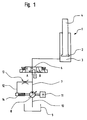
- Fig. 1 denotes a piston-cylinder unit, which has a piston 2 , a cylinder 3 and a piston rod 4 .
- the cylinder 3 is connected on the piston side via a line 5 to the output side of a control or lowering valve 6 .
- the control valve 6 has a working position A for upward operation and a working position B for downward operation.
- the input side of the control valve 6 and the output side of a variable displacement pump 8 are connected to a main line 7 , the input side of the variable displacement pump 8 and a container 9 to an input line 10 .
- the variable displacement pump 8 is driven by an electric motor 11 . Closes on the main pipe 7 a by-pass line 12 which regulating a throttle 13, and a displacement volume of variable displacement pump 8 pressure control valve 14 is connected to the variable displacement pump.
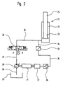
- 21 denotes a piston-cylinder unit, which has a piston 22 , a cylinder 23 and a piston rod 24 .
- the cylinder 23 is connected on the piston side to the outlet side of a control valve 26 via a connecting line 25 .
- the control valve 26 has a working position A for upward operation and a working position B for downward operation.
- the input side of the control valve 26 and the output side of a displacement pump 28 are connected to a main line 27 , the input side of the displacement pump 28 and a container 29 to an input line 30 .
- the displacement pump 28 is driven by an electric motor 31 which is continuously regulated by a frequency converter 32 , depending on the effective load.
- a measuring transducer 33 is connected to the connecting line 25 connecting the cylinder 23 and the control valve 26 with a connecting line 34 .
- the transducer 33 is connected by an electrical line 35 to an amplifier 36 of the frequency converter 32 .
- an elevator car is moved upwards by the piston rod 4 by the variable displacement pump 8 driven by the electric motor 11 , via the main line 7 , via the control valve 6 guided into the working position A and via the Line 5 , oil is pressed into the cylinder 3 of the piston-cylinder unit 1 .
- the variable displacement pump 8 is adjusted by the pressure control valve 14 in accordance with the pressure prevailing in the cylinder 3 of the piston-cylinder unit 1 in such a way that, with constant drive power, the displacement volume of the variable displacement pump 8 results in the travel speed of the elevator car in the upward direction which corresponds to that in corresponds to the load on the elevator car.
- variable displacement pump 8 is adjusted so that the displacement volume of the variable displacement pump and thereby the travel speed of the elevator car decrease in the upward direction with a practically constant drive power.
- the elevator car is in turn moved upwards by the piston rod 24 , by the displacement pump 28 driven by the electric motor 31 via the main line 27 , via the control valve 26 guided into the working position A and via the Line 25 , oil is pressed into the cylinder 23 of the piston-cylinder unit 21 .
- the electric motor 31 is fed and controlled via the frequency converter 32 at a frequency dependent on the load on the elevator car.
- a measuring transducer 33 is connected to the connecting line 34 on the connecting line 25 , which connect the control valve 26 and the cylinder 23 to one another. It absorbs the respective pressure prevailing in the cylinder 23 in accordance with the load present in the elevator car and converts it into a corresponding frequency via the amplifier 36 and the frequency converter 32 .
- the speed of the drive motor 31 for driving the displacement pump 28 is influenced in such a way that when the elevator car is heavily loaded, that is to say at high pressure in the cylinder 23 , a low frequency is set and the displacement pump 28 is driven by the drive motor 31 at a low speed.
- the displacement volume of the displacement pump 28 thereby becomes small, with the drive power remaining practically constant, as does the travel speed of the elevator car in the upward direction.
- the travel speed of the elevator car in the downward direction is controlled by the control or lowering valves 6 or 26 , which are brought into the working position B , in such a way that the lowering speed is increased at higher loads .
Landscapes
- Engineering & Computer Science (AREA)
- Automation & Control Theory (AREA)
- Elevator Control (AREA)
- Fluid-Pressure Circuits (AREA)
- Types And Forms Of Lifts (AREA)
- Forklifts And Lifting Vehicles (AREA)
Description
Die volle Anschlussleistung wird nur dann ausgenutzt, wenn die Aufzugskabine für die volle Tragfähigkeit belastet ist. Bei kleineren Lasten arbeitet der Antrieb mit schlechterem Wirkungsgrad und somit bei verhältnismässig hohem Energieverbrauch.


Es zeigen:
- Fig. 1
- ein Hydraulikschema mit einer Verstellpumpe mit veränderlichem Verdrängungsvolumen in einer Stromrichtung, mit einem stufenlos regulierbaren Druckregelsystem;
- Fig. 2
- ein Hydraulikschema mit einer Verdrängerpumpe, mit konstantem Verdrängungsvolumen, mit frequenzgeregeltem Antriebsmotor, mit stufenloser Anpassung der Motordrehzahl, in Abhängigkeit der effektiv vorhandenen Belastung.
Claims (5)
- Verfahren zum Einsparen von elektrischer Energie für den Antrieb eines hydraulischen Aufzuges, bei welchem ein Druckmittel unter Verwendung einer von einem Elektromotor (11, 31) angetriebenen Hydraulikpumpe (8, 28) aus einem Behälter (9, 29) durch eine Hauptleitung (7, 27) in einen Zylinder (3, 23) gepumpt wird, um den Aufzug aufwärts zu bewegen, und bei welchem das Druckmittel vom Zylinder (3, 23) über ein Steuer- oder Absenkventil (6, 26) in den Behälter (9, 29) zurückfliesst, um den Aufzug abwärts zu bewegen,
wobei die Leistung des Antriebsaggregates bei jeder Belastung der Aufzugskabine durch jeweiliges Anpassen der Fahrgeschwindigkeit in der Aufwärtsrichtung konstant bleibt indem die Fahrgeschwindigkeit für die Aufwärtsfahrt abhängig vom auf das Druckmedium ausgeübten Druck eingestellt wird, welcher durch die Belastung der Aufzugskabine beeinflusst wird. - Verfahren nach Anspruch 1,
dadurch gekennzeichnet,
dass die Fahrgeschwindigkeit für die Aufwärtsfahrt durch den infolge der Belastung der Aufzugskabine auf das Druckmedium ausgeübten Druck eingestellt wird auf die der maximalen Motorleistung entsprechende Volumengeschwindigkeit des Druckmediums. - Verfahren nach Anspruch 1,
dadurch gekennzeichnet,
dass die Fahrgeschwindigkeit für die Aufwärtsfahrt durch den infolge der Belastung der Aufzugskabine auf das Druckmedium ausgeübten Druck eingestellt wird auf die der maximalen Motorleistung entsprechende Drehzahl des Elektromotors (11,31). - Vorrichtung zur Durchführung des Verfahrens gemäss Anspruch 1 und 2, zum Einsparen von elektrischer Energie für den Antrieb eines hydraulischen Antriebes mit einer an einen Elektromotor (11, 31) angeschlossenen Hydraulikpumpe (8, 28), einem Behälter (9, 29) und einer vom Behälter (9, 29) zur Hydraulikpumpe (8, 28) und weiter über ein Steuer- oder Absenkventil (6, 26) zu einem Zylinder (3, 23) einer Kolben-Zylinder-Einheit (1, 21) führenden Leitung (7, 5, 27, 25),
dadurch gekennzeichnet,
dass die Hydraulikpumpe eine Verstellpumpe (8) mit veränderlichem Verdrängungsvolumen ist, und dass zwischen einer Hauptleitung (7) und der Verstellpumpe (8) ein die Verstellpumpe (8) regulierendes Druckegelungsventil (14) angeordnet ist, welches direkt vom Druck des Druck mittels im die Aufzugskabine bewegenden Zylinder 3 beaufschlagt wird. - Vorrichtung zur Durchführung des Verfahrens gemäss Anspruch 1 und 3,
dadurch gekennzeichnet,
dass die Hydraulikpumpe eine Verdrängerpumpe (28) mit konstantem Verdrängungsvolumen ist, und dass an der das Steuerventil (26) mit dem Zylinder (23) verbindenden Leitung (25) ein Messwandler (33) angeordnet ist, welcher abhängig vom Druck im Zylinder (23) über einen Verstärker (36) einen den Elektromotor (31) speisenden Frequenzumformer (32) steuert.
Applications Claiming Priority (3)
| Application Number | Priority Date | Filing Date | Title |
|---|---|---|---|
| CH67092 | 1992-03-04 | ||
| CH670/92 | 1992-03-04 | ||
| CH67092 | 1992-03-04 |
Publications (3)
| Publication Number | Publication Date |
|---|---|
| EP0558934A1 EP0558934A1 (de) | 1993-09-08 |
| EP0558934B1 EP0558934B1 (de) | 1996-08-21 |
| EP0558934B2 true EP0558934B2 (de) | 2000-12-06 |
Family
ID=4192422
Family Applications (1)
| Application Number | Title | Priority Date | Filing Date |
|---|---|---|---|
| EP93101500A Expired - Lifetime EP0558934B2 (de) | 1992-03-04 | 1993-02-01 | Verfahren und Vorrichtung zum Einsparen von elektrischer Energie für den Antrieb eines hydraulischen Aufzuges |
Country Status (16)
| Country | Link |
|---|---|
| US (1) | US5373121A (de) |
| EP (1) | EP0558934B2 (de) |
| JP (1) | JPH05338928A (de) |
| CN (1) | CN1026813C (de) |
| AT (1) | ATE141573T1 (de) |
| AU (1) | AU660068B2 (de) |
| CA (1) | CA2088893C (de) |
| CZ (1) | CZ286024B6 (de) |
| DE (1) | DE59303462D1 (de) |
| DK (1) | DK0558934T4 (de) |
| ES (1) | ES2093289T5 (de) |
| FI (1) | FI112791B (de) |
| HU (1) | HU212112B (de) |
| MX (1) | MX9301151A (de) |
| NO (1) | NO930756L (de) |
| SK (1) | SK279308B6 (de) |
Families Citing this family (15)
| Publication number | Priority date | Publication date | Assignee | Title |
|---|---|---|---|---|
| DE4335403C1 (de) * | 1993-10-18 | 1994-12-15 | Karl Hehl | Hydraulikeinrichtung |
| DE4440420C3 (de) * | 1994-11-07 | 2003-07-24 | Demag Cranes & Components Gmbh | Verfahren und Einrichtung zum Überwachen und/oder Steuern der Drehzahl eines Elektroantriebs mit Frequenzumrichter für Hubwerke |
| DE19511591C2 (de) * | 1995-03-29 | 1997-02-06 | Jungheinrich Ag | Verfahren zur Bestimmung der Last eines Flurförderzeugs |
| US5890562A (en) * | 1996-08-16 | 1999-04-06 | Bt Prime Mover, Inc. | Control console for material handling vehicle |
| KR100510204B1 (ko) * | 1997-02-06 | 2005-11-16 | 부커 하이드롤릭스 아게 | 유압리프트의 제어방법 및 제어장치 |
| US6505711B1 (en) * | 1999-08-25 | 2003-01-14 | Bucher Hydraulics Ag | Hydraulic elevator, comprising a pressure accumulator which acts as a counterweight and a method for controlling and regulating an elevator of this type |
| JP2004003612A (ja) * | 2002-04-09 | 2004-01-08 | Komatsu Ltd | シリンダ駆動システム及びそのエネルギ回生方法 |
| DE10261225B4 (de) * | 2002-12-20 | 2006-11-16 | Dorma Gmbh + Co. Kg | Elektrohydraulischer Servotürantrieb zum Antrieb einer Tür, eines Fensters oder dergleichen |
| US20090099714A1 (en) * | 2007-10-12 | 2009-04-16 | Ajith Kuttannair Kumar | System and method for dynamically determining a force applied through a rail vehicle axle |
| US20090095194A1 (en) * | 2007-10-12 | 2009-04-16 | Ajith Kuttannair Kumar | System and method for dynamically affecting a force applied through a rail vehicle axle |
| DE102012106031B3 (de) * | 2012-07-05 | 2013-07-11 | Römer Fördertechnik GmbH | Elektrohydraulisches Hubgerät sowie Verfahren zur Steuerung des elektrohydraulischen Hubgerätes |
| CN103267038B (zh) * | 2013-05-09 | 2017-02-08 | 洛阳理工学院 | 一种控制多台升降台的液压控制回路 |
| CN104481947A (zh) * | 2014-12-08 | 2015-04-01 | 西南铝业(集团)有限责任公司 | 倾翻炉共用液压控制系统 |
| CN104627837B (zh) * | 2015-02-11 | 2016-06-08 | 河海大学常州校区 | 一种行车精准吊装机具 |
| CN104609315B (zh) * | 2015-02-11 | 2016-06-29 | 河海大学常州校区 | 一种行车精准吊装机具 |
Citations (3)
| Publication number | Priority date | Publication date | Assignee | Title |
|---|---|---|---|---|
| DE1184055B (de) † | 1959-05-27 | 1964-12-23 | Kaemper Motoren G M B H | Hydraulisch angetriebenes Hubwerk |
| DE2658928A1 (de) † | 1976-12-24 | 1978-07-06 | Beringer Hydraulik Gmbh | Hydraulische steuerung |
| DE4036860A1 (de) † | 1989-11-20 | 1991-07-04 | Toyoda Automatic Loom Works | Belastung-/entlastung-steuervorrichtung fuer einen hydraulikkreis |
Family Cites Families (9)
| Publication number | Priority date | Publication date | Assignee | Title |
|---|---|---|---|---|
| CH465805A (de) * | 1967-01-06 | 1968-11-30 | Leipzig Inst Foerdertech | Hydrostatischer Antrieb mit Gegengewichts-System, insbesondere für Aufzüge |
| US3762165A (en) * | 1970-12-07 | 1973-10-02 | Hitachi Ltd | Hydraulic elevator apparatus |
| JPS5326378B2 (de) * | 1972-03-15 | 1978-08-02 | ||
| GB1579834A (en) * | 1976-12-24 | 1980-11-26 | Eimco Grat Britain Ltd | Fluid transmission circuits |
| JPS60246412A (ja) * | 1984-05-21 | 1985-12-06 | Mitsubishi Electric Corp | 運搬装置 |
| NL8701922A (nl) * | 1987-08-14 | 1989-03-01 | Jacobus Leonardus Saam | Energiezuinige hydraulische liftaandrijving met regelbare motor voor beide rijrichtingen (zonder stuurblok). |
| FI83204C (fi) * | 1987-11-04 | 1991-06-10 | Kone Oy | Foerfarande och anordning foer foerbaettring av verkningsgraden hos en motorstyrd hydraulhiss. |
| JP2628397B2 (ja) * | 1990-04-25 | 1997-07-09 | 回生工業株式会社 | インバータ電源を用いた油圧エレベータの速度制御方法 |
| JP2533683B2 (ja) * | 1990-10-16 | 1996-09-11 | 三菱電機株式会社 | 油圧エレベ―タの制御装置 |
-
1993
- 1993-02-01 ES ES93101500T patent/ES2093289T5/es not_active Expired - Lifetime
- 1993-02-01 DE DE59303462T patent/DE59303462D1/de not_active Expired - Fee Related
- 1993-02-01 AT AT93101500T patent/ATE141573T1/de not_active IP Right Cessation
- 1993-02-01 DK DK93101500T patent/DK0558934T4/da not_active Application Discontinuation
- 1993-02-01 EP EP93101500A patent/EP0558934B2/de not_active Expired - Lifetime
- 1993-02-05 CA CA002088893A patent/CA2088893C/en not_active Expired - Lifetime
- 1993-02-11 CZ CZ93178A patent/CZ286024B6/cs not_active IP Right Cessation
- 1993-02-17 HU HU9300433A patent/HU212112B/hu not_active IP Right Cessation
- 1993-02-18 SK SK103-93A patent/SK279308B6/sk unknown
- 1993-03-02 FI FI930918A patent/FI112791B/fi active
- 1993-03-02 MX MX9301151A patent/MX9301151A/es not_active IP Right Cessation
- 1993-03-02 NO NO93930756A patent/NO930756L/no not_active Application Discontinuation
- 1993-03-03 CN CN93102311A patent/CN1026813C/zh not_active Expired - Fee Related
- 1993-03-03 AU AU33920/93A patent/AU660068B2/en not_active Ceased
- 1993-03-04 JP JP5043989A patent/JPH05338928A/ja active Pending
- 1993-03-04 US US08/026,545 patent/US5373121A/en not_active Expired - Lifetime
Patent Citations (3)
| Publication number | Priority date | Publication date | Assignee | Title |
|---|---|---|---|---|
| DE1184055B (de) † | 1959-05-27 | 1964-12-23 | Kaemper Motoren G M B H | Hydraulisch angetriebenes Hubwerk |
| DE2658928A1 (de) † | 1976-12-24 | 1978-07-06 | Beringer Hydraulik Gmbh | Hydraulische steuerung |
| DE4036860A1 (de) † | 1989-11-20 | 1991-07-04 | Toyoda Automatic Loom Works | Belastung-/entlastung-steuervorrichtung fuer einen hydraulikkreis |
Also Published As
| Publication number | Publication date |
|---|---|
| CA2088893C (en) | 2003-11-25 |
| CN1077256A (zh) | 1993-10-13 |
| CZ286024B6 (cs) | 1999-12-15 |
| SK10393A3 (en) | 1993-10-06 |
| DK0558934T3 (da) | 1996-12-23 |
| FI930918A7 (fi) | 1993-09-05 |
| US5373121A (en) | 1994-12-13 |
| DE59303462D1 (de) | 1996-09-26 |
| MX9301151A (es) | 1993-09-01 |
| CZ17893A3 (en) | 1993-11-17 |
| HU9300433D0 (en) | 1993-05-28 |
| SK279308B6 (sk) | 1998-09-09 |
| NO930756D0 (no) | 1993-03-02 |
| CA2088893A1 (en) | 1993-09-05 |
| HUT64610A (en) | 1994-01-28 |
| CN1026813C (zh) | 1994-11-30 |
| FI112791B (fi) | 2004-01-15 |
| JPH05338928A (ja) | 1993-12-21 |
| ES2093289T3 (es) | 1996-12-16 |
| DK0558934T4 (da) | 2001-03-05 |
| HU212112B (en) | 1996-02-28 |
| AU660068B2 (en) | 1995-06-08 |
| EP0558934B1 (de) | 1996-08-21 |
| ES2093289T5 (es) | 2001-04-01 |
| NO930756L (no) | 1993-09-06 |
| AU3392093A (en) | 1993-09-09 |
| EP0558934A1 (de) | 1993-09-08 |
| FI930918A0 (fi) | 1993-03-02 |
| ATE141573T1 (de) | 1996-09-15 |
Similar Documents
| Publication | Publication Date | Title |
|---|---|---|
| EP0558934B2 (de) | Verfahren und Vorrichtung zum Einsparen von elektrischer Energie für den Antrieb eines hydraulischen Aufzuges | |
| DE3515096C2 (de) | Vorrichtung zum Abfedern und Dämpfen der Hubbewegung eines Gesenks | |
| DE3836212C2 (de) | ||
| EP0641644A1 (de) | Verfahren zur Regelung des Antriebs einer hydraulischen Presse und Vorrichtung zur Durchführung des Verfahrens | |
| DE2704107A1 (de) | Verfahren und vorrichtung zur leistungsregelung in hydraulischen und hydraulisch-pneumatischen systemen | |
| DE69007866T2 (de) | Anlage, um eine Pumpvorrichtung zu steuern. | |
| DE102012104125A1 (de) | Verfahren zum Betreiben einer hydraulischen Presse und eine hydraulische Presse | |
| EP1208057B1 (de) | Hydraulischer aufzug mit einem als gegengewicht wirkenden druckspeicher und verfahren zum steuern und regeln eines solchen aufzugs | |
| EP1446349B1 (de) | Hydraulischer aufzug mit einem druckspeicher sowie verfahren zur steuerung und regelung eines solchen aufzugs | |
| DE69817343T2 (de) | Hydraulischer antrieb mit konstantem druck in einer druckleitung | |
| EP3601797A1 (de) | Kolbenkompressor mit erweitertem regelbereich | |
| EP2260210B1 (de) | Steuergerät sowie dessen verwendung | |
| DE2132842A1 (de) | Sicherheitseinrichtung fuer Hubstapler | |
| WO2000009279A1 (de) | Vorrichtung zum hydraulischen anstellen der rollen von strangführungssegmenten einer stranggiessanlage | |
| DE3247004A1 (de) | Hydrostatisches getriebe, insbesondere fuer den fahrzeugantrieb | |
| WO2003042086A1 (de) | Hydraulischer aufzug mit einem druckspeicher sowie verfahren zur steuerung und regelung eines solchen aufzugs | |
| DE19631804B4 (de) | Hydraulische Hubeinrichtung | |
| DE3918119A1 (de) | Anordnung zur betaetigung mindestens eines linearmotors, insbesondere fuer eine dosiereinrichtung | |
| DE3539550A1 (de) | Verfahren zum regeln des hydrostatischen antriebs der mischertrommel eines fahrmischers | |
| DE3321443A1 (de) | Vibrationswalze mit leistungsbegrenzungsvorrichtung | |
| DE2421305A1 (de) | Ueberlastschutzvorrichtung fuer hydrostatische getriebe | |
| DE2751663A1 (de) | Hydrostatische kraftuebertragungsanordnung mit belastungsausgleich | |
| DE69612911T2 (de) | Verfahren für die Regelung von Verdrängungstyp-Fluidmaschinen und Einrichtung hierfür | |
| DE4304403A1 (en) | Hydraulic control system for hydrostatic power transmission - uses two-level pressure limiting valve, and leakage oil circuit | |
| DE2532768A1 (de) | Hydraulisches regelsystem |
Legal Events
| Date | Code | Title | Description |
|---|---|---|---|
| PUAI | Public reference made under article 153(3) epc to a published international application that has entered the european phase |
Free format text: ORIGINAL CODE: 0009012 |
|
| AK | Designated contracting states |
Kind code of ref document: A1 Designated state(s): AT BE CH DE DK ES FR GB IT LI NL SE |
|
| RBV | Designated contracting states (corrected) |
Designated state(s): AT BE CH DE DK ES FR GB IT LI NL SE |
|
| RIN1 | Information on inventor provided before grant (corrected) |
Inventor name: NAGEL, HEINZ-DIETER |
|
| RAP1 | Party data changed (applicant data changed or rights of an application transferred) |
Owner name: INVENTIO AG |
|
| 17P | Request for examination filed |
Effective date: 19940217 |
|
| 17Q | First examination report despatched |
Effective date: 19951109 |
|
| GRAH | Despatch of communication of intention to grant a patent |
Free format text: ORIGINAL CODE: EPIDOS IGRA |
|
| GRAH | Despatch of communication of intention to grant a patent |
Free format text: ORIGINAL CODE: EPIDOS IGRA |
|
| GRAA | (expected) grant |
Free format text: ORIGINAL CODE: 0009210 |
|
| AK | Designated contracting states |
Kind code of ref document: B1 Designated state(s): AT BE CH DE DK ES FR GB IT LI NL SE |
|
| REF | Corresponds to: |
Ref document number: 141573 Country of ref document: AT Date of ref document: 19960915 Kind code of ref document: T |
|
| REF | Corresponds to: |
Ref document number: 59303462 Country of ref document: DE Date of ref document: 19960926 |
|
| GBT | Gb: translation of ep patent filed (gb section 77(6)(a)/1977) |
Effective date: 19960913 |
|
| ET | Fr: translation filed | ||
| ITF | It: translation for a ep patent filed | ||
| REG | Reference to a national code |
Ref country code: ES Ref legal event code: FG2A Ref document number: 2093289 Country of ref document: ES Kind code of ref document: T3 |
|
| REG | Reference to a national code |
Ref country code: DK Ref legal event code: T3 |
|
| PLBQ | Unpublished change to opponent data |
Free format text: ORIGINAL CODE: EPIDOS OPPO |
|
| PLBI | Opposition filed |
Free format text: ORIGINAL CODE: 0009260 |
|
| PLBQ | Unpublished change to opponent data |
Free format text: ORIGINAL CODE: EPIDOS OPPO |
|
| PLAB | Opposition data, opponent's data or that of the opponent's representative modified |
Free format text: ORIGINAL CODE: 0009299OPPO |
|
| PLBF | Reply of patent proprietor to notice(s) of opposition |
Free format text: ORIGINAL CODE: EPIDOS OBSO |
|
| 26 | Opposition filed |
Opponent name: THYSSEN AUFZUEGE GMBH Effective date: 19970521 |
|
| R26 | Opposition filed (corrected) |
Opponent name: THYSSEN AUFZUEGE GMBH Effective date: 19970521 |
|
| NLR1 | Nl: opposition has been filed with the epo |
Opponent name: THYSSEN AUFZUEGE GMBH |
|
| PLBF | Reply of patent proprietor to notice(s) of opposition |
Free format text: ORIGINAL CODE: EPIDOS OBSO |
|
| PLAW | Interlocutory decision in opposition |
Free format text: ORIGINAL CODE: EPIDOS IDOP |
|
| PLAW | Interlocutory decision in opposition |
Free format text: ORIGINAL CODE: EPIDOS IDOP |
|
| PUAH | Patent maintained in amended form |
Free format text: ORIGINAL CODE: 0009272 |
|
| STAA | Information on the status of an ep patent application or granted ep patent |
Free format text: STATUS: PATENT MAINTAINED AS AMENDED |
|
| 27A | Patent maintained in amended form |
Effective date: 20001206 |
|
| AK | Designated contracting states |
Kind code of ref document: B2 Designated state(s): AT BE CH DE DK ES FR GB IT LI NL SE |
|
| REG | Reference to a national code |
Ref country code: CH Ref legal event code: AEN Free format text: AUFRECHTERHALTUNG DES PATENTES IN GEAENDERTER FORM |
|
| NLR2 | Nl: decision of opposition | ||
| GBTA | Gb: translation of amended ep patent filed (gb section 77(6)(b)/1977) | ||
| ET3 | Fr: translation filed ** decision concerning opposition | ||
| ITF | It: translation for a ep patent filed | ||
| REG | Reference to a national code |
Ref country code: DK Ref legal event code: T4 |
|
| REG | Reference to a national code |
Ref country code: ES Ref legal event code: DC2A Kind code of ref document: T5 Effective date: 20010227 |
|
| NLR3 | Nl: receipt of modified translations in the netherlands language after an opposition procedure | ||
| REG | Reference to a national code |
Ref country code: GB Ref legal event code: IF02 |
|
| PGFP | Annual fee paid to national office [announced via postgrant information from national office to epo] |
Ref country code: ES Payment date: 20090219 Year of fee payment: 17 Ref country code: DK Payment date: 20090213 Year of fee payment: 17 Ref country code: AT Payment date: 20090218 Year of fee payment: 17 |
|
| PGFP | Annual fee paid to national office [announced via postgrant information from national office to epo] |
Ref country code: NL Payment date: 20090217 Year of fee payment: 17 Ref country code: DE Payment date: 20090219 Year of fee payment: 17 |
|
| PGFP | Annual fee paid to national office [announced via postgrant information from national office to epo] |
Ref country code: GB Payment date: 20090219 Year of fee payment: 17 |
|
| PGFP | Annual fee paid to national office [announced via postgrant information from national office to epo] |
Ref country code: SE Payment date: 20090216 Year of fee payment: 17 Ref country code: IT Payment date: 20090221 Year of fee payment: 17 |
|
| PGFP | Annual fee paid to national office [announced via postgrant information from national office to epo] |
Ref country code: BE Payment date: 20090408 Year of fee payment: 17 |
|
| PGFP | Annual fee paid to national office [announced via postgrant information from national office to epo] |
Ref country code: FR Payment date: 20090213 Year of fee payment: 17 Ref country code: CH Payment date: 20090515 Year of fee payment: 17 |
|
| BERE | Be: lapsed |
Owner name: *INVENTIO A.G. Effective date: 20100228 |
|
| REG | Reference to a national code |
Ref country code: NL Ref legal event code: V1 Effective date: 20100901 |
|
| REG | Reference to a national code |
Ref country code: CH Ref legal event code: PL |
|
| REG | Reference to a national code |
Ref country code: DK Ref legal event code: EBP |
|
| EUG | Se: european patent has lapsed | ||
| GBPC | Gb: european patent ceased through non-payment of renewal fee |
Effective date: 20100201 |
|
| PG25 | Lapsed in a contracting state [announced via postgrant information from national office to epo] |
Ref country code: LI Free format text: LAPSE BECAUSE OF NON-PAYMENT OF DUE FEES Effective date: 20100228 Ref country code: CH Free format text: LAPSE BECAUSE OF NON-PAYMENT OF DUE FEES Effective date: 20100228 |
|
| REG | Reference to a national code |
Ref country code: FR Ref legal event code: ST Effective date: 20101029 |
|
| PG25 | Lapsed in a contracting state [announced via postgrant information from national office to epo] |
Ref country code: AT Free format text: LAPSE BECAUSE OF NON-PAYMENT OF DUE FEES Effective date: 20100201 |
|
| PG25 | Lapsed in a contracting state [announced via postgrant information from national office to epo] |
Ref country code: NL Free format text: LAPSE BECAUSE OF NON-PAYMENT OF DUE FEES Effective date: 20100901 Ref country code: FR Free format text: LAPSE BECAUSE OF NON-PAYMENT OF DUE FEES Effective date: 20100301 Ref country code: DK Free format text: LAPSE BECAUSE OF NON-PAYMENT OF DUE FEES Effective date: 20100228 |
|
| PG25 | Lapsed in a contracting state [announced via postgrant information from national office to epo] |
Ref country code: DE Free format text: LAPSE BECAUSE OF NON-PAYMENT OF DUE FEES Effective date: 20100901 Ref country code: BE Free format text: LAPSE BECAUSE OF NON-PAYMENT OF DUE FEES Effective date: 20100228 |
|
| REG | Reference to a national code |
Ref country code: ES Ref legal event code: FD2A Effective date: 20110308 |
|
| PG25 | Lapsed in a contracting state [announced via postgrant information from national office to epo] |
Ref country code: GB Free format text: LAPSE BECAUSE OF NON-PAYMENT OF DUE FEES Effective date: 20100201 Ref country code: IT Free format text: LAPSE BECAUSE OF NON-PAYMENT OF DUE FEES Effective date: 20100201 |
|
| PG25 | Lapsed in a contracting state [announced via postgrant information from national office to epo] |
Ref country code: ES Free format text: LAPSE BECAUSE OF NON-PAYMENT OF DUE FEES Effective date: 20110307 |
|
| PG25 | Lapsed in a contracting state [announced via postgrant information from national office to epo] |
Ref country code: ES Free format text: LAPSE BECAUSE OF NON-PAYMENT OF DUE FEES Effective date: 20100202 |
|
| PG25 | Lapsed in a contracting state [announced via postgrant information from national office to epo] |
Ref country code: SE Free format text: LAPSE BECAUSE OF NON-PAYMENT OF DUE FEES Effective date: 20100202 |