EP0560746B1 - Ein zwischen mehreren Regalgängen bewegbares Regalbedienungsgerät - Google Patents
Ein zwischen mehreren Regalgängen bewegbares Regalbedienungsgerät Download PDFInfo
- Publication number
- EP0560746B1 EP0560746B1 EP93850042A EP93850042A EP0560746B1 EP 0560746 B1 EP0560746 B1 EP 0560746B1 EP 93850042 A EP93850042 A EP 93850042A EP 93850042 A EP93850042 A EP 93850042A EP 0560746 B1 EP0560746 B1 EP 0560746B1
- Authority
- EP
- European Patent Office
- Prior art keywords
- crane
- transfer
- drive wheel
- storage
- carriage
- Prior art date
- Legal status (The legal status is an assumption and is not a legal conclusion. Google has not performed a legal analysis and makes no representation as to the accuracy of the status listed.)
- Expired - Lifetime
Links
- 238000005007 materials handling Methods 0.000 claims abstract description 5
- 230000008878 coupling Effects 0.000 claims description 17
- 238000010168 coupling process Methods 0.000 claims description 17
- 238000005859 coupling reaction Methods 0.000 claims description 17
- BTFMCMVEUCGQDX-UHFFFAOYSA-N 1-[10-[3-[4-(2-hydroxyethyl)-1-piperidinyl]propyl]-2-phenothiazinyl]ethanone Chemical compound C12=CC(C(=O)C)=CC=C2SC2=CC=CC=C2N1CCCN1CCC(CCO)CC1 BTFMCMVEUCGQDX-UHFFFAOYSA-N 0.000 claims 1
- 229960004265 piperacetazine Drugs 0.000 claims 1
- 230000000087 stabilizing effect Effects 0.000 abstract description 2
- 230000005540 biological transmission Effects 0.000 description 3
- 238000010276 construction Methods 0.000 description 2
- 230000000694 effects Effects 0.000 description 1
- 230000005484 gravity Effects 0.000 description 1
- 238000012986 modification Methods 0.000 description 1
- 230000004048 modification Effects 0.000 description 1
- 230000003319 supportive effect Effects 0.000 description 1
Images


Classifications
-
- B—PERFORMING OPERATIONS; TRANSPORTING
- B65—CONVEYING; PACKING; STORING; HANDLING THIN OR FILAMENTARY MATERIAL
- B65G—TRANSPORT OR STORAGE DEVICES, e.g. CONVEYORS FOR LOADING OR TIPPING, SHOP CONVEYOR SYSTEMS OR PNEUMATIC TUBE CONVEYORS
- B65G1/00—Storing articles, individually or in orderly arrangement, in warehouses or magazines
- B65G1/02—Storage devices
- B65G1/04—Storage devices mechanical
- B65G1/0407—Storage devices mechanical using stacker cranes
- B65G1/0428—Transfer means for the stacker crane between the alleys
Definitions
- the present invention relates to a materials handling system comprising a railbound storage crane for transporting goods in storage corridors, a transfer carriage for moving the crane transversely between two storage corridors, transfer carriage drive means, and a carrier frame mounted on the transfer carriage and functioning to support and stabilize the crane during its movement between the storage corridors.
- Systems of this kind are used when a storage crane is to handle goods in two or more neighbouring storage corridors.
- the crane is normally supported on two wheels which roll along a rail mounted on the floor of the storage corridor.
- the crane is unstable on the floor-mounted rail and must therefore be stabilized with the aid of a guide mounted on the mast top and running along a ceiling-mounted rail.
- the transfer carriage is intended to move the crane transversely between the storage corridors and as the crane is moved must be capable of supporting and stabilizing the crane when the crane has left the floor-mounted rail and the ceiling-mounted rail.
- such systems are a convenient alternative to the more general construction which includes one storage crane for each storage corridor and particularly in the case of handling materials at average or low frequencies, i.e. when each load unit shall be stored over a period which is somewhat longer than the period normally required to economically justify one crane for each storage corridor.
- the storage crane and the transfer carriage are most often controlled automatically with the aid of different types of control computers.
- U.S. 4,046,267 teaches an arrangement for moving a picker truck between the storage corridors with the aid of a transfer carriage which runs on the same floor level as the truck and is driven by the truck driving motor.
- This system is also relatively intricate and cannot be used for transporting railbound storage cranes, but is totally oriented towards trucks which are driven directly on the floor.
- One object of the present invention is therefore to provide a materials handling system which includes a storage crane and a transfer carriage so constructed as to enable the system to be viable technically and economically within much smaller storage localities than was possible with the earlier known systems. Another object is to simplify the transfer carriage drive and control arrangement. A third object is to provide constructive cooperation between storage crane and transfer carriage such as to enable different floor levels between storage corridors and transfer areas to be avoided and also separate vertical crane control devices mounted on the carriage or along the path travelled thereby.
- One condition for achieving the aim of a more generally usable transfer arrangement is that standard storage locations can be equipped with said arrangement without needing to restructure existing floors, walls and ceilings.
- the inventive solution enables the crane control and drive means to be used to manoeuver the transfer carriage, which can therefore be manufactured as a simple, passive supporting carriage which lacks its own drive motor and drive wheels. Because the crane-carried transfer drive wheel can be moved down into abutment with the transfer carriage support surface and therewith drive the carriage, the need to provide complicated power transmitting coupling devices between the crane drive means and the transfer carriage is obviated.
- a wheel moving device which functions to hold the transfer drive wheel in a raised position during normal work carried out by the crane in the storage corridors and to lower the wheel into abutment with the transfer carriage support surface when advancing the transfer carriage. This enables the crane to be moved along the rail without being impeded or disturbed by a downwardly hanging additional wheel.
- the transfer carriage has two supportive beams which are arranged on a respective side of the crane rail on the carriage in a manner to directly support and stabilize the crane.
- the crane is supported via wheeled support arms which project laterally from the crane chassis. This enables the major part of the weight of the crane to be lowered onto the support beams and to relieve the crane rail from load to a corresponding degree. This will enable the rail to be supported on a thin support pad close to the supporting surface, or foundation surface, so that the rail on the carriage and in the crane corridors can be mounted at essentially the same level.
- the crane drive motor is conveniently arranged to drive the transfer drive wheel with the aid of coupling devices by means of which the driving wheel of the drive motor and the drive wheel of the transfer carriage can be coupled mechanically, and a particular advantage is afforded when this mechanical coupling is effected with the aid of the aforesaid movement device. For instance, this will enable a setting means to be provided for vertical manoeuvering of the transfer drive wheel and for connecting driving power thereto.
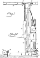
- the illustrated storage crane includes typically a wheeled chassis 11, a vertical chassis-mounted lifting mast 12 and a load carrier 13 which can move along the mast.
- the chassis 11 is carried by a front and a rear wheel 14, 15, of which the rear wheel 15 functions as a drive wheel and is connected to a drive motor 17 via a gearbox 16.
- the wheels are intended to run on a rail 18 which is mounted on the floor 19 of a storage corridor.
- the crane is held stably in a vertical position with the aid of a top guide 20 mounted on the mast top 21.
- the top guide includes two or more runners 22 mounted on a respective side of a top guide beam 23 mounted on the ceiling of the storage corridor.
- the purpose of the crane is to transport load units to and from storage places on the racks located on either side of a storage corridor.
- the crane chassis 11 has a front support arm and a rear support arm 24, 25 fitted thereto.
- the support arms extend perpendicularly to the longitudinal axis of the crane and are provided with support wheels 26, 27, 28 at their respective outer ends, of which wheels the rear support wheels 27, 28 are mounted on a transverse arm 29 on the rear support arm 25.
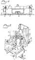
- the purpose of these support arms 24, 25 is to stabilize and support the crane during its movement between two storage corridors, as evident from Figures 2-5.
- the crane is moved between corridors with the aid of a transfer carriage 30 which moves transversely between the parallel corridors, in a conventional manner.
- the transfer carriage is comprised mainly of a horizontal framework which includes a carrier frame 32 which is mounted perpendicularly to a main beam 33 which extends in the direction of the longitudinal axis of the carriage and is stabilized thereagainst with the aid of two inclined support beams 34.
- the carrier frame 32 is intended to receive and support the storage crane and includes two longitudinally extending support beams 35.
- support and guide bars 36 Welded firmly to the upper surface of the support beams 35 are support and guide bars 36 which function as a support surface or foundation surface for the support wheels 26, 27, 28 and as guide bars for recesses 37 in the support arms.
- Mounted between the parallel support beams 35 are a number of flat bars 37' which function to support a rail 38 for crane wheels 14, 15.
- the flat bars 37 are mounted on the undersurfaces of respective support beams 35, so that the rail 38 will be located as close as possible to the foundation surface 39 of the carriage.
- the support wheels 26, 27, 28 rest on the support beams 35 and the front crane wheel 14 rests on the rail 38, while the drive wheel 15 is located over a free space 40 for reasons that will be evident from the following.
- the transfer carriage is supported on two large support wheels 41 and two smaller support wheels 42, these wheels being firmly mounted on the main beam 33 and the carrier frame 32 respectively.
- the carriage is guided by a longitudinally extending guide bar or rail 43 through the agency of side support wheels 44 which are mounted in the proximity of the larger wheels 41.
- the large wheels thus run on the guide rail whereas the smaller wheels 42 run freely on the foundation surfaces or pads 39 in the absence of side guides.
- the smaller wheels are mounted beneath the support beams 35 so as to be located essentially immediately beneath the guide rails 36 and therewith beneath the crane support wheels 26, 27, 28. This will prevent the carrier frame 32 being subjected to other force moments than those originating from the load on the crane rail 38.
- By suitable dimensioning it is possible to transfer 60-90% of the total weight of the crane to the support beams, whereby the residual load on the crane rail 38 will be very small and the flat bar 37 can be given a low structural height. This enables the flat bar 37 to be given a thickness which is so small that the rail 38 will be located at the same height above the floor as the rail 18 in the storage corridors.
- a coupling unit 50 is therefore mounted on the crane chassis for the purpose of transmitting power from the crane drive motor 17 to a transfer drive wheel 51 mounted on the coupling unit.
- the power transmission takes place fully automatically from the drive wheel 15 via coupling means 52 comprising a bearing housing 54, which can be pivoted by means of a setting device 53, and an intermediate wheel 55.
- the bearing housing 54 can be swung about an axle 56 which extends perpendicularly to the axle 57 of the drive wheel 15.
- the setting device 53 and the bearing housing 54 together form means for moving the transfer drive wheel and function to move said transfer drive wheel vertically between a raised first position, indicated in Figure 5, and a lowered second position, shown in Figure 6.
- the transfer drive wheel 51 When in its lowered position, the transfer drive wheel 51 lies against the carriage support pad 39 while the outer periphery of the intermediate wheel 55 lies against the outer periphery of the transfer drive wheel 51 and also against one side 58 of the chassis drive wheel 15.
- the chassis drive wheel will therewith rotate the intermediate wheel which, in turn, rotates the transfer drive wheel and therewith causes the transfer carriage 21 to move along its drive path.
- a lever arm 60 between the setting device 53 and the chassis is a spring device 59 by means of which a suitable pressure is exerted on the carriage support pad 39.
- the pressure at which the intermediate wheel 55 abuts the transfer drive wheel and the chassis drive wheel respectively can be adjusted by means of further spring devices 61, 62 mounted on the bearing housing.
- the setting device 53 contracts and the bearing housing is swung around the axle 56 so as to move the transfer drive wheel 51 vertically upwards while moving the intermediate wheel out of abutment with the chassis drive wheel 15.
- the transfer drive wheel 51 is in its raised position during normal driving of the storage crane in the storage corridors and when handling loads therein.
- the crane is driven to a position adjacent the corridor entrance and movement of the crane to the transfer carriage is commenced in the manner evident from Figure 5.
- the crane is moved forwards onto the crane rail 38 by means of its own drive wheel, said crane rail 38 being mounted on the same level as the rail 18 in the movement path of the crane.
- the support wheels 28 are moved onto the rails 36 which, in turn, will extend into the recesses 37.
- the support arms 24, 25 and the support beams 35 are so adapted to one another vertically and laterally that these components are able to fit with one another without changing the level of the crane.
- the support wheels 27 move onto the rails 36 in a similar fashion, whereafter the crane top guide 20 may optionally leave the top guide beam 23, in which case all lateral forces are now transmitted down onto the transfer carriage.
- the top guide beam is permitted to project slightly beyond the crane transfer point and is thereby able to guide the crane laterally until its support wheels 26 and the front crane wheel 14 have been moved onto the carriage.
- a pusher means 65 is mounted on the crane and functions to hold the crane in a given, determined position with the aid of a setting device 66 and an electric coupling magnet 67 when the drive wheel 15 and the transfer drive wheel are located in the free space 40.
- the magnet head 67 is intended to be moved forwards onto an armature plate 68 mounted on the main beam 33.
- the transfer carriage By using the normal drive motor control equipment intended for driving the crane backwards and forwards, the transfer carriage can be moved in any desired direction along its transfer path in the same manner.
- the transfer carriage will preferably be constructed so that the common point of gravity of the carriage and the crane will fall in the vicinity of the surface with which the transfer drive wheel is in abutment with the support pad 39. It should be emphasized that even though a large part of the weight of the crane is supported by the support wheels 26, 27, 28, sufficient wheel pressure remains on the crane wheels 14, 15 to guarantee transfer of the carriage and the drive-on and drive-off of the crane without risk of slipping or other drawbacks.
- the moving devices 53, 54 are caused to lift the transfer drive wheel 51 to its raised position and the pusher means 65 is able to move the crane slightly forwards so that the drive wheel 15 will again rest on the rail 38.
- the crane can then be driven readily to the next storage corridor and continue its work. During this working period of the crane, the transfer carriage remains locked in readiness for the next crane transfer operation.
- a separate motor may be provided for driving the transfer drive wheel and a number of electrical and mechanical coupling devices may be provided for power transmission between drive motor and transfer drive wheel.
Landscapes
- Engineering & Computer Science (AREA)
- Mechanical Engineering (AREA)
- Warehouses Or Storage Devices (AREA)
- Carriers, Traveling Bodies, And Overhead Traveling Cranes (AREA)
- Jib Cranes (AREA)
Claims (9)
- Materialhandhabungssystem, umfassend einen schienengebundenen Speicherkran zum Transportieren von Gütern in Speicherkorridoren, einen Transferwagen (30) zum Bewegen des Krans quer zu den Speicherkorridoren, einen Transferwagenantrieb sowie einen Tragrahmen (32), der am Transferwagen montiert ist und den Kran während dessen Bewegung zwischen den Speicherkorridoren trägt und stabilisiert, dadurch gekennzeichnet, daß der Tragrahmen (32) eine Kranenschiene (38) umfaßt, die von zwei Tragbalken (35) getragen ist, deren jeder an einer entsprechenden Seite der Kranenschiene (38) montiert ist, sich parallel hierzu erstreckt und im wesentlichen parallel zu und auf demselben Niveau angeordnet ist wie die Schienen (18) in den Speicherkorridoren, daß der Vorwärtsantrieb des Transferwagens am Speicherkran montiert ist und ein motorgetriebenes Rad (51) umfaßt, das zum Vorwärtsantrieb des Transferwagens durch Anschlag an einem Wagentragklotz (39) dient, daß ein das Antriebsrad (51) bewegendes Element (53, 54) am Speicherkran montiert ist und dazu dient, das Antriebsrad (51) vertikal zwischen einer angehobenen ersten Position und einer abgesenkten zweiten Position zu bewegen, und daß das Antriebsrad die erste Position dann einnimmt, wenn der Kran in den Speicherkorridoren zu einem Transferwagen und von diesem angetrieben wird, und eine zweite Position, wenn der Transferwagen angetrieben wird.
- System nach Anspruch 1, dadurch gekennzeichnet, daß der Kran ein Chassis (11) umfaßt, das mit Rädern versehene Tragarme (24, 25) aufweist, die seitlich über das Chassis hinausragen, daß die Räder (26, 27, 28) an den Tragarmen dazu dienen, auf den Tragbalken (35) zu ruhen und einen Teil des Gewichtes des Kranes dann auf die Tragbalken zu übertragen, wenn sich der Kran auf dem Transferwagen befindet.
- System nach Anspruch 2, dadurch gekennzeichnet, daß der Transferwagen derart gestaltet und angeordnet ist, daß er von zwei großen und zwei kleineren Tragrädern (41, 42) getragen wird, von denen die kleineren Tragräder unterhalb der Tragbalken (35) in im wesentlichen derselben Vertikalebene wie die Räder (26, 27, 28) an den Tragarmen (24, 25) montiert sind, jedoch unter rechten Winkeln hierzu, und daß die größeren Räder dazu vorgesehen sind, auf einer Führungsschiene (43) zu laufen, die gleichzeitig dazu dient, die Wagenbewegung mittels Seitentragrädern (44) zu führen.
- System nach einem der vorausgegangenen Ansprüche, wobei der Speicherkran einen Antriebsmotor (17) und ein Antriebsrad (15) zum Antreiben des Kranes in den Speicherkorridoren umfaßt, dadurch gekennzeichnet, daß der Antriebsmotor (17) auch dazu dient, das Transferantriebsrad mittels einer Kupplungseinheit (50) anzutreiben.
- System nach Anspruch 4, dadurch gekennzeichnet, daß die Kupplungseinheit (50) ein Bewegungsmittel (53, 54) für das Transferantriebsrad umfaßt sowie eine Kupplung (52) zum mechanischen Ankoppeln des Antriebsrades (15) an das Transferantriebsrad (51).
- System nach Anspruch 5, dadurch gekennzeichnet, daß die Kupplung (52) ein Zwischenrad (55) aufweist, das dazu vorgesehen ist, am Außenumfang des Transferantriebsrades (51) sowie an einer Seite (58) des Antriebsrades dann anzulegen, wenn das Radbewegungsmittel (53, 54) das Transferantriebsrad in seine zweite, abgesenkte Position verbracht hat.
- System nach Anspruch 6, dadurch gekennzeichnet, daß das Radbewegungsmittel ein Schwenklagergehäuse (54) umfaßt, an welchem das Zwischenrad (55) und das Transferantriebsrad (51) montiert sind, daß eine Einstellvorrichtung (53) zwischen dem Lagergehäuse und dem Kranchassis angeordnet ist, und daß die Einstellvorrichtung dazu dient, das Lagergehäuse und damit das Zwischenrad gegen das Antriebsrad (15) sowie von diesem hinweg zu verschwenken.
- System nach einem der Ansprüche 6 bis 7, dadurch gekennzeichnet, daß die Kupplungseinheit (50) eine Federeinheit (59, 61, 62) für eine federnde Bewegung zwischen Chassis und Transferantriebsrad sowie zwischen dem Zwischenrad (55) und dem Transferantriebsrad bzw. dem Antriebsrad (15) aufweist.
- System nach einem der Ansprüche 4 bis 8, dadurch gekennzeichnet, daß die Kranenschiene (38) und der Tragbalken (35) auf dem Transferwagen (30) derart in bezug auf das Kranantriebsrad (15) gestaltet sind, daß das Antriebsrad von seinem Anschlag an der Kranschiene (38) dann freigegeben wird, wenn sich der Kran in einer Krantransferparkposition auf dem Transferwagen befindet, und daß ein Schieber (65) am Kran montiert wird, um den Kran dann zu verschieben, wenn das Antriebsrad die genannte freigegebene Position einnimmt.
Applications Claiming Priority (2)
| Application Number | Priority Date | Filing Date | Title |
|---|---|---|---|
| SE9200734 | 1992-03-10 | ||
| SE9200734A SE501846C2 (sv) | 1992-03-10 | 1992-03-10 | Anordning för materialhantering |
Publications (2)
| Publication Number | Publication Date |
|---|---|
| EP0560746A1 EP0560746A1 (de) | 1993-09-15 |
| EP0560746B1 true EP0560746B1 (de) | 1996-12-27 |
Family
ID=20385575
Family Applications (1)
| Application Number | Title | Priority Date | Filing Date |
|---|---|---|---|
| EP93850042A Expired - Lifetime EP0560746B1 (de) | 1992-03-10 | 1993-03-10 | Ein zwischen mehreren Regalgängen bewegbares Regalbedienungsgerät |
Country Status (4)
| Country | Link |
|---|---|
| EP (1) | EP0560746B1 (de) |
| AT (1) | ATE146754T1 (de) |
| DE (1) | DE69306835D1 (de) |
| SE (1) | SE501846C2 (de) |
Families Citing this family (1)
| Publication number | Priority date | Publication date | Assignee | Title |
|---|---|---|---|---|
| ES2351003B1 (es) * | 2010-06-29 | 2011-08-12 | Mecalux, S.A. | Transelevador para la manipulación de paletas, dispositivo de extracción de paletas y sistema de almacenamiento de mercancías. |
Family Cites Families (3)
| Publication number | Priority date | Publication date | Assignee | Title |
|---|---|---|---|---|
| DE1295479B (de) * | 1966-10-21 | 1969-05-14 | Demag Zug Gmbh | Regalbedienungsgeraet |
| CH517654A (de) * | 1970-07-17 | 1972-01-15 | Siebau | Regalbedienungsvorrichtung |
| US4046267A (en) * | 1973-02-28 | 1977-09-06 | Interlake, Inc. | Warehouse storage system with a multivehicle arrangement having power coupling means |
-
1992
- 1992-03-10 SE SE9200734A patent/SE501846C2/sv not_active IP Right Cessation
-
1993
- 1993-03-10 DE DE69306835T patent/DE69306835D1/de not_active Expired - Lifetime
- 1993-03-10 EP EP93850042A patent/EP0560746B1/de not_active Expired - Lifetime
- 1993-03-10 AT AT93850042T patent/ATE146754T1/de not_active IP Right Cessation
Also Published As
| Publication number | Publication date |
|---|---|
| ATE146754T1 (de) | 1997-01-15 |
| SE9200734L (sv) | 1993-09-11 |
| DE69306835D1 (de) | 1997-02-06 |
| SE501846C2 (sv) | 1995-06-06 |
| SE9200734D0 (sv) | 1992-03-10 |
| EP0560746A1 (de) | 1993-09-15 |
Similar Documents
| Publication | Publication Date | Title |
|---|---|---|
| US7011487B2 (en) | Apparatus for transport and delivery of articles | |
| US5476180A (en) | Cart return device | |
| KR100591111B1 (ko) | 스태커 크레인 | |
| JPH0571483B2 (de) | ||
| JPH01197212A (ja) | パレットを格納するための格納装置 | |
| KR950000594B1 (ko) | 중량물의 저장 및 반송장치 | |
| CN213111562U (zh) | 一种转运系统 | |
| US3445010A (en) | Automatic warehousing system for bar storage | |
| RU2268835C2 (ru) | Устройство для перемещения контейнеров | |
| JP2007506629A (ja) | 物質搬送システム | |
| US3805973A (en) | Storage and retrieval arrangement | |
| EP0560746B1 (de) | Ein zwischen mehreren Regalgängen bewegbares Regalbedienungsgerät | |
| WO1993022157A1 (en) | Delivery vehicle handling system | |
| US3512672A (en) | Stacker crane with pivotal fork and extension means thereon | |
| US5056625A (en) | Low profile base for a storage and retrieval machine | |
| US5433150A (en) | Traveling crane | |
| US3655074A (en) | Warehouse apparatus with an airbearing supported stacker | |
| JP2929848B2 (ja) | 棚設備 | |
| US3865266A (en) | Load carrier transfer | |
| KR20220077450A (ko) | 건물용 운반 시스템 및 그 제어방법 | |
| JP2792297B2 (ja) | 棚設備 | |
| JPH0745723Y2 (ja) | エレベータ式駐車装置 | |
| JP2751708B2 (ja) | 棚設備 | |
| JP2936865B2 (ja) | 棚設備 | |
| JP2913492B2 (ja) | 棚設備 |
Legal Events
| Date | Code | Title | Description |
|---|---|---|---|
| PUAI | Public reference made under article 153(3) epc to a published international application that has entered the european phase |
Free format text: ORIGINAL CODE: 0009012 |
|
| AK | Designated contracting states |
Kind code of ref document: A1 Designated state(s): AT BE CH DE FR GB IT LI NL SE |
|
| 17P | Request for examination filed |
Effective date: 19940309 |
|
| RAP1 | Party data changed (applicant data changed or rights of an application transferred) |
Owner name: BT SYSTEMS AB |
|
| 17Q | First examination report despatched |
Effective date: 19950725 |
|
| GRAG | Despatch of communication of intention to grant |
Free format text: ORIGINAL CODE: EPIDOS AGRA |
|
| GRAH | Despatch of communication of intention to grant a patent |
Free format text: ORIGINAL CODE: EPIDOS IGRA |
|
| GRAH | Despatch of communication of intention to grant a patent |
Free format text: ORIGINAL CODE: EPIDOS IGRA |
|
| RAP1 | Party data changed (applicant data changed or rights of an application transferred) |
Owner name: ACCALON AB |
|
| GRAA | (expected) grant |
Free format text: ORIGINAL CODE: 0009210 |
|
| AK | Designated contracting states |
Kind code of ref document: B1 Designated state(s): AT BE CH DE FR GB IT LI NL SE |
|
| PG25 | Lapsed in a contracting state [announced via postgrant information from national office to epo] |
Ref country code: NL Free format text: LAPSE BECAUSE OF FAILURE TO SUBMIT A TRANSLATION OF THE DESCRIPTION OR TO PAY THE FEE WITHIN THE PRESCRIBED TIME-LIMIT Effective date: 19961227 Ref country code: LI Effective date: 19961227 Ref country code: IT Free format text: LAPSE BECAUSE OF FAILURE TO SUBMIT A TRANSLATION OF THE DESCRIPTION OR TO PAY THE FEE WITHIN THE PRESCRIBED TIME-LIMIT;WARNING: LAPSES OF ITALIAN PATENTS WITH EFFECTIVE DATE BEFORE 2007 MAY HAVE OCCURRED AT ANY TIME BEFORE 2007. THE CORRECT EFFECTIVE DATE MAY BE DIFFERENT FROM THE ONE RECORDED. Effective date: 19961227 Ref country code: FR Effective date: 19961227 Ref country code: CH Effective date: 19961227 Ref country code: BE Effective date: 19961227 Ref country code: AT Effective date: 19961227 |
|
| REF | Corresponds to: |
Ref document number: 146754 Country of ref document: AT Date of ref document: 19970115 Kind code of ref document: T |
|
| REF | Corresponds to: |
Ref document number: 69306835 Country of ref document: DE Date of ref document: 19970206 |
|
| PG25 | Lapsed in a contracting state [announced via postgrant information from national office to epo] |
Ref country code: SE Effective date: 19970327 Ref country code: GB Effective date: 19970327 |
|
| PG25 | Lapsed in a contracting state [announced via postgrant information from national office to epo] |
Ref country code: DE Effective date: 19970328 |
|
| EN | Fr: translation not filed | ||
| NLV1 | Nl: lapsed or annulled due to failure to fulfill the requirements of art. 29p and 29m of the patents act | ||
| REG | Reference to a national code |
Ref country code: CH Ref legal event code: PL |
|
| PLBE | No opposition filed within time limit |
Free format text: ORIGINAL CODE: 0009261 |
|
| STAA | Information on the status of an ep patent application or granted ep patent |
Free format text: STATUS: NO OPPOSITION FILED WITHIN TIME LIMIT |
|
| GBPC | Gb: european patent ceased through non-payment of renewal fee |
Effective date: 19970327 |
|
| 26N | No opposition filed |