EP0561107B1 - Halterung für eine Isoliermatte - Google Patents
Halterung für eine Isoliermatte Download PDFInfo
- Publication number
- EP0561107B1 EP0561107B1 EP93100108A EP93100108A EP0561107B1 EP 0561107 B1 EP0561107 B1 EP 0561107B1 EP 93100108 A EP93100108 A EP 93100108A EP 93100108 A EP93100108 A EP 93100108A EP 0561107 B1 EP0561107 B1 EP 0561107B1
- Authority
- EP
- European Patent Office
- Prior art keywords
- stringer
- holder
- pin
- expanding
- insulating mat
- Prior art date
- Legal status (The legal status is an assumption and is not a legal conclusion. Google has not performed a legal analysis and makes no representation as to the accuracy of the status listed.)
- Expired - Lifetime
Links
- 238000009413 insulation Methods 0.000 claims abstract description 6
- 238000007688 edging Methods 0.000 claims 2
- 230000014759 maintenance of location Effects 0.000 claims 2
- 229920001169 thermoplastic Polymers 0.000 abstract description 2
- 239000004416 thermosoftening plastic Substances 0.000 abstract description 2
- 238000009434 installation Methods 0.000 abstract 1
- 229920002994 synthetic fiber Polymers 0.000 abstract 1
- 210000000078 claw Anatomy 0.000 description 2
- 239000004033 plastic Substances 0.000 description 2
- 238000011161 development Methods 0.000 description 1
- 230000018109 developmental process Effects 0.000 description 1
- 238000004519 manufacturing process Methods 0.000 description 1
- 230000036316 preload Effects 0.000 description 1
Images

Classifications
-
- B—PERFORMING OPERATIONS; TRANSPORTING
- B64—AIRCRAFT; AVIATION; COSMONAUTICS
- B64C—AEROPLANES; HELICOPTERS
- B64C1/00—Fuselages; Constructional features common to fuselages, wings, stabilising surfaces or the like
- B64C1/40—Sound or heat insulation, e.g. using insulation blankets
-
- B—PERFORMING OPERATIONS; TRANSPORTING
- B64—AIRCRAFT; AVIATION; COSMONAUTICS
- B64C—AEROPLANES; HELICOPTERS
- B64C1/00—Fuselages; Constructional features common to fuselages, wings, stabilising surfaces or the like
- B64C1/40—Sound or heat insulation, e.g. using insulation blankets
- B64C1/403—Arrangement of fasteners specially adapted therefor, e.g. of clips
-
- F—MECHANICAL ENGINEERING; LIGHTING; HEATING; WEAPONS; BLASTING
- F16—ENGINEERING ELEMENTS AND UNITS; GENERAL MEASURES FOR PRODUCING AND MAINTAINING EFFECTIVE FUNCTIONING OF MACHINES OR INSTALLATIONS; THERMAL INSULATION IN GENERAL
- F16B—DEVICES FOR FASTENING OR SECURING CONSTRUCTIONAL ELEMENTS OR MACHINE PARTS TOGETHER, e.g. NAILS, BOLTS, CIRCLIPS, CLAMPS, CLIPS OR WEDGES; JOINTS OR JOINTING
- F16B5/00—Joining sheets or plates, e.g. panels, to one another or to strips or bars parallel to them
- F16B5/06—Joining sheets or plates, e.g. panels, to one another or to strips or bars parallel to them by means of clamps or clips
- F16B5/0607—Joining sheets or plates, e.g. panels, to one another or to strips or bars parallel to them by means of clamps or clips joining sheets or plates to each other
- F16B5/0621—Joining sheets or plates, e.g. panels, to one another or to strips or bars parallel to them by means of clamps or clips joining sheets or plates to each other in parallel relationship
- F16B5/0642—Joining sheets or plates, e.g. panels, to one another or to strips or bars parallel to them by means of clamps or clips joining sheets or plates to each other in parallel relationship the plates being arranged one on top of the other and in full close contact with each other
-
- F—MECHANICAL ENGINEERING; LIGHTING; HEATING; WEAPONS; BLASTING
- F16—ENGINEERING ELEMENTS AND UNITS; GENERAL MEASURES FOR PRODUCING AND MAINTAINING EFFECTIVE FUNCTIONING OF MACHINES OR INSTALLATIONS; THERMAL INSULATION IN GENERAL
- F16B—DEVICES FOR FASTENING OR SECURING CONSTRUCTIONAL ELEMENTS OR MACHINE PARTS TOGETHER, e.g. NAILS, BOLTS, CIRCLIPS, CLAMPS, CLIPS OR WEDGES; JOINTS OR JOINTING
- F16B5/00—Joining sheets or plates, e.g. panels, to one another or to strips or bars parallel to them
- F16B5/06—Joining sheets or plates, e.g. panels, to one another or to strips or bars parallel to them by means of clamps or clips
- F16B5/0607—Joining sheets or plates, e.g. panels, to one another or to strips or bars parallel to them by means of clamps or clips joining sheets or plates to each other
- F16B5/0621—Joining sheets or plates, e.g. panels, to one another or to strips or bars parallel to them by means of clamps or clips joining sheets or plates to each other in parallel relationship
- F16B5/0664—Joining sheets or plates, e.g. panels, to one another or to strips or bars parallel to them by means of clamps or clips joining sheets or plates to each other in parallel relationship at least one of the sheets or plates having integrally formed or integrally connected snap-in-features
-
- Y—GENERAL TAGGING OF NEW TECHNOLOGICAL DEVELOPMENTS; GENERAL TAGGING OF CROSS-SECTIONAL TECHNOLOGIES SPANNING OVER SEVERAL SECTIONS OF THE IPC; TECHNICAL SUBJECTS COVERED BY FORMER USPC CROSS-REFERENCE ART COLLECTIONS [XRACs] AND DIGESTS
- Y10—TECHNICAL SUBJECTS COVERED BY FORMER USPC
- Y10T—TECHNICAL SUBJECTS COVERED BY FORMER US CLASSIFICATION
- Y10T24/00—Buckles, buttons, clasps, etc.
- Y10T24/30—Trim molding fastener
- Y10T24/309—Plastic type
Definitions
- the invention relates to a holder for fastening an insulating mat for thermal insulation to an aircraft cabin, the holder being fastened to a stringer of the fuselage structure and having a holding pin which can be connected to the insulating mat. A certain number of these holders is required for each insulating mat.
- EP 320 377 A1 discloses a holder for fastening an insulating mat for thermal insulation of an aircraft cabin, the holder being fastened to a stringer of the fuselage structure, having a holding pin which can be connected to the insulating mat, and which can be produced from plastic.
- the holder has a claw and an expanding pin such that the claw engages around the flanging of the stringer and the expanding pin can be inserted into a bore located in the web of the stringer. Said bores represent a weak point in the surface protection of the stringer and cause considerable effort in the manufacture of the aircraft structure.
- FR-A-1 362 078 shows another holder for attaching an insulating mat for the thermal insulation of an aircraft cabin, the holder being fastened to a stringer of the fuselage structure, having a holding pin which can be connected to the insulating mat and which can be produced from plastic.
- the stringer has a foot with an arcuate slot, which receives the flange when the holder is attached to the stringer.
- the foot with the slot is inclined to the flange of the stringer so that the flange can enter the slot when the holder is erected.
- a locking pin is then pressed into a corresponding hole in the foot, so that the foot is positively connected to the stringer under a prestress.
- the assembly of this holder is advantageous insofar as it does not require any holes in the stringer, it is disadvantageous here that the holder consists of several individual parts, namely the foot, the holding pin for the insulating mat and the locking pin for securing the Foot. This makes assembly difficult, with the risk of important parts being lost.
- the invention has for its object to provide a generic holder so that no holes in the web of the stringer are required for its attachment and the holder does not include any loose parts.
- a generic holder in that it is designed as a two-part clip which can be placed on the stringer and which comprises a lower part with a trough for the stringer and an upper part designed as a closing part, with an expansion pin on the part and an upper part on the part is arranged on the spreader pin, the holding pin is also integrally connected to the lower part and the trough consists of an arcuate region and a flat region and the upper part is formed from a plate which in its latched state facing the stringer in a curve merges, which rests on the inside of the flange, and has a molded compensating spring on its end facing away from the curve to achieve a clamping force to compensate for different stringer thicknesses.
- Figure 1 shows the holder 1 in the assembled state for an insulating mat, not shown, for thermal insulation in an aircraft cabin.
- the holder 1 made of thermoplastic is attached to a stringer 2 belonging to the fuselage structure by clamping, the stringer 2 in turn being connected to the outer skin 3 of the fuselage.
- the holder 1 is designed as a two-part clip, which consists of a lower part 4 and an upper part 5, the retaining pin 6 being connected in one piece to the lower part 4.
- the upper part 5 is designed as a snap-in closing part.
- the stringer 2 is of Z-shaped cross section with a flange 7 fastened to the outer skin 3, a web 2a and a flare 8 on the cabin side of an arched cross section.
- the lower part 4 is provided with an expansion pin 9 of known type, which engages when the lower part 4 and upper part 5 are joined in a corresponding receptacle arranged in the upper part 5 in the form of a bore.
- a large number of such holders are required for fastening an insulating mat.
- Each insulating mat has holes in which it is pushed onto the holding pins 6.
- the insulating mat is then secured by means of elastic holding disks, not shown, which can be locked with the tips of the holding pins 6.
- Figures 2 and 3 show the lower part 4 of the holder 1 with the holding pin 6 and the expansion pin 9.
- the lower part 4 has on its side facing the outer skin 3 a trough 10, the shape of the outer contour of the flange 8 of the stringer 2 is adapted and consequently consists of an arcuate region 10a and a flat region 10b.
- the expansion pin 9 has two unequal barb-like expansion springs 11 and 12.
- the expansion spring 11 is of smaller wall thickness than the spring 12 and extends closer to the foot of the expansion pin 9 than this.
- the lower part 4 is designed such that a main plane labeled E runs parallel to the outer skin of the fuselage, not shown, when the holder 1 is properly installed. Since the retaining pin 6 is to be approximately perpendicular to the outer skin in the assembled state, it is also perpendicular to the main plane E.
- Figures 4 to 6 show the upper part 5 of the holder 1 with a curve 13, and a plate 14 with a receptacle 15.
- the curve 13 is the outer surface of a hollow cylinder 16, on which the plate 14 is formed approximately tangentially, the width B of the plate 14 corresponds to the length of the hollow cylinder 16.
- two clamping lugs 17 and 18 are arranged, each with the rounding 13 a flat surface 17 'and 18' form, which merges tangentially into the curve 13.
- a compensating spring 20 is formed in such a way that it points obliquely downward towards the rounding 13.
- This compensating spring 20 designed as a leaf spring, extends over the entire width of the plate 14 and forms an angle of approximately 30 ° with it.
- a recess 21 of rectangular outline is arranged on the top of the plate 14 in the vicinity of the receptacle 15.
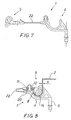
- Fig. 7 shows an embodiment of the invention, which consists in that the lower part 4 and the upper part 5 are connected to each other by a thin thread or ribbon-shaped connecting element 22. This ensures that an upper part 5 is always at hand during assembly for each lower part 4.
- the upper part 5 a rotating about the free end of the spreading spring 12, so that the flanging of the stringer 2 between the trough 10 Lower part and the curve 13 of the upper part is clamped.
- the dimensions of the compensating spring 20 are chosen so that there is always a sufficiently high clamping force even in the case of different stringer thicknesses s.
- the stringer 2 shown here has a smaller wall thickness in comparison with the stringer according to FIG. 1.
- the upper part 5 therefore appears under the influence of the compensating spring 20 pivoted through a larger angle than in Fig. 1.
- the band-shaped connecting element 22 has the curved shape shown in the assembled state.
Landscapes
- Engineering & Computer Science (AREA)
- General Engineering & Computer Science (AREA)
- Mechanical Engineering (AREA)
- Aviation & Aerospace Engineering (AREA)
- Connection Of Plates (AREA)
- Clamps And Clips (AREA)
Description
- Die Erfindung bezieht sich auf einen Halter zur Befestigung einer Isoliermatte zur Wärmedämmung an einer Flugzeugkabine, wobei der Halter an einem Stringer der Rumpfstruktur befestigt ist und einen mit der Isoliermatte verbindbaren Haltestift aufweist. Je Isoliermatte ist eine bestimmte Anzahl dieser Halter erforderlich.
- Aus der EP 320 377 A1 ist ein Halter zur Befestigung einer Isoliermatte zur Wärmedämmung einer Flugzeugkabine bekannt, wobei der Halter an einem Stringer der Rumpfstruktur befestigt ist, einen mit der Isoliermatte verbindbaren Haltestift aufweist und aus Kunststoff hergestellt werden kann. Zum Befestigen des Halters weist dieser eine Kralle und einen Spreizstift derart auf, daß die Kralle die Bördelung des Stringers umgreifen und der Spreizstift in eine im Steg des Stringers befindliche Bohrung eingesetzt werden kann. Die besagten Bohrungen stellen eine Schwachstelle im Oberflächenschutz des Stringers dar und verursachen einen erheblichen Aufwand in der Herstellung der Flugzeugstruktur.
- Die FR-A-1 362 078 zeigt einen anderen Halter zur Befestigung einer Isoliermatte zur Wärmedämmung einer Flugzeugkabine, wobei der Halter an einem Stringer der Rumpfstruktur befestigt ist, einen mit der Isoliermatte verbindbaren Haltestift aufweist und aus Kunststoff hergestellt werden kann. Zum Befestigen des Halters an einem Stringer weist dieser einen Fuß mit einem bogenförmigen Schlitz auf, der beim Ansetzen des Halters an den Stringer dessen Bördel aufnimmt. Zur Montage des Halters wird der Fuß mit dem Schlitz in Schräglage so an den Bördel des Stringers herangeführt, daß der Bördel bei einer Aufrichtung des Halters in den Schlitz eintreten kann. In aufrechter Lage des Halters wird dann ein Raststift in eine entsprechende Bohrung des Fußes eingedrückt, so daß der Fuß unter einer Vorspannung formschlüssig mit dem Stringer verbunden ist. Obwohl die Montage dieses Halters insofern vorteilhaft ist, als diese keine Bohrungen im Stringer erfordert, ist hierbei jedoch von Nachteil, daß er der der Halter aus mehreren einzelnen Teilen besteht, nämlich aus dem Fuß, dem Haltestift für die Isoliermatte und dem Raststift zur Sicherung des Fußes. Hierdurch gestaltet sich die Montage umständlich, wobei die Gefahr besteht, das wichtige Teile verlorengehen.
- Demgemäß liegt der Erfindung die Aufgabe zugrunde, einen gattungsgemäßen Halter so auszubilden, daß zu dessen Befestigung keine Bohrungen im Steg des Stringers erforderlich sind und der Halter keine verlierbaren Einzelteile umfaßt.
- Diese Aufgabe wird bei einem gattungsgemäßen Halter dadurch gelöst, daß dieser als auf den Stringer aufsetzbarer zweiteiliger Klipp ausgebildet ist, der ein Unterteil mit einer Mulde für den Stringer und ein als Schließteil ausgebildetes Oberteils umfaßt, wobei seitens des Unterteils ein Spreizstift und seitens des Oberteils eine auf dem Spreizstift verrastbare Aufnahme angeordnet ist, wobei ferner der Haltestift einstückig mit dem Unterteil verbunden ist und die Mulde aus einem bogenförmigen Bereich und einem ebenen Bereich besteht und das Oberteil aus einer Platte gebildet ist, die an ihrem in verrastetem Zustand dem Stringer zugewandten Ende in eine Rundung übergeht, die an der Innenseite der Bördelung anliegt, und an ihrem der Rundung abgewandten Ende eine angeformte Ausgleichsfeder zur Erzielung einer Klemmkraft zum Ausgleich unterschiedlicher Stringerdicken aufweist.
- Dabei ist insbesondere von Vorteil, daß die bisherige Bohrung im Steg des Stringers entfällt, so daß der Montageaufwand deutlich reduziert wird.
- Vorteilhafte Weiterbildungen der Erfindung sind in den Unteransprüchen angegeben.
- Die Erfindung ist anhand der Zeichnung beispielhaft dargestellt und nachfolgend näher erläutert. Es zeigen
- Fig. 1
- einen Kalter mit Ober- und Unterteil in montiertem Zustand,
- Fig. 2
- eine Ansicht des Unterteils,
- Fig. 3
- die Ansicht III des Unterteils nach Fig. 1,
- Fig. 4
- eine Ansicht des Oberteils,
- Fig. 5
- die Ansicht V des Oberteils nach Fig. 4,
- Fig. 6
- die Ansicht VI des Oberteils nach Fig. 4,
- Fig. 7
- einen Halter vor der Montage und
- Fig. 8
- einen montierten Halter.
- Figur 1 zeigt den Halter 1 in montiertem Zustand für eine nicht gezeigte Isoliermatte zur Wärmedämmung an einer Flugzeugkabine. Der aus thermoplastischem Kunststoff hergestellte Halter 1 ist an einem zur Rumpfstruktur gehörenden Stringer 2 durch Klemmung befestigt, wobei der Stringer 2 seinerseits mit der Außenhaut 3 des Flugzeugrumpfes verbunden ist. Zur Herstellung der Klemmung ist der Halter 1 als zweiteiliger Klipp ausgebildet, der aus einem Unterteil 4 und einem Oberteil 5 besteht, wobei der Haltestift 6 einstückig mit dem Unterteil 4 verbunden ist. Das Oberteil 5 ist als einrastbares Schließteil ausgebildet. Der Stringer 2 ist von Z-förmigem Querschnitt mit einem an der Außenhaut 3 befestigten Flansch 7, einem Steg 2a und einer kabinenseitigen Bördelung 8 von bogenförmigem Querschnitt. Zur Herstellung der Rastverbindung ist das Unterteil 4 mit einem Spreizstift 9 bekannter Art versehen, der beim Zusammenfügen von Unterteil 4 und Oberteil 5 in einer entsprechenden im Oberteil 5 angeordneten Aufnahme in Form einer Bohrung einrastet. Zur Befestigung einer Isoliermatte ist eine Vielzahl derartiger Halter erforderlich. Jede Isoliermatte weist Löcher auf, in denen sie auf die Haltestifte 6 aufgeschoben wird. Anschließend wird die Isoliermatte mittels nicht gezeigter elastischer Haltescheiben gesichert, die mit den Spitzen der Haltestifte 6 verrastbar sind.
- Die Figuren 2 und 3 zeigen das Unterteil 4 des Halters 1 mit dem Haltestift 6 und dem Spreizstift 9. Das Unterteil 4 weist auf seiner der Außenhaut 3 zugewandten Seite eine Mulde 10 auf, deren Form der Außenkontur der Bördelung 8 des Stringers 2 angepaßt ist und demzufolge aus einem bogenförmigen Bereich 10a und einem ebenen Bereich 10b besteht. Der Spreizstift 9 weist zwei ungleiche widerhakenartige Spreizfedern 11 und 12 auf. Die Spreizfeder 11 ist von geringerer Wandstärke als die Feder 12 und reicht näher an den Fuß des Spreizstiftes 9 heran als diese. Das Unterteil 4 ist so ausgebildet, daß eine mit E bezeichnete Hauptebene bei sauber montiertem Halter 1 parallel zur hier nicht gezeigten Rumpfaußenhaut verläuft. Da der Haltestift 6 in montiertem Zustand annähernd senkrecht auf der Außenhaut stehen soll, steht dieser auch senkrecht auf der Hauptebene E.
- Die Figuren 4 bis 6 zeigen das Oberteil 5 des Halters 1 mit einer Rundung 13, und einer Platte 14 mit einer Aufnahme 15. Dabei ergibt sich die Rundung 13 als Außenfläche eines Hohlzylinders 16, woran die Platte 14 annähernd tangential angeformt ist, wobei die Breite B der Platte 14 mit der Länge des Hohlzylinders 16 übereinstimmt. In Fig. 4 oberhalb des Hohlzylinders 16 sind zwei Klemmnasen 17 und 18 angeordnet, die jeweils mit der Rundung 13 eine ebene Fläche 17' bzw. 18' bilden, die tangential in die Rundung 13 übergeht. Am der Rundung 13 abgewandten Rand der Platte 14 ist eine Ausgleichsfeder 20 so angeformt, daß diese schräg nach unten zur Rundung 13 hin zeigt. Diese als Blattfeder ausgebildete Ausgleichsfeder 20 erstreckt sich über die gesamte Breite der Platte 14 und schließt mit dieser einen Winkel von ca. 30° ein. Auf der Oberseite der Platte 14 ist in der Umgebung der Aufnahme 15 eine Vertiefung 21 von rechteckigem Umriß angeordnet.
- Fig. 7 zeigt eine Ausgestaltung der Erfindung, die darin besteht, daß das Unterteil 4 und das Oberteil 5 durch ein dünnes faden- oder bandförmiges Verbindungselement 22 miteinander verbunden sind. Hierdurch wird erreicht, daß bei der Montage zu jedem Unterteil 4 immer ein Oberteil 5 zur Hand ist.
- Fig. 8 zeigt den Halter 1 nochmals in montiertem Zustand mit dem Stringer 2, dem Unterteil 4, dem Oberteil 5 und dem Haltestift 6. Das Unterteil 4 ist an den Stringer 2 angesetzt und das Oberteil 5 ist mit dem Unterteil 4 durch den Spreizstift 9 verbunden. Dabei liegt die Rundung 13 von innen an der Bördelung 8 an. Das freie Ende der Spreizfeder 12 stützt sich auf dem Grund der Vertiefung 21 ab und bewirkt so den Zusammenhalt von Unterteil 4 und Oberteil 5. Demgegenüber befindet sich das freie Ende der Spreizfeder 11 deutlich innerhalb der Aufnahme 15 und liegt somit an der Innenfläche der Aufnahme 15 unter einer Vorspannung an. Hierdurch wird sichergestellt, daß der Spreizstift 9 innerhalb der Aufnahme 15 in Richtung quer zum Stringer 2 einen spielfreien Sitz erhält. In montiertem Zustand ist, wie das Bild zeigt, die Ausgleichsfeder 20 angespannt und übt eine Druckkraft auf das Unterteil 4 aus. Hierdurch wirkt auf das Oberteil 5 ein um das freie Ende der Spreizfeder 12 drehendes Moment, so daß die Bördelung des Stringers 2 zwischen der Mulde 10 des Unterteils und der Rundung 13 des Oberteils eingeklemmt wird. Die Abmessungen der Ausgleichsfeder 20 sind so gewählt, daß sich auch im Falle unterschiedlicher Stringerdicken s stets eine hinreichend hohe Klemmkraft ergibt. Der hier gezeigte Stringer 2 ist im Vergleich mit dem Stringer nach Fig. 1 von geringerer Wandstärke. Das Oberteil 5 erscheint daher unter dem Einfluß der Ausgleichsfeder 20 um einen größeren Winkel geschwenkt als in Fig. 1. Das bandförmige Verbindungselement 22 weist in montiertem Zustand die gezeigte gebogene Form auf.
Claims (6)
- Halter (1) zur Befestigung einer Isoliermatte zur Wärmedämmung einer Flugzeugkabine, wobei der Halter an einem Stringer (2) der Rumpfstruktur befestigt ist, wobei der Stringer einen z-förmigen Querschnitt mit einem strukturseitigen Flansch (7) und einer kabinenseitigen Bördelung (8) von bogenförmigem Querschnitt zeigt und der Halter einen mit der Isoliermatte verbindbaren Haltestift (6) aufweist,
dadurch gekennzeichnet, daß der Halter als auf den Stringer (2) aufsetzbarer zweiteiliger Klipp ausgebildet ist, der ein Unterteil mit einer Mulde (10) für den Stringer (2) und ein als Schließteil ausgebildetes Oberteils (5) umfaßt, wobei seitens des Unterteils (4) ein Spreizstift (9) und seitens des Oberteils (5) eine auf dem Spreizstift (9) verrastbare Aufnahme (15) angeordnet ist, wobei ferner der Haltestift (6) einstückig mit dem Unterteil (4) verbunden ist und die Mulde (10) aus einem bogenförmigen Bereich (10a) und einem ebenen Bereich (10b) besteht und das Oberteil (5) aus einer Platte (14) gebildet ist, die an ihrem in verrastetem Zustand dem Stringer (2) zugewandten Ende in eine Rundung (13) übergeht, die an der Innenseite der Bördelung (8) anliegt, und an ihrem der Rundung (13) abgewandten Ende eine angeformte Ausgleichsfeder (20) zur Erzielung einer Klemmkraft zum Ausgleich unterschiedlicher Stringerdicken aufweist. - Halter nach Anspruch 1,
dadurch gekennzeichnet, daß der Spreizstift (9) zwei widerhakenartige Spreizfedern (11) und (12) von unterschiedlicher Länge aufweist. - Kalter nach Anspruch 1 oder 2,
dadurch gekennzeichnet, daß das freie Ende der längeren Spreizfeder (11) in montiertem Zustand innerhalb der Aufnahme (15) liegt. - Halter nach einem der Ansprüche 1 bis 3,
dadurch gekennzeichnet, daß das freie Ende der kürzeren Spreizfeder (12) in montiertem Zustand außerhalb der Aufnahme (15) liegt. - Halter nach einem der Ansprüche 1 bis 4,
dadurch gekennzeichnet, daß auf der Oberseite der Platte (14) in der Umgebung der Aufnahme (15) eine Vertiefung (21) von rechteckigem Umriß angeordnet ist. - Halter nach einem der Ansprüche 1 bis 5,
dadurch gekennzeichnet, daß das Unterteil (4) und das Oberteil (5) durch ein dünnes faden- oder bandförmiges Verbindungselement (22) miteinander verbunden sind.
Applications Claiming Priority (2)
| Application Number | Priority Date | Filing Date | Title |
|---|---|---|---|
| DE4208494 | 1992-03-17 | ||
| DE4208494A DE4208494C1 (de) | 1992-03-17 | 1992-03-17 | Halter für eine Isoliermatte |
Publications (2)
| Publication Number | Publication Date |
|---|---|
| EP0561107A1 EP0561107A1 (de) | 1993-09-22 |
| EP0561107B1 true EP0561107B1 (de) | 1995-11-02 |
Family
ID=6454264
Family Applications (1)
| Application Number | Title | Priority Date | Filing Date |
|---|---|---|---|
| EP93100108A Expired - Lifetime EP0561107B1 (de) | 1992-03-17 | 1993-01-07 | Halterung für eine Isoliermatte |
Country Status (6)
| Country | Link |
|---|---|
| US (1) | US5263665A (de) |
| EP (1) | EP0561107B1 (de) |
| JP (1) | JPH068885A (de) |
| AT (1) | ATE129682T1 (de) |
| DE (1) | DE4208494C1 (de) |
| ES (1) | ES2080530T3 (de) |
Families Citing this family (21)
| Publication number | Priority date | Publication date | Assignee | Title |
|---|---|---|---|---|
| RU2196074C2 (ru) * | 1999-03-12 | 2003-01-10 | Открытое акционерное общество Авиационный научно-технический комплекс им. А.Н.Туполева | Способ крепления теплозвукоизоляции к каркасу летательного аппарата |
| US6505794B2 (en) | 2001-01-24 | 2003-01-14 | The Boeing Company | Large thermal protection system panel |
| FR2856027B1 (fr) * | 2003-06-12 | 2006-02-10 | Plastic Omnium Cie | Piece en matiere plastique pour vehicule automobile et ensemble de deux pieces de vehicule automobile |
| DE10331268B4 (de) * | 2003-07-10 | 2009-10-08 | Iwg Isolier Wendt Gmbh | Anordnung für die thermische und/oder akustische Isolierung einer Anlage |
| DE102004025375B4 (de) | 2004-05-24 | 2010-01-28 | Airbus Deutschland Gmbh | Fensterrahmen für Flugzeuge |
| JP2006298131A (ja) * | 2005-04-20 | 2006-11-02 | Piolax Inc | 自動車の内装部品と車体パネルとの連結構造 |
| DE102006039292B4 (de) * | 2006-08-22 | 2010-07-22 | Airbus Deutschland Gmbh | Rahmenelement, Flugzeugklimatisierungssystem sowie Verfahren zur Montage eines Rahmenelements in einem Flugzeug |
| EP2054296B1 (de) * | 2006-08-22 | 2010-12-01 | Airbus Deutschland GmbH | Rahmenelement, montagesystem für flugzeugkomponenten und verfahren für den einbau einer komponente in ein flugzeug |
| FR2933376B1 (fr) * | 2008-07-07 | 2011-12-09 | Airbus France | Dispositif de fixation de matelas isolants et procede de pose de matelas isolants dans un fuselage d'aeronef |
| DE102008043448B4 (de) | 2008-11-04 | 2017-05-18 | Airbus Operations Gmbh | Halteranordnung eines Luft- oder Raumfahrzeugs und Luft-oder Raumfahrzeug |
| US8561266B2 (en) * | 2008-11-04 | 2013-10-22 | Airbus Operations Gmbh | Holder arrangement for an aircraft or a spacecraft and an aircraft or a spacecraft |
| FR2961486B1 (fr) | 2010-06-22 | 2013-03-22 | Airbus Operations Sas | Dispositif pour le maintien d'un matelas isolant et la fixation de systemes |
| FR2961489B1 (fr) * | 2010-06-22 | 2013-06-14 | Airbus Operations Sas | Dispositif pour le maintien d'un matelas isolant et la fixation de systemes en deux pieces |
| US9878772B2 (en) * | 2012-01-10 | 2018-01-30 | Gulfstream Aerospace Corporation | Mounting assembly and method for mounting a sound-deadening body to a fuselage of an aircraft |
| DE102012023767A1 (de) * | 2012-12-05 | 2014-06-05 | GM Global Technology Operations LLC (n. d. Ges. d. Staates Delaware) | Befestigungselement für ein Kraftfahrzeug |
| US10059427B2 (en) | 2014-03-25 | 2018-08-28 | Gulfstream Aerospace Corporation | Over-frame blanket assemblies and methods of installation in fuselage assemblies |
| US9821747B2 (en) | 2014-10-09 | 2017-11-21 | Newfrey Llc | Tethered fastener and related methods |
| DE102017102609A1 (de) | 2016-02-09 | 2017-08-10 | Comprisetec Gmbh | Verbindung von Bauteilen mittels Oberflächenstrukturen |
| CN105773481B (zh) * | 2016-05-06 | 2018-03-13 | 江西昌河航空工业有限公司 | 一种飞机长桁压紧器 |
| EP3708483B1 (de) * | 2019-03-14 | 2021-09-15 | SFS Intec Holding AG | Haltevorrichtung für wandmodule |
| DE102024101769A1 (de) * | 2024-01-22 | 2025-07-24 | Elbe Flugzeugwerke Gmbh | Klemmhalter zum Befestigen von Bauteilen an Strukturkomponenten eines Fahrzeugs |
Family Cites Families (5)
| Publication number | Priority date | Publication date | Assignee | Title |
|---|---|---|---|---|
| FR1362078A (fr) * | 1963-04-19 | 1964-05-29 | Dispositif de fixation combinée de matelas d'insonorisation et de conducteurs électriques sur le fuselage des aéronefs | |
| US4739955A (en) * | 1986-09-30 | 1988-04-26 | The Boeing Company | Aircraft cabin panel and insulation retainer with integrated use as a spacer-isolator |
| JPH0416007Y2 (de) * | 1987-09-21 | 1992-04-10 | ||
| FR2624219B1 (fr) * | 1987-12-08 | 1990-03-30 | Aerospatiale | Dispositif de fixation d'un objet sur une structure rigide |
| US5031268A (en) * | 1990-04-11 | 1991-07-16 | E. I. Du Pont De Nemours And Company | Corner guard assembly |
-
1992
- 1992-03-17 DE DE4208494A patent/DE4208494C1/de not_active Expired - Fee Related
-
1993
- 1993-01-07 AT AT93100108T patent/ATE129682T1/de not_active IP Right Cessation
- 1993-01-07 EP EP93100108A patent/EP0561107B1/de not_active Expired - Lifetime
- 1993-01-07 ES ES93100108T patent/ES2080530T3/es not_active Expired - Lifetime
- 1993-01-29 JP JP5014156A patent/JPH068885A/ja not_active Withdrawn
- 1993-03-17 US US08/032,126 patent/US5263665A/en not_active Expired - Lifetime
Also Published As
| Publication number | Publication date |
|---|---|
| ES2080530T3 (es) | 1996-02-01 |
| EP0561107A1 (de) | 1993-09-22 |
| DE4208494C1 (de) | 1993-09-30 |
| ATE129682T1 (de) | 1995-11-15 |
| US5263665A (en) | 1993-11-23 |
| JPH068885A (ja) | 1994-01-18 |
Similar Documents
| Publication | Publication Date | Title |
|---|---|---|
| DE4208494C1 (de) | Halter für eine Isoliermatte | |
| DE29519375U1 (de) | Kunststoff-Befestigungselement, insbesondere für eine Fahrzeugverkleidung | |
| CH373652A (de) | An der Windschutzscheibe eines Automobils angeordneter Rückblickspiegel | |
| DE4332286C2 (de) | Stoßfänger-Befestigungsvorrichtung | |
| DE102004025375B4 (de) | Fensterrahmen für Flugzeuge | |
| DE10118111B4 (de) | Gurteinfügungsteil | |
| DE3903124C2 (de) | Grundplatte aus Kunststoff | |
| DE4208493C2 (de) | Halterung für eine Isoliermatte | |
| DE3881476T2 (de) | In Schulterhöhe einstellbarer Verankerungsmechanismus. | |
| DE102009035874A1 (de) | Vorrichtung zur Verbindung zweier Bauteile miteinander | |
| DE3602198C1 (en) | Holding device for motor-vehicle window panes which can be bonded in place | |
| DE102015114230B4 (de) | Anbindungssystem zur Befestigung eines Bauteil an einer Fahrzeugkarosserie | |
| WO2001031230A1 (de) | Spannschiene für kettentriebe | |
| DE4142598C1 (en) | Glove pocket lid hinge - has fastener plate allocated to body-fixed tap with straps allowing plate to move in two dimensions relative to support | |
| DE29921416U1 (de) | Gassack-Modulgehäuse | |
| EP2300677B1 (de) | Scharniertopf für möbelscharniere | |
| DE102006002195B4 (de) | Klammer zur Befestigung eines Bauteils | |
| EP1366942B1 (de) | Verdeckstoffbefestigung für ein Cabriolet | |
| DE102018107083A1 (de) | Befestigungseinrichtung und Verfahren zur Befestigung eines Anbauteils an einem Tragteil, Bauteilsystem und Kraftfahrzeug | |
| DE3721783A1 (de) | Anordnung zur loesbaren befestigung einer verkleidung an einem tragenden bauteil | |
| WO2000055007A1 (de) | Einrichtung zum befestigen einer zusatzmatte in einem kraftfahrzeug | |
| DE69800004T2 (de) | Befestigungsvorrichtung für einen Aussenrückblickspiegel auf einem Kraftfahrzeug | |
| DE2259860A1 (de) | Lampenfassung | |
| DE8002883U1 (de) | Kunststoff-Clip zur Befestigung von Verkleidungen in Kraftfahrzeugen o.dgl | |
| EP0791527B1 (de) | Verbindung von flächigen Kunststoffteilen |
Legal Events
| Date | Code | Title | Description |
|---|---|---|---|
| PUAI | Public reference made under article 153(3) epc to a published international application that has entered the european phase |
Free format text: ORIGINAL CODE: 0009012 |
|
| AK | Designated contracting states |
Kind code of ref document: A1 Designated state(s): AT BE CH DK ES FR GB GR IT LI LU NL PT SE |
|
| 17P | Request for examination filed |
Effective date: 19930901 |
|
| 17Q | First examination report despatched |
Effective date: 19940608 |
|
| RAP1 | Party data changed (applicant data changed or rights of an application transferred) |
Owner name: DAIMLER-BENZ AEROSPACE AIRBUS GESELLSCHAFT MIT BES |
|
| GRAA | (expected) grant |
Free format text: ORIGINAL CODE: 0009210 |
|
| AK | Designated contracting states |
Kind code of ref document: B1 Designated state(s): AT BE CH DK ES FR GB GR IT LI LU NL PT SE |
|
| PG25 | Lapsed in a contracting state [announced via postgrant information from national office to epo] |
Ref country code: GR Free format text: LAPSE BECAUSE OF FAILURE TO SUBMIT A TRANSLATION OF THE DESCRIPTION OR TO PAY THE FEE WITHIN THE PRESCRIBED TIME-LIMIT Effective date: 19951102 Ref country code: DK Effective date: 19951102 Ref country code: BE Effective date: 19951102 |
|
| REF | Corresponds to: |
Ref document number: 129682 Country of ref document: AT Date of ref document: 19951115 Kind code of ref document: T |
|
| PG25 | Lapsed in a contracting state [announced via postgrant information from national office to epo] |
Ref country code: AT Effective date: 19960107 |
|
| ITF | It: translation for a ep patent filed | ||
| PG25 | Lapsed in a contracting state [announced via postgrant information from national office to epo] |
Ref country code: LU Free format text: LAPSE BECAUSE OF NON-PAYMENT OF DUE FEES Effective date: 19960131 Ref country code: LI Effective date: 19960131 Ref country code: CH Effective date: 19960131 |
|
| REG | Reference to a national code |
Ref country code: ES Ref legal event code: FG2A Ref document number: 2080530 Country of ref document: ES Kind code of ref document: T3 |
|
| PG25 | Lapsed in a contracting state [announced via postgrant information from national office to epo] |
Ref country code: PT Effective date: 19960202 |
|
| GBT | Gb: translation of ep patent filed (gb section 77(6)(a)/1977) |
Effective date: 19960106 |
|
| NLT2 | Nl: modifications (of names), taken from the european patent patent bulletin |
Owner name: DAIMLER-BENZ AEROSPACE AIRBUS GESELLSCHAFT MIT BES |
|
| ET | Fr: translation filed | ||
| PLBE | No opposition filed within time limit |
Free format text: ORIGINAL CODE: 0009261 |
|
| STAA | Information on the status of an ep patent application or granted ep patent |
Free format text: STATUS: NO OPPOSITION FILED WITHIN TIME LIMIT |
|
| REG | Reference to a national code |
Ref country code: CH Ref legal event code: PL |
|
| 26N | No opposition filed | ||
| REG | Reference to a national code |
Ref country code: FR Ref legal event code: CD |
|
| REG | Reference to a national code |
Ref country code: GB Ref legal event code: IF02 |
|
| PGFP | Annual fee paid to national office [announced via postgrant information from national office to epo] |
Ref country code: SE Payment date: 20091223 Year of fee payment: 18 |
|
| PGFP | Annual fee paid to national office [announced via postgrant information from national office to epo] |
Ref country code: ES Payment date: 20100125 Year of fee payment: 18 |
|
| PGFP | Annual fee paid to national office [announced via postgrant information from national office to epo] |
Ref country code: IT Payment date: 20100127 Year of fee payment: 18 Ref country code: FR Payment date: 20100223 Year of fee payment: 18 |
|
| PGFP | Annual fee paid to national office [announced via postgrant information from national office to epo] |
Ref country code: GB Payment date: 20100121 Year of fee payment: 18 |
|
| PGFP | Annual fee paid to national office [announced via postgrant information from national office to epo] |
Ref country code: NL Payment date: 20100118 Year of fee payment: 18 |
|
| REG | Reference to a national code |
Ref country code: NL Ref legal event code: V1 Effective date: 20110801 |
|
| REG | Reference to a national code |
Ref country code: SE Ref legal event code: EUG |
|
| GBPC | Gb: european patent ceased through non-payment of renewal fee |
Effective date: 20110107 |
|
| REG | Reference to a national code |
Ref country code: FR Ref legal event code: ST Effective date: 20110930 |
|
| PG25 | Lapsed in a contracting state [announced via postgrant information from national office to epo] |
Ref country code: FR Free format text: LAPSE BECAUSE OF NON-PAYMENT OF DUE FEES Effective date: 20110131 |
|
| PG25 | Lapsed in a contracting state [announced via postgrant information from national office to epo] |
Ref country code: GB Free format text: LAPSE BECAUSE OF NON-PAYMENT OF DUE FEES Effective date: 20110107 |
|
| PG25 | Lapsed in a contracting state [announced via postgrant information from national office to epo] |
Ref country code: IT Free format text: LAPSE BECAUSE OF NON-PAYMENT OF DUE FEES Effective date: 20110107 Ref country code: NL Free format text: LAPSE BECAUSE OF NON-PAYMENT OF DUE FEES Effective date: 20110801 |
|
| REG | Reference to a national code |
Ref country code: ES Ref legal event code: FD2A Effective date: 20120220 |
|
| PG25 | Lapsed in a contracting state [announced via postgrant information from national office to epo] |
Ref country code: ES Free format text: LAPSE BECAUSE OF NON-PAYMENT OF DUE FEES Effective date: 20110108 |
|
| PG25 | Lapsed in a contracting state [announced via postgrant information from national office to epo] |
Ref country code: SE Free format text: LAPSE BECAUSE OF NON-PAYMENT OF DUE FEES Effective date: 20110108 |