EP0561107B1 - Support pour une couche isolante - Google Patents
Support pour une couche isolante Download PDFInfo
- Publication number
- EP0561107B1 EP0561107B1 EP93100108A EP93100108A EP0561107B1 EP 0561107 B1 EP0561107 B1 EP 0561107B1 EP 93100108 A EP93100108 A EP 93100108A EP 93100108 A EP93100108 A EP 93100108A EP 0561107 B1 EP0561107 B1 EP 0561107B1
- Authority
- EP
- European Patent Office
- Prior art keywords
- stringer
- holder
- pin
- expanding
- insulating mat
- Prior art date
- Legal status (The legal status is an assumption and is not a legal conclusion. Google has not performed a legal analysis and makes no representation as to the accuracy of the status listed.)
- Expired - Lifetime
Links
- 238000009413 insulation Methods 0.000 claims abstract description 6
- 238000007688 edging Methods 0.000 claims 2
- 230000014759 maintenance of location Effects 0.000 claims 2
- 229920001169 thermoplastic Polymers 0.000 abstract description 2
- 239000004416 thermosoftening plastic Substances 0.000 abstract description 2
- 238000009434 installation Methods 0.000 abstract 1
- 229920002994 synthetic fiber Polymers 0.000 abstract 1
- 210000000078 claw Anatomy 0.000 description 2
- 239000004033 plastic Substances 0.000 description 2
- 238000011161 development Methods 0.000 description 1
- 230000018109 developmental process Effects 0.000 description 1
- 238000004519 manufacturing process Methods 0.000 description 1
- 230000036316 preload Effects 0.000 description 1
Images

Classifications
-
- B—PERFORMING OPERATIONS; TRANSPORTING
- B64—AIRCRAFT; AVIATION; COSMONAUTICS
- B64C—AEROPLANES; HELICOPTERS
- B64C1/00—Fuselages; Constructional features common to fuselages, wings, stabilising surfaces or the like
- B64C1/40—Sound or heat insulation, e.g. using insulation blankets
-
- B—PERFORMING OPERATIONS; TRANSPORTING
- B64—AIRCRAFT; AVIATION; COSMONAUTICS
- B64C—AEROPLANES; HELICOPTERS
- B64C1/00—Fuselages; Constructional features common to fuselages, wings, stabilising surfaces or the like
- B64C1/40—Sound or heat insulation, e.g. using insulation blankets
- B64C1/403—Arrangement of fasteners specially adapted therefor, e.g. of clips
-
- F—MECHANICAL ENGINEERING; LIGHTING; HEATING; WEAPONS; BLASTING
- F16—ENGINEERING ELEMENTS AND UNITS; GENERAL MEASURES FOR PRODUCING AND MAINTAINING EFFECTIVE FUNCTIONING OF MACHINES OR INSTALLATIONS; THERMAL INSULATION IN GENERAL
- F16B—DEVICES FOR FASTENING OR SECURING CONSTRUCTIONAL ELEMENTS OR MACHINE PARTS TOGETHER, e.g. NAILS, BOLTS, CIRCLIPS, CLAMPS, CLIPS OR WEDGES; JOINTS OR JOINTING
- F16B5/00—Joining sheets or plates, e.g. panels, to one another or to strips or bars parallel to them
- F16B5/06—Joining sheets or plates, e.g. panels, to one another or to strips or bars parallel to them by means of clamps or clips
- F16B5/0607—Joining sheets or plates, e.g. panels, to one another or to strips or bars parallel to them by means of clamps or clips joining sheets or plates to each other
- F16B5/0621—Joining sheets or plates, e.g. panels, to one another or to strips or bars parallel to them by means of clamps or clips joining sheets or plates to each other in parallel relationship
- F16B5/0642—Joining sheets or plates, e.g. panels, to one another or to strips or bars parallel to them by means of clamps or clips joining sheets or plates to each other in parallel relationship the plates being arranged one on top of the other and in full close contact with each other
-
- F—MECHANICAL ENGINEERING; LIGHTING; HEATING; WEAPONS; BLASTING
- F16—ENGINEERING ELEMENTS AND UNITS; GENERAL MEASURES FOR PRODUCING AND MAINTAINING EFFECTIVE FUNCTIONING OF MACHINES OR INSTALLATIONS; THERMAL INSULATION IN GENERAL
- F16B—DEVICES FOR FASTENING OR SECURING CONSTRUCTIONAL ELEMENTS OR MACHINE PARTS TOGETHER, e.g. NAILS, BOLTS, CIRCLIPS, CLAMPS, CLIPS OR WEDGES; JOINTS OR JOINTING
- F16B5/00—Joining sheets or plates, e.g. panels, to one another or to strips or bars parallel to them
- F16B5/06—Joining sheets or plates, e.g. panels, to one another or to strips or bars parallel to them by means of clamps or clips
- F16B5/0607—Joining sheets or plates, e.g. panels, to one another or to strips or bars parallel to them by means of clamps or clips joining sheets or plates to each other
- F16B5/0621—Joining sheets or plates, e.g. panels, to one another or to strips or bars parallel to them by means of clamps or clips joining sheets or plates to each other in parallel relationship
- F16B5/0664—Joining sheets or plates, e.g. panels, to one another or to strips or bars parallel to them by means of clamps or clips joining sheets or plates to each other in parallel relationship at least one of the sheets or plates having integrally formed or integrally connected snap-in-features
-
- Y—GENERAL TAGGING OF NEW TECHNOLOGICAL DEVELOPMENTS; GENERAL TAGGING OF CROSS-SECTIONAL TECHNOLOGIES SPANNING OVER SEVERAL SECTIONS OF THE IPC; TECHNICAL SUBJECTS COVERED BY FORMER USPC CROSS-REFERENCE ART COLLECTIONS [XRACs] AND DIGESTS
- Y10—TECHNICAL SUBJECTS COVERED BY FORMER USPC
- Y10T—TECHNICAL SUBJECTS COVERED BY FORMER US CLASSIFICATION
- Y10T24/00—Buckles, buttons, clasps, etc.
- Y10T24/30—Trim molding fastener
- Y10T24/309—Plastic type
Definitions
- the invention relates to a holder for fastening an insulating mat for thermal insulation to an aircraft cabin, the holder being fastened to a stringer of the fuselage structure and having a holding pin which can be connected to the insulating mat. A certain number of these holders is required for each insulating mat.
- EP 320 377 A1 discloses a holder for fastening an insulating mat for thermal insulation of an aircraft cabin, the holder being fastened to a stringer of the fuselage structure, having a holding pin which can be connected to the insulating mat, and which can be produced from plastic.
- the holder has a claw and an expanding pin such that the claw engages around the flanging of the stringer and the expanding pin can be inserted into a bore located in the web of the stringer. Said bores represent a weak point in the surface protection of the stringer and cause considerable effort in the manufacture of the aircraft structure.
- FR-A-1 362 078 shows another holder for attaching an insulating mat for the thermal insulation of an aircraft cabin, the holder being fastened to a stringer of the fuselage structure, having a holding pin which can be connected to the insulating mat and which can be produced from plastic.
- the stringer has a foot with an arcuate slot, which receives the flange when the holder is attached to the stringer.
- the foot with the slot is inclined to the flange of the stringer so that the flange can enter the slot when the holder is erected.
- a locking pin is then pressed into a corresponding hole in the foot, so that the foot is positively connected to the stringer under a prestress.
- the assembly of this holder is advantageous insofar as it does not require any holes in the stringer, it is disadvantageous here that the holder consists of several individual parts, namely the foot, the holding pin for the insulating mat and the locking pin for securing the Foot. This makes assembly difficult, with the risk of important parts being lost.
- the invention has for its object to provide a generic holder so that no holes in the web of the stringer are required for its attachment and the holder does not include any loose parts.
- a generic holder in that it is designed as a two-part clip which can be placed on the stringer and which comprises a lower part with a trough for the stringer and an upper part designed as a closing part, with an expansion pin on the part and an upper part on the part is arranged on the spreader pin, the holding pin is also integrally connected to the lower part and the trough consists of an arcuate region and a flat region and the upper part is formed from a plate which in its latched state facing the stringer in a curve merges, which rests on the inside of the flange, and has a molded compensating spring on its end facing away from the curve to achieve a clamping force to compensate for different stringer thicknesses.
- Figure 1 shows the holder 1 in the assembled state for an insulating mat, not shown, for thermal insulation in an aircraft cabin.
- the holder 1 made of thermoplastic is attached to a stringer 2 belonging to the fuselage structure by clamping, the stringer 2 in turn being connected to the outer skin 3 of the fuselage.
- the holder 1 is designed as a two-part clip, which consists of a lower part 4 and an upper part 5, the retaining pin 6 being connected in one piece to the lower part 4.
- the upper part 5 is designed as a snap-in closing part.
- the stringer 2 is of Z-shaped cross section with a flange 7 fastened to the outer skin 3, a web 2a and a flare 8 on the cabin side of an arched cross section.
- the lower part 4 is provided with an expansion pin 9 of known type, which engages when the lower part 4 and upper part 5 are joined in a corresponding receptacle arranged in the upper part 5 in the form of a bore.
- a large number of such holders are required for fastening an insulating mat.
- Each insulating mat has holes in which it is pushed onto the holding pins 6.
- the insulating mat is then secured by means of elastic holding disks, not shown, which can be locked with the tips of the holding pins 6.
- Figures 2 and 3 show the lower part 4 of the holder 1 with the holding pin 6 and the expansion pin 9.
- the lower part 4 has on its side facing the outer skin 3 a trough 10, the shape of the outer contour of the flange 8 of the stringer 2 is adapted and consequently consists of an arcuate region 10a and a flat region 10b.
- the expansion pin 9 has two unequal barb-like expansion springs 11 and 12.
- the expansion spring 11 is of smaller wall thickness than the spring 12 and extends closer to the foot of the expansion pin 9 than this.
- the lower part 4 is designed such that a main plane labeled E runs parallel to the outer skin of the fuselage, not shown, when the holder 1 is properly installed. Since the retaining pin 6 is to be approximately perpendicular to the outer skin in the assembled state, it is also perpendicular to the main plane E.
- Figures 4 to 6 show the upper part 5 of the holder 1 with a curve 13, and a plate 14 with a receptacle 15.
- the curve 13 is the outer surface of a hollow cylinder 16, on which the plate 14 is formed approximately tangentially, the width B of the plate 14 corresponds to the length of the hollow cylinder 16.
- two clamping lugs 17 and 18 are arranged, each with the rounding 13 a flat surface 17 'and 18' form, which merges tangentially into the curve 13.
- a compensating spring 20 is formed in such a way that it points obliquely downward towards the rounding 13.
- This compensating spring 20 designed as a leaf spring, extends over the entire width of the plate 14 and forms an angle of approximately 30 ° with it.
- a recess 21 of rectangular outline is arranged on the top of the plate 14 in the vicinity of the receptacle 15.
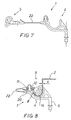
- Fig. 7 shows an embodiment of the invention, which consists in that the lower part 4 and the upper part 5 are connected to each other by a thin thread or ribbon-shaped connecting element 22. This ensures that an upper part 5 is always at hand during assembly for each lower part 4.
- the upper part 5 a rotating about the free end of the spreading spring 12, so that the flanging of the stringer 2 between the trough 10 Lower part and the curve 13 of the upper part is clamped.
- the dimensions of the compensating spring 20 are chosen so that there is always a sufficiently high clamping force even in the case of different stringer thicknesses s.
- the stringer 2 shown here has a smaller wall thickness in comparison with the stringer according to FIG. 1.
- the upper part 5 therefore appears under the influence of the compensating spring 20 pivoted through a larger angle than in Fig. 1.
- the band-shaped connecting element 22 has the curved shape shown in the assembled state.
Landscapes
- Engineering & Computer Science (AREA)
- General Engineering & Computer Science (AREA)
- Mechanical Engineering (AREA)
- Aviation & Aerospace Engineering (AREA)
- Connection Of Plates (AREA)
- Clamps And Clips (AREA)
Claims (6)
- Support (1) destiné à la fixation d'un matelas isolant destiné à isoler une cabine d'un avion contre les effets de la chaleur, ledit support étant fixé sur un raidisseur (2) du fuselage, ce raidisseur présentant une section transversale en forme de Z pourvue d'une bride (7) côté structure et d'une collerette (8) de section transversale en forme d'arc de cercle côté cabine, alors que le support présente une cheville d'arrêt (6) pouvant être reliée au matelas isolant, caractérisé en ce que le support est conçu comme une pince en deux parties pouvant être montée sur le raidisseur (2), cette pince comprenant une partie inférieure pourvue d'une cavité (10) pour le raidisseur (2) et une partie supérieure (5) conçue comme un élément de fermeture, une cheville à écartement (9) étant disposée à côté de la partie inférieure (4) et un logement (15) encliquetable sur la cheville à écartement (9) étant disposé à côté de la partie supérieure (5), la cheville d'arrêt (6) étant en outre solidaire de la partie inférieure (4) et la cavité (10) se composant d'une zone (10a) en forme d'arc de cercle et d'une zone (10b) plate, alors que la partie supérieure (5) est composée d'une plaque (14) dont l'extrémité tournée vers le raidisseur s'engrène, à l'état verrouillé, dans une courbure (13), laquelle repose sur la face interne de la collerette (8), et dont l'extrémité opposée à la courbure (13) présente un ressort compensateur (20) destiné à fournir une force de serrage dont le but est de compenser les différences d'épaisseur du raidisseur.
- Support selon la revendication 1, caractérisé en ce que la cheville à écartement (9) présente deux ressorts d'écartement (11) et (12) de type barbelé de longueur différente.
- Support selon l'une ou l'autre des revendications 1 et 2, caractérisé en ce que l'extrémité libre du ressort d'écartement (11) le plus long repose à l'état monté à l'intérieur du logement (15).
- Support selon l'une ou l'autre des revendications 1 à 3, caractérisé en ce que l'extrémité libre du ressort d'écartement (12) le plus court repose à l'état monté à l'extérieur du logement (15).
- Support selon l'une ou l'autre des revendications 1 à 4, caractérisé en ce que sur la face supérieure de la plaque (14) autour du logement (15) est prévu un évidement (21) de profil rectangulaire.
- Support selon l'une ou l'autre des revendications 1 à 5, caractérisé en ce que la partie inférieure (4) et la partie supérieure (5) sont reliées l'une à l'autre par un fin élément de liaison (22) en forme de fil ou de ruban.
Applications Claiming Priority (2)
| Application Number | Priority Date | Filing Date | Title |
|---|---|---|---|
| DE4208494A DE4208494C1 (de) | 1992-03-17 | 1992-03-17 | Halter für eine Isoliermatte |
| DE4208494 | 1992-03-17 |
Publications (2)
| Publication Number | Publication Date |
|---|---|
| EP0561107A1 EP0561107A1 (fr) | 1993-09-22 |
| EP0561107B1 true EP0561107B1 (fr) | 1995-11-02 |
Family
ID=6454264
Family Applications (1)
| Application Number | Title | Priority Date | Filing Date |
|---|---|---|---|
| EP93100108A Expired - Lifetime EP0561107B1 (fr) | 1992-03-17 | 1993-01-07 | Support pour une couche isolante |
Country Status (6)
| Country | Link |
|---|---|
| US (1) | US5263665A (fr) |
| EP (1) | EP0561107B1 (fr) |
| JP (1) | JPH068885A (fr) |
| AT (1) | ATE129682T1 (fr) |
| DE (1) | DE4208494C1 (fr) |
| ES (1) | ES2080530T3 (fr) |
Families Citing this family (21)
| Publication number | Priority date | Publication date | Assignee | Title |
|---|---|---|---|---|
| RU2196074C2 (ru) * | 1999-03-12 | 2003-01-10 | Открытое акционерное общество Авиационный научно-технический комплекс им. А.Н.Туполева | Способ крепления теплозвукоизоляции к каркасу летательного аппарата |
| US6505794B2 (en) | 2001-01-24 | 2003-01-14 | The Boeing Company | Large thermal protection system panel |
| FR2856027B1 (fr) * | 2003-06-12 | 2006-02-10 | Plastic Omnium Cie | Piece en matiere plastique pour vehicule automobile et ensemble de deux pieces de vehicule automobile |
| DE10331268B4 (de) * | 2003-07-10 | 2009-10-08 | Iwg Isolier Wendt Gmbh | Anordnung für die thermische und/oder akustische Isolierung einer Anlage |
| DE102004025375B4 (de) * | 2004-05-24 | 2010-01-28 | Airbus Deutschland Gmbh | Fensterrahmen für Flugzeuge |
| JP2006298131A (ja) * | 2005-04-20 | 2006-11-02 | Piolax Inc | 自動車の内装部品と車体パネルとの連結構造 |
| EP2054296B1 (fr) * | 2006-08-22 | 2010-12-01 | Airbus Deutschland GmbH | Élément de châssis, système d'assemblage de composants d'aéronef et procédé de montage d'un composant dans un aéronef |
| DE102006039292B4 (de) * | 2006-08-22 | 2010-07-22 | Airbus Deutschland Gmbh | Rahmenelement, Flugzeugklimatisierungssystem sowie Verfahren zur Montage eines Rahmenelements in einem Flugzeug |
| FR2933376B1 (fr) * | 2008-07-07 | 2011-12-09 | Airbus France | Dispositif de fixation de matelas isolants et procede de pose de matelas isolants dans un fuselage d'aeronef |
| DE102008043448B4 (de) | 2008-11-04 | 2017-05-18 | Airbus Operations Gmbh | Halteranordnung eines Luft- oder Raumfahrzeugs und Luft-oder Raumfahrzeug |
| US8561266B2 (en) * | 2008-11-04 | 2013-10-22 | Airbus Operations Gmbh | Holder arrangement for an aircraft or a spacecraft and an aircraft or a spacecraft |
| FR2961486B1 (fr) | 2010-06-22 | 2013-03-22 | Airbus Operations Sas | Dispositif pour le maintien d'un matelas isolant et la fixation de systemes |
| FR2961489B1 (fr) | 2010-06-22 | 2013-06-14 | Airbus Operations Sas | Dispositif pour le maintien d'un matelas isolant et la fixation de systemes en deux pieces |
| US9878772B2 (en) * | 2012-01-10 | 2018-01-30 | Gulfstream Aerospace Corporation | Mounting assembly and method for mounting a sound-deadening body to a fuselage of an aircraft |
| DE102012023767A1 (de) * | 2012-12-05 | 2014-06-05 | GM Global Technology Operations LLC (n. d. Ges. d. Staates Delaware) | Befestigungselement für ein Kraftfahrzeug |
| US10059427B2 (en) | 2014-03-25 | 2018-08-28 | Gulfstream Aerospace Corporation | Over-frame blanket assemblies and methods of installation in fuselage assemblies |
| US9821747B2 (en) | 2014-10-09 | 2017-11-21 | Newfrey Llc | Tethered fastener and related methods |
| DE102017102609A1 (de) | 2016-02-09 | 2017-08-10 | Comprisetec Gmbh | Verbindung von Bauteilen mittels Oberflächenstrukturen |
| CN105773481B (zh) * | 2016-05-06 | 2018-03-13 | 江西昌河航空工业有限公司 | 一种飞机长桁压紧器 |
| EP3708483B1 (fr) * | 2019-03-14 | 2021-09-15 | SFS Intec Holding AG | Dispositif de maintien pour modules muraux |
| DE102024101769A1 (de) * | 2024-01-22 | 2025-07-24 | Elbe Flugzeugwerke Gmbh | Klemmhalter zum Befestigen von Bauteilen an Strukturkomponenten eines Fahrzeugs |
Family Cites Families (5)
| Publication number | Priority date | Publication date | Assignee | Title |
|---|---|---|---|---|
| FR1362078A (fr) * | 1963-04-19 | 1964-05-29 | Dispositif de fixation combinée de matelas d'insonorisation et de conducteurs électriques sur le fuselage des aéronefs | |
| US4739955A (en) * | 1986-09-30 | 1988-04-26 | The Boeing Company | Aircraft cabin panel and insulation retainer with integrated use as a spacer-isolator |
| JPH0416007Y2 (fr) * | 1987-09-21 | 1992-04-10 | ||
| FR2624219B1 (fr) * | 1987-12-08 | 1990-03-30 | Aerospatiale | Dispositif de fixation d'un objet sur une structure rigide |
| US5031268A (en) * | 1990-04-11 | 1991-07-16 | E. I. Du Pont De Nemours And Company | Corner guard assembly |
-
1992
- 1992-03-17 DE DE4208494A patent/DE4208494C1/de not_active Expired - Fee Related
-
1993
- 1993-01-07 ES ES93100108T patent/ES2080530T3/es not_active Expired - Lifetime
- 1993-01-07 AT AT93100108T patent/ATE129682T1/de not_active IP Right Cessation
- 1993-01-07 EP EP93100108A patent/EP0561107B1/fr not_active Expired - Lifetime
- 1993-01-29 JP JP5014156A patent/JPH068885A/ja not_active Withdrawn
- 1993-03-17 US US08/032,126 patent/US5263665A/en not_active Expired - Lifetime
Also Published As
| Publication number | Publication date |
|---|---|
| US5263665A (en) | 1993-11-23 |
| ATE129682T1 (de) | 1995-11-15 |
| ES2080530T3 (es) | 1996-02-01 |
| EP0561107A1 (fr) | 1993-09-22 |
| DE4208494C1 (de) | 1993-09-30 |
| JPH068885A (ja) | 1994-01-18 |
Similar Documents
| Publication | Publication Date | Title |
|---|---|---|
| DE4208494C1 (de) | Halter für eine Isoliermatte | |
| DE29519375U1 (de) | Kunststoff-Befestigungselement, insbesondere für eine Fahrzeugverkleidung | |
| CH373652A (de) | An der Windschutzscheibe eines Automobils angeordneter Rückblickspiegel | |
| DE4332286C2 (de) | Stoßfänger-Befestigungsvorrichtung | |
| DE3903124C2 (de) | Grundplatte aus Kunststoff | |
| DE102004025375B4 (de) | Fensterrahmen für Flugzeuge | |
| DE10118111B4 (de) | Gurteinfügungsteil | |
| DE4208493C2 (de) | Halterung für eine Isoliermatte | |
| DE102009035874A1 (de) | Vorrichtung zur Verbindung zweier Bauteile miteinander | |
| DE3881476T2 (de) | In Schulterhöhe einstellbarer Verankerungsmechanismus. | |
| DE3602198C1 (en) | Holding device for motor-vehicle window panes which can be bonded in place | |
| DE102015114230B4 (de) | Anbindungssystem zur Befestigung eines Bauteil an einer Fahrzeugkarosserie | |
| WO2001031230A1 (fr) | Rail de tension pour entrainements par chaine | |
| DE29921416U1 (de) | Gassack-Modulgehäuse | |
| DE4142598C1 (en) | Glove pocket lid hinge - has fastener plate allocated to body-fixed tap with straps allowing plate to move in two dimensions relative to support | |
| EP2300677B1 (fr) | Boîtier de charnière pour charnières de meuble | |
| DE102006002195B4 (de) | Klammer zur Befestigung eines Bauteils | |
| EP1366942B1 (fr) | Fixation de capote pour véhicule convertible | |
| DE102018107083A1 (de) | Befestigungseinrichtung und Verfahren zur Befestigung eines Anbauteils an einem Tragteil, Bauteilsystem und Kraftfahrzeug | |
| DE3721783A1 (de) | Anordnung zur loesbaren befestigung einer verkleidung an einem tragenden bauteil | |
| WO2000055007A1 (fr) | Dispositif permettant de fixer un tapis supplementaire dans un vehicule | |
| DE69800004T2 (de) | Befestigungsvorrichtung für einen Aussenrückblickspiegel auf einem Kraftfahrzeug | |
| DE2259860A1 (de) | Lampenfassung | |
| DE8002883U1 (de) | Kunststoff-Clip zur Befestigung von Verkleidungen in Kraftfahrzeugen o.dgl | |
| EP0791527B1 (fr) | Connexion d'éléments plans en matière plastique |
Legal Events
| Date | Code | Title | Description |
|---|---|---|---|
| PUAI | Public reference made under article 153(3) epc to a published international application that has entered the european phase |
Free format text: ORIGINAL CODE: 0009012 |
|
| AK | Designated contracting states |
Kind code of ref document: A1 Designated state(s): AT BE CH DK ES FR GB GR IT LI LU NL PT SE |
|
| 17P | Request for examination filed |
Effective date: 19930901 |
|
| 17Q | First examination report despatched |
Effective date: 19940608 |
|
| RAP1 | Party data changed (applicant data changed or rights of an application transferred) |
Owner name: DAIMLER-BENZ AEROSPACE AIRBUS GESELLSCHAFT MIT BES |
|
| GRAA | (expected) grant |
Free format text: ORIGINAL CODE: 0009210 |
|
| AK | Designated contracting states |
Kind code of ref document: B1 Designated state(s): AT BE CH DK ES FR GB GR IT LI LU NL PT SE |
|
| PG25 | Lapsed in a contracting state [announced via postgrant information from national office to epo] |
Ref country code: GR Free format text: LAPSE BECAUSE OF FAILURE TO SUBMIT A TRANSLATION OF THE DESCRIPTION OR TO PAY THE FEE WITHIN THE PRESCRIBED TIME-LIMIT Effective date: 19951102 Ref country code: DK Effective date: 19951102 Ref country code: BE Effective date: 19951102 |
|
| REF | Corresponds to: |
Ref document number: 129682 Country of ref document: AT Date of ref document: 19951115 Kind code of ref document: T |
|
| PG25 | Lapsed in a contracting state [announced via postgrant information from national office to epo] |
Ref country code: AT Effective date: 19960107 |
|
| ITF | It: translation for a ep patent filed | ||
| PG25 | Lapsed in a contracting state [announced via postgrant information from national office to epo] |
Ref country code: LU Free format text: LAPSE BECAUSE OF NON-PAYMENT OF DUE FEES Effective date: 19960131 Ref country code: LI Effective date: 19960131 Ref country code: CH Effective date: 19960131 |
|
| REG | Reference to a national code |
Ref country code: ES Ref legal event code: FG2A Ref document number: 2080530 Country of ref document: ES Kind code of ref document: T3 |
|
| PG25 | Lapsed in a contracting state [announced via postgrant information from national office to epo] |
Ref country code: PT Effective date: 19960202 |
|
| GBT | Gb: translation of ep patent filed (gb section 77(6)(a)/1977) |
Effective date: 19960106 |
|
| NLT2 | Nl: modifications (of names), taken from the european patent patent bulletin |
Owner name: DAIMLER-BENZ AEROSPACE AIRBUS GESELLSCHAFT MIT BES |
|
| ET | Fr: translation filed | ||
| PLBE | No opposition filed within time limit |
Free format text: ORIGINAL CODE: 0009261 |
|
| STAA | Information on the status of an ep patent application or granted ep patent |
Free format text: STATUS: NO OPPOSITION FILED WITHIN TIME LIMIT |
|
| REG | Reference to a national code |
Ref country code: CH Ref legal event code: PL |
|
| 26N | No opposition filed | ||
| REG | Reference to a national code |
Ref country code: FR Ref legal event code: CD |
|
| REG | Reference to a national code |
Ref country code: GB Ref legal event code: IF02 |
|
| PGFP | Annual fee paid to national office [announced via postgrant information from national office to epo] |
Ref country code: SE Payment date: 20091223 Year of fee payment: 18 |
|
| PGFP | Annual fee paid to national office [announced via postgrant information from national office to epo] |
Ref country code: ES Payment date: 20100125 Year of fee payment: 18 |
|
| PGFP | Annual fee paid to national office [announced via postgrant information from national office to epo] |
Ref country code: IT Payment date: 20100127 Year of fee payment: 18 Ref country code: FR Payment date: 20100223 Year of fee payment: 18 |
|
| PGFP | Annual fee paid to national office [announced via postgrant information from national office to epo] |
Ref country code: GB Payment date: 20100121 Year of fee payment: 18 |
|
| PGFP | Annual fee paid to national office [announced via postgrant information from national office to epo] |
Ref country code: NL Payment date: 20100118 Year of fee payment: 18 |
|
| REG | Reference to a national code |
Ref country code: NL Ref legal event code: V1 Effective date: 20110801 |
|
| REG | Reference to a national code |
Ref country code: SE Ref legal event code: EUG |
|
| GBPC | Gb: european patent ceased through non-payment of renewal fee |
Effective date: 20110107 |
|
| REG | Reference to a national code |
Ref country code: FR Ref legal event code: ST Effective date: 20110930 |
|
| PG25 | Lapsed in a contracting state [announced via postgrant information from national office to epo] |
Ref country code: FR Free format text: LAPSE BECAUSE OF NON-PAYMENT OF DUE FEES Effective date: 20110131 |
|
| PG25 | Lapsed in a contracting state [announced via postgrant information from national office to epo] |
Ref country code: GB Free format text: LAPSE BECAUSE OF NON-PAYMENT OF DUE FEES Effective date: 20110107 |
|
| PG25 | Lapsed in a contracting state [announced via postgrant information from national office to epo] |
Ref country code: IT Free format text: LAPSE BECAUSE OF NON-PAYMENT OF DUE FEES Effective date: 20110107 Ref country code: NL Free format text: LAPSE BECAUSE OF NON-PAYMENT OF DUE FEES Effective date: 20110801 |
|
| REG | Reference to a national code |
Ref country code: ES Ref legal event code: FD2A Effective date: 20120220 |
|
| PG25 | Lapsed in a contracting state [announced via postgrant information from national office to epo] |
Ref country code: ES Free format text: LAPSE BECAUSE OF NON-PAYMENT OF DUE FEES Effective date: 20110108 |
|
| PG25 | Lapsed in a contracting state [announced via postgrant information from national office to epo] |
Ref country code: SE Free format text: LAPSE BECAUSE OF NON-PAYMENT OF DUE FEES Effective date: 20110108 |