EP0562841B1 - Vorrichtung und Verfahren zur Entwicklung eines Bildes - Google Patents
Vorrichtung und Verfahren zur Entwicklung eines Bildes Download PDFInfo
- Publication number
- EP0562841B1 EP0562841B1 EP93302243A EP93302243A EP0562841B1 EP 0562841 B1 EP0562841 B1 EP 0562841B1 EP 93302243 A EP93302243 A EP 93302243A EP 93302243 A EP93302243 A EP 93302243A EP 0562841 B1 EP0562841 B1 EP 0562841B1
- Authority
- EP
- European Patent Office
- Prior art keywords
- light
- laser
- laser beam
- sensitive film
- base plate
- Prior art date
- Legal status (The legal status is an assumption and is not a legal conclusion. Google has not performed a legal analysis and makes no representation as to the accuracy of the status listed.)
- Expired - Lifetime
Links
Images




Classifications
-
- G—PHYSICS
- G03—PHOTOGRAPHY; CINEMATOGRAPHY; ANALOGOUS TECHNIQUES USING WAVES OTHER THAN OPTICAL WAVES; ELECTROGRAPHY; HOLOGRAPHY
- G03F—PHOTOMECHANICAL PRODUCTION OF TEXTURED OR PATTERNED SURFACES, e.g. FOR PRINTING, FOR PROCESSING OF SEMICONDUCTOR DEVICES; MATERIALS THEREFOR; ORIGINALS THEREFOR; APPARATUS SPECIALLY ADAPTED THEREFOR
- G03F7/00—Photomechanical, e.g. photolithographic, production of textured or patterned surfaces, e.g. printing surfaces; Materials therefor, e.g. comprising photoresists; Apparatus specially adapted therefor
- G03F7/26—Processing photosensitive materials; Apparatus therefor
- G03F7/30—Imagewise removal using liquid means
- G03F7/3021—Imagewise removal using liquid means from a wafer supported on a rotating chuck
-
- G—PHYSICS
- G11—INFORMATION STORAGE
- G11B—INFORMATION STORAGE BASED ON RELATIVE MOVEMENT BETWEEN RECORD CARRIER AND TRANSDUCER
- G11B7/00—Recording or reproducing by optical means, e.g. recording using a thermal beam of optical radiation by modifying optical properties or the physical structure, reproducing using an optical beam at lower power by sensing optical properties; Record carriers therefor
- G11B7/24—Record carriers characterised by shape, structure or physical properties, or by the selection of the material
- G11B7/26—Apparatus or processes specially adapted for the manufacture of record carriers
- G11B7/261—Preparing a master, e.g. exposing photoresist, electroforming
Definitions
- the invention relates to an image developing equipment used when developing an original plate for producing a master disc of a so-called optical-type recording disk such as a video disk, an audio disk or the like.
- An original plate (negative plate, original edition) of an optical type recording disk in general, is produced by forming an optically sensitive film with a thickness of about 0.1 ⁇ m on a surface of the glass original plate by applying a photoresist layer, and after exposing the optically sensitive film to a laser or the like modulated by a recording signal by using a master code cutter etc, then the exposed portions of the film are eliminated in a chemical development process using image development equipment.
- a disk base plate 101 carrying the exposed optically sensitive film is rotated by a rotative drive means 102 while a developing solution is sprayed (supplied) thereon by a developing solution supply means 103. Further, while an exposed portion of the optical sensitive film is being dissolved to form the so-called pits, this exposed portion is irradiated by a monitor laser beam 105 from a He-Ne laser beam source 104.
- first and second photoelectric conversion means 108 and 109 Light diffracted by the pit and which varies with the growth of the pit, i.e., zero order light and first order light 106 and 107 is detected by first and second photoelectric conversion means 108 and 109, and when the detected levels reach predetermined values the development process is interrupted (stopped), e.g. by stopping spray of the developing solution, so as to control the sectional size of the pits.
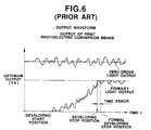
- the image developing equipment as described above produces, as shown in Fig. 6, turbulence (pulsation) in outputs of the zero order light and the first order light because of external disturbances such as dust floating in the optical path of the laser beam, fog caused by spraying the developing solution, fluctuation of the developing solution surface, or variation in laser output and the like, and so errors in development of the pits can be caused by errors in detecting the stop position of the developing process.
- turbulence pulsesation
- turbulence in the outputs of photoelectric conversion means 106 and 105 is also found to arise through unevenness of thickness of the glass base plate 101.
- the surface of the glass base plate 101 appears to be flat, but actually on the surface exist an enormous number of irregularities, and accordingly it has been found that, when for such a glass base plate 101 the laser beam is irradiated on the photoresist film as a monitor light, then as shown in Fig. 7, diffracted light "b" of the monitor light "a” and diffracted light "c” reflected on a rear surface of the glass base plate are multi-interfered with each other to produce turbulence (pulsation) in the output of the second photoelectric conversion means 106 as shown in Fig.
- An object of the present invention is to allow detection with accuracy of a stop position of the development process while avoiding being affected by disturbance from the exterior such as the dust floating in the optical path of the laser beam, the fog of developing solution, the fluctuation of the developing solution surface, and the like.
- a further object of the invention is to allow formation of pits with an accuracy in which output turbulence of the photoelectric conversion means caused by an unevenness of thickness of the glass base plate is suppressed so that the stop position of the developing process is exactly detected.
- an image developing method and equipment for use in the above type of process are characterised in that the laser beam has a decreased coherence length which is capable of preventing the diffraction light from occurrence of multiple reflection within the disk base plate which through unevenness of thickness of the disk base plate can cause fluctuations.
- the coherence length is selected in accordance with the thickness of the plate and optical path difference of multiple reflections in the plate, and preferably factors which affect the optical path difference which include the material of the plate, refractive index, laser wavelength, size of thickness variations etc.
- the coherence length is substantially less than that of a gas laser, e.g. of He-Ne type, preferably less than 1 m, more preferably less than 10 cm, more preferably less than 1 cm.
- the laser beam source is preferably a semiconductor laser as these lasers have such a suitable coherence length.
- the light amount of the laser beam irradiated on the optically sensitive film may be controlled so as to stabilise the output of the light diffracted, preferably the zero order diffracted light, by the developing pits.
- stabilisation of the zero-order light by control of the incident light allows elimination of the effects of external disturbances such as fluctuation of the surface of the developing solution and the like.
- the level of zero-order light may be stabilised to a substantially constant value or to a predetermined function of time through the developing process and this is taken into account by the control means monitoring the first order diffracted light to detect the stop point for the developing process.
- control may be effected on the laser source directly and in this case it is particularly advantageous to use a semiconductor laser.
- a controllable modulator may be placed in the path of the light incident on the optically sensitive film.
- numeral 1 depicts an image developing equipment according to a first embodiment of the invention.
- the image developing equipment 1 is so constructed that a disk base plate 3 made of glass formed thereon with a photoresist film as an optically sensitive film 2 which has been exposed to a recording beam is rotated by a rotative drive means 4 in a chamber 65, while being sprayed and supplied thereon with development solution 6 by a developing solution supply means 5.
- a rotative drive means 4 in a chamber 65
- development solution 6 by a developing solution supply means 5.
- the pits are irradiated by a monitor laser beam 8 from a laser beam source 7 and a zero order light 9 and a first order light 10 are detected by first and second photoelectric conversion means (detectors) 11 and 12 respectively, after which based on a result of such detection the supply and spray of the developing solution 6 by the developing solution supply means 5 is stopped.
- Light amount control means 13 are provided in which outputs of the zero order light 9 and first order light 10 are kept at a stable state without turbulence by controlling an output of the laser beam source 7 even when dust floats in an optical path of the laser beam, a fog of developing solution develops, the developing solution surface fluctuates etc.
- the rotative drive means 4 comprises a turntable 41 carrying the disk base plate 3 held by a vacuum, a spindle 42 attached to the turntable 41, a base plate 43 supporting the spindle 42, and a servomotor 45 for rotating the spindle 42 through a belt 44, where the disk base plate 3 is rotated by the servometer 45, through the belt 44, spindle 42, and turntable 41.
- the developing solution supply means 5 comprises a nozzle 51 arranged above the turntable 41, a nozzle arm 52 attached at one end to the nozzle 51, an arm support table 53 for rotatably supporting the other end of the nozzle arm 52 and the nozzle 51 to a tube 54. It also comprises, a solenoid valve (a cross valve) 55 for supplying the developing solution or pure water to the nozzle 51 via tube 54 and arm 52, a control circuit 56 for controlling the solenoid valve 55, and a comparison circuit 57 connected to the control circuit 56.
- a solenoid valve a cross valve
- the comparison circuit 57 is constructed to receive an output signal from the second optical conversion means 12, and has an arrangement that when the output signal reaches a developing stop level Vb, the solenoid valve 55 is operated to switch at the control circuit 56 and to supply pure water instead of the developing solution, at which developing stops by spraying of the pure water on the optical sensitive film 2 to wash away the developing solution.
- a semiconductor laser having a relatively short coherence length is used for the laser beam source 7, and the laser beam 8 with a short coherence length is adapted to irradiate, via a mirror 64, the photoresist film to monitor the development process.
- the light amount control means 13 comprises a laser driver 61 for controlling the laser beam source 7, a control circuit 62 for the laser driver 61, and a comparison circuit 63 connected to the control circuit 62 and receiving an output of the first photoelectric conversion means 11.
- the output of the semiconductor laser as a laser beam source 7 is controlled by the control circuit 62 and the laser driver 61 so that the output of the first optical conversion means 11 is kept at a stable condition irrespective of external disturbances as described above.
- the disk base plate 3 with the optically sensitive film 2 exposed by a master code cutter and the like is placed on the turntable 41, which is rotated while pure water is sprayed from the nozzle 51 so as to wash the film 2.
- the nozzle arm 52 After washing the nozzle arm 52 is rotated and then the nozzle 51 is stopped at a predetermined position on the optically sensitive film 2, and simultaneously the semiconductor laser irradiates the optically sensitive film 2.
- the developing solution 6 is sprayed from the nozzle 51 onto the optically sensitive film 2 and the spray of developing solution 6 erodes the exposed portion of the optical sensitive film 2 to start forming the pits.
- the solenoid valve 55 is operated to spray pure water from the nozzle 51 instead of the developing solution 6 so as to wash away the developing solution 6.
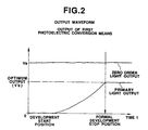
- the light amount control means 13 consisting of the comparison circuit 63, control circuit 62, and laser driver 61 controls the output of the laser beam source 7, as shown in Fig. 2, to make the output of the zero order light 9 stable and therefore turbulence of output of the first order light 10 is suppressed and this enables an accurate detect of a stop position of the developing process.
- the use of the semiconductor laser, which has a good control response characteristic, as the laser beam source facilitates this direct control of the laser beam.
- the light amount control means 13 comprises a modulator (E . 0 modulators) 71 provided in the optical path of the laser beam emitted from the laser beam source 7, a modulator driver 72 for controlling the modulator 71, a control circuit 73 for the modulator driver 72, and a comparison circuit 74 connected to the control circuit 73 and receiving an output of the first photoelectric conversion means 12.
- a modulator E . 0 modulators
- the optical sensitive film 2 and the disk base plate 3 are irradiated by a laser beam from a semiconductor laser 7 which has a relatively short coherence length. This means that no multiple interference arises in the diffraction light 9 and 10 even when unevenness is present in the thickness of the disk base plate 3. This therefore reduces turbulence in the output waveform from the second photoelectric conversion means 12 as shown in Fig. 4, and it becomes possible to more exactly detect the developing stop level Vb.
- the use of the semiconductor laser as a laser beam source 7 reduces the necessity for a laser replacement due to its longer life (semi-eternal) compared to gas lasers such as He-Ne lasers and the like, and it thus avoids the complicated time-consuming work for determining conditions for an output of the photoelectric conversion means and for forming optimum bits respectively in a laser exchange. Furthermore, smaller laser heads can be employed also advantageously permitting an improvement of freedom in design with a compact size with lower cost.
Landscapes
- Physics & Mathematics (AREA)
- General Physics & Mathematics (AREA)
- Engineering & Computer Science (AREA)
- Manufacturing & Machinery (AREA)
- Manufacturing Optical Record Carriers (AREA)
- Photosensitive Polymer And Photoresist Processing (AREA)
- Photographic Developing Apparatuses (AREA)
- Exposure And Positioning Against Photoresist Photosensitive Materials (AREA)
Claims (10)
- Bildentwicklungsvorrichtung zur Verarbeitung einer Scheiben-Grundplatte (3), die einen belichteten, optisch empfindlichen Film (2) trägt, für den Einsatz bei der Herstellung von optischen Master-Scheiben, umfassenddadurch gekennzeichnet, daß die Laserstrahlquelle (7) eine Laserlichtquelle mit einer derart verminderten Kohärenzlänge aufweist, daß die aus dem Auftreten mehrfacher Reflexionen in der Scheiben-Grundplatte (3) resultierende Interferenz vermieden ist.eine Antriebseinrichtung (41-45) für die Drehung der Scheiben-Grundplatte (3),eine Entwicklungslösungs-Abgabeeinrichtung (51) für die Abgabe einer Entwicklungslösung (6) auf den optisch empfindlichen Film (2), während die Scheiben-Grundplatte (3) durch die Antriebseinrichtung (41-45) gedreht wird, um belichtete Bereiche des optisch empfindlichen Films (2) aufzulösen,eine Laserstrahlquelle (7) zum Bestrahlen eines belichteten Bereiches während der Abgabe der Entwicklungslösung (6),eine fotoelektrische Umwandlungseinrichtung (11,12) zur Ermittlung von gebrochenem Licht (9,10) von dem belichteten Bereichund eine Steuereinrichtung (13), die auf die fotoelektrische Umwandlungseinrichtung (11,12) anspricht, um die Abgabe der Entwicklungslösung (6) auf der Grundlage eines Ergebnisses der Ermittlung des gebrochenen Lichtes stillzusetzen,
- Bildentwicklungsvorrichtung nach Anspruch 1, wobei die Laserquelle (7) eine Laserlichtquelle mit einer Kohärenzlänge ist, die mit Bezug auf die optische Wegdifferenz zwischen mehrfach innerhalb der Scheiben-Grundplatte (3) reflektierten Strahlen ausgewählt ist.
- Bildentwicklungsvorrichtung nach Anspruch 1 oder 2, wobei die Laserstrahlquelle (7) ein Halbleiterlaser ist.
- Bildentwicklungsvorrichtung nach Anspruch 1, 2 oder 3, wobei die Kohärenzlänge des Lasers wesentlich kleiner ist als 1 m, vorzugsweise wesentlich kleiner als 10 cm oder vorzugsweise wesentlich kleiner als 1 cm.
- Bildentwicklungsvorrichtung nach irgendeinem der Ansprüche 1 bis 4, wobei die fotoelektrische Umwandlungseinrichtung (11,12) zur Ermittlung von gebrochenem Licht (9,10) nullter und erster Ordnung aus dem belichteten Bereich dient und wobei die Steuereinrichtung (13) ferner eine Lichtmengen-Steuereinrichtung (61,62,63) umfaßt zur Steuerung der Intensität des auf den optisch empfindlichen Film (2) abgestrahlten Laserstrahls (8) in Abhängigkeit vom ermittelten Pegel des gebrochenen Lichtes (10) nullter Ordnung.
- Bildentwicklungsvorrichtung nach Anspruch 5, wobei die Lichtmengen-Steuereinrichtung (61,62,63) den Pegel des gebrochenen Lichtes (10) nullter Ordnung im wesentlichen konstant zu halten gestattet.
- Bildentwicklungsvorrichtung nach Anspruch 5 oder 6, wobei die Lichtmengen-Steuereinrichtung (61,62,63) eine Laser-Ansteuereinrichtung (61) zur Steuerung eines Ausgangssignals der Laserstrahlquelle (7), eine Steuerschaltung (62) für die Laser-Ansteuereinrichtung (61) und eine Vergleichsschaltung (63) umfaßt, die einen Ausgang aufweist, der mit der Steuerschaltung (62) verbunden ist und die als ein Eingangssignal das Ausgangssignal der fotoelektrischen Umwandlungseinrichtung (11) erhält.
- Bildentwicklungsanlage nach Anspruch 5 oder 6, wobei die Lichtmengen-Steuereinrichtung (71-74) einen Modulator (71), der in dem optischen Weg des Laserstrahls (8) von der Laser strahlquelle (7) zu dem optisch empfindlichen Film (2) hin vorgesehen ist, eine Modulator-Ansteuereinrichtung (72) zur Steuerung des Modulators (71), eine Steuerschaltung (73) für die Modulator-Ansteuereinrichtung (72) und eine Vergleichsschaltung (74) umfaßt, die einen mit der Steuerschaltung (73) verbundenen Ausgang aufweist und die als ein Eingangssignal ein Ausgangssignal der fotoelektrischen Umwandlungseinrichtung (11) erhält.
- Bildentwicklungsverfahren für den Einsatz bei der Verarbeitung einer Scheiben-Grundplatte (3), die einen belichteten optisch empfindlichen Film (2) trägt, zur Verwendung bei der Erzeugung optischer Master-Scheiben, umfassend die Schritte des Drehens der Scheiben-Grundplatte (3) und der gleichzeitigen Abgabe einer Entwicklungslösung (6) auf den optisch empfindlichen Film (2) zur Auflösung der belichteten Bereiche des optisch empfindlichen Films (2),gekennzeichnet durch den Schritt der Auswahl der Laserstrahlquelle (7) in Übereinstimmung mit der Dicke der Scheiben-Grundplatte (3), derart, daß die Kohärenzlänge des Lasers hinreichend kurz ist im Vergleich zu der genannten Dicke, um die Erzeugung einer Interferenz durch mehrfach reflektiertes Licht innerhalb der Scheiben-Grundplatte (3) zu vermeiden.des Bestrahlens eines belichteten Bereiches des optisch empfindlichen Filmes (2), während er durch die Entwicklungslösung (6) aufgelöst wird,des Ermittelns des Lichtes (9,10), welches von dem belichteten Bereich gebrochen wird,und des Stillsetzens der Abgabe der Entwicklungslösung (6) in Abhängigkeit von dem ermittelten Pegel des gebrochenen Lichtes,
- Bildentwicklungsverfahren nach Anspruch 9, umfassend ferner die Ermittlung von von dem belichteten Bereich gebrochenem Licht (9,10) nullter und erster Ordnung und das Steuern der Intensität des auf den optisch empfindlichen Film (2) abgestrahlten Laserstrahls (8) in Abhängigkeit vom Pegel des gebrochenen Lichtes (10) nullter Ordnung.
Applications Claiming Priority (4)
| Application Number | Priority Date | Filing Date | Title |
|---|---|---|---|
| JP66518/92 | 1992-03-25 | ||
| JP66519/92 | 1992-03-25 | ||
| JP04066518A JP3079754B2 (ja) | 1992-03-25 | 1992-03-25 | 現像方法及び現像装置 |
| JP04066519A JP3079755B2 (ja) | 1992-03-25 | 1992-03-25 | 現像装置 |
Publications (2)
| Publication Number | Publication Date |
|---|---|
| EP0562841A1 EP0562841A1 (de) | 1993-09-29 |
| EP0562841B1 true EP0562841B1 (de) | 1998-07-01 |
Family
ID=26407703
Family Applications (1)
| Application Number | Title | Priority Date | Filing Date |
|---|---|---|---|
| EP93302243A Expired - Lifetime EP0562841B1 (de) | 1992-03-25 | 1993-03-24 | Vorrichtung und Verfahren zur Entwicklung eines Bildes |
Country Status (4)
| Country | Link |
|---|---|
| US (1) | US5357304A (de) |
| EP (1) | EP0562841B1 (de) |
| AT (1) | ATE167947T1 (de) |
| DE (1) | DE69319363T2 (de) |
Cited By (1)
| Publication number | Priority date | Publication date | Assignee | Title |
|---|---|---|---|---|
| RU2214629C2 (ru) * | 1996-12-24 | 2003-10-20 | Конинклейке Филипс Электроникс Н.В. | Способ оптической записи и устройство, использующее этот способ |
Families Citing this family (3)
| Publication number | Priority date | Publication date | Assignee | Title |
|---|---|---|---|---|
| GB9307239D0 (en) * | 1993-04-07 | 1993-06-02 | Nimbus Communications Int Ltd | Method and apparatus for process control |
| US5674115A (en) * | 1994-07-06 | 1997-10-07 | Sony Corporation | Apparatus for grinding a master disc |
| KR101700547B1 (ko) * | 2004-09-17 | 2017-01-26 | 가부시키가이샤 니콘 | 노광 장치, 노광 방법 및 디바이스 제조 방법 |
Family Cites Families (16)
| Publication number | Priority date | Publication date | Assignee | Title |
|---|---|---|---|---|
| US4142107A (en) * | 1977-06-30 | 1979-02-27 | International Business Machines Corporation | Resist development control system |
| US4136940A (en) * | 1977-12-19 | 1979-01-30 | Rca Corporation | Resist development control system |
| GB2108707B (en) * | 1981-07-08 | 1985-06-19 | Pioneer Electronic Corp | Method and system for developing a photo-resist material used as a recording medium |
| JPS5857843U (ja) * | 1981-10-16 | 1983-04-19 | パイオニア株式会社 | フオトレジスト湿式現像装置 |
| US4462860A (en) * | 1982-05-24 | 1984-07-31 | At&T Bell Laboratories | End point detection |
| US4569717A (en) * | 1983-05-24 | 1986-02-11 | Dainippon Screen Mfg. Co., Ltd. | Method of surface treatment |
| US4647172A (en) * | 1985-05-17 | 1987-03-03 | Gca Corporation | Resist development method |
| JPS6263430A (ja) * | 1985-09-13 | 1987-03-20 | Mitsubishi Cable Ind Ltd | 終点検出方法 |
| FR2598508B1 (fr) * | 1986-05-09 | 1989-05-12 | Guillaume Michel | Procede et appareil de determination de fin d'attaque d'une surface gravee |
| US4857430A (en) * | 1987-12-17 | 1989-08-15 | Texas Instruments Incorporated | Process and system for determining photoresist development endpoint by effluent analysis |
| JPH01162254A (ja) * | 1987-12-18 | 1989-06-26 | Sanyo Electric Co Ltd | 光ディスク原盤の製造方法 |
| JPH01286142A (ja) * | 1988-05-12 | 1989-11-17 | Nec Corp | 現像モニタ方法 |
| JPH01298356A (ja) * | 1988-05-27 | 1989-12-01 | Hitachi Ltd | フォトレジスト湿式現像装置 |
| JPH02125764A (ja) * | 1988-11-04 | 1990-05-14 | Konica Corp | 光量安定化光源ユニット |
| JPH02137852A (ja) * | 1988-11-18 | 1990-05-28 | Dainippon Screen Mfg Co Ltd | フォトレジストの現像終点検出方法 |
| US5131752A (en) * | 1990-06-28 | 1992-07-21 | Tamarack Scientific Co., Inc. | Method for film thickness endpoint control |
-
1993
- 1993-03-22 US US08/035,251 patent/US5357304A/en not_active Expired - Fee Related
- 1993-03-24 EP EP93302243A patent/EP0562841B1/de not_active Expired - Lifetime
- 1993-03-24 AT AT93302243T patent/ATE167947T1/de not_active IP Right Cessation
- 1993-03-24 DE DE69319363T patent/DE69319363T2/de not_active Expired - Fee Related
Cited By (1)
| Publication number | Priority date | Publication date | Assignee | Title |
|---|---|---|---|---|
| RU2214629C2 (ru) * | 1996-12-24 | 2003-10-20 | Конинклейке Филипс Электроникс Н.В. | Способ оптической записи и устройство, использующее этот способ |
Also Published As
| Publication number | Publication date |
|---|---|
| DE69319363T2 (de) | 1998-10-29 |
| ATE167947T1 (de) | 1998-07-15 |
| DE69319363D1 (de) | 1998-08-06 |
| US5357304A (en) | 1994-10-18 |
| EP0562841A1 (de) | 1993-09-29 |
Similar Documents
| Publication | Publication Date | Title |
|---|---|---|
| US5231615A (en) | Carriage fixing apparatus and disk driver having such carriage fixing apparatus | |
| JPH0238283Y2 (de) | ||
| US5209813A (en) | Lithographic apparatus and method | |
| US4469424A (en) | Method and system for developing a photo-resist material used as a recording medium | |
| EP0562841B1 (de) | Vorrichtung und Verfahren zur Entwicklung eines Bildes | |
| EP0352125A3 (de) | Vorrichtung zum Steuern eines Halbleiterlasers | |
| US6738323B1 (en) | Optical disc apparatus and focusing control method in an optical disc apparatus | |
| JP3079755B2 (ja) | 現像装置 | |
| US5218400A (en) | Developing apparatus of photoresist | |
| RU2107893C1 (ru) | Способ исследования оптического диска оригинала и устройство для его осуществления | |
| JP3079754B2 (ja) | 現像方法及び現像装置 | |
| JPS5814343A (ja) | フオトレジスト湿式現像方法及び装置 | |
| JP2861073B2 (ja) | 現像装置 | |
| JPS61276320A (ja) | フオトレジスト露光装置 | |
| JPH03176838A (ja) | 現像方法及び自動現像装置 | |
| JP2815366B2 (ja) | 光ディスクの記録及び/又は再生装置 | |
| JPS55108938A (en) | Recording control system | |
| JPS60254432A (ja) | 露光装置 | |
| JPH01191350A (ja) | 露光装置 | |
| Imanishi et al. | Near-field optical head on disk mastering process | |
| US20070253312A1 (en) | Optical Storage Interface Aparatus | |
| JPH0435819B2 (de) | ||
| JPS567250A (en) | Optical recording and reproducing device | |
| JPH03249191A (ja) | スタンパ製造方法 | |
| JPH0944912A (ja) | ディスク原盤製造装置 |
Legal Events
| Date | Code | Title | Description |
|---|---|---|---|
| PUAI | Public reference made under article 153(3) epc to a published international application that has entered the european phase |
Free format text: ORIGINAL CODE: 0009012 |
|
| AK | Designated contracting states |
Kind code of ref document: A1 Designated state(s): AT DE FR GB |
|
| 17P | Request for examination filed |
Effective date: 19940302 |
|
| 17Q | First examination report despatched |
Effective date: 19960731 |
|
| GRAG | Despatch of communication of intention to grant |
Free format text: ORIGINAL CODE: EPIDOS AGRA |
|
| GRAG | Despatch of communication of intention to grant |
Free format text: ORIGINAL CODE: EPIDOS AGRA |
|
| GRAH | Despatch of communication of intention to grant a patent |
Free format text: ORIGINAL CODE: EPIDOS IGRA |
|
| GRAH | Despatch of communication of intention to grant a patent |
Free format text: ORIGINAL CODE: EPIDOS IGRA |
|
| GRAA | (expected) grant |
Free format text: ORIGINAL CODE: 0009210 |
|
| AK | Designated contracting states |
Kind code of ref document: B1 Designated state(s): AT DE FR GB |
|
| REF | Corresponds to: |
Ref document number: 167947 Country of ref document: AT Date of ref document: 19980715 Kind code of ref document: T |
|
| REF | Corresponds to: |
Ref document number: 69319363 Country of ref document: DE Date of ref document: 19980806 |
|
| ET | Fr: translation filed | ||
| PLBE | No opposition filed within time limit |
Free format text: ORIGINAL CODE: 0009261 |
|
| STAA | Information on the status of an ep patent application or granted ep patent |
Free format text: STATUS: NO OPPOSITION FILED WITHIN TIME LIMIT |
|
| 26N | No opposition filed | ||
| REG | Reference to a national code |
Ref country code: GB Ref legal event code: IF02 |
|
| PGFP | Annual fee paid to national office [announced via postgrant information from national office to epo] |
Ref country code: FR Payment date: 20020312 Year of fee payment: 10 |
|
| PGFP | Annual fee paid to national office [announced via postgrant information from national office to epo] |
Ref country code: AT Payment date: 20020313 Year of fee payment: 10 |
|
| PGFP | Annual fee paid to national office [announced via postgrant information from national office to epo] |
Ref country code: GB Payment date: 20020327 Year of fee payment: 10 |
|
| PGFP | Annual fee paid to national office [announced via postgrant information from national office to epo] |
Ref country code: DE Payment date: 20020404 Year of fee payment: 10 |
|
| PG25 | Lapsed in a contracting state [announced via postgrant information from national office to epo] |
Ref country code: GB Free format text: LAPSE BECAUSE OF NON-PAYMENT OF DUE FEES Effective date: 20030324 Ref country code: AT Free format text: LAPSE BECAUSE OF NON-PAYMENT OF DUE FEES Effective date: 20030324 |
|
| PG25 | Lapsed in a contracting state [announced via postgrant information from national office to epo] |
Ref country code: DE Free format text: LAPSE BECAUSE OF NON-PAYMENT OF DUE FEES Effective date: 20031001 |
|
| GBPC | Gb: european patent ceased through non-payment of renewal fee |
Effective date: 20030324 |
|
| PG25 | Lapsed in a contracting state [announced via postgrant information from national office to epo] |
Ref country code: FR Free format text: LAPSE BECAUSE OF NON-PAYMENT OF DUE FEES Effective date: 20031127 |
|
| REG | Reference to a national code |
Ref country code: FR Ref legal event code: ST |