EP0564157A1 - Vorrichtung zur Analyse von Teilchen - Google Patents
Vorrichtung zur Analyse von Teilchen Download PDFInfo
- Publication number
- EP0564157A1 EP0564157A1 EP93302265A EP93302265A EP0564157A1 EP 0564157 A1 EP0564157 A1 EP 0564157A1 EP 93302265 A EP93302265 A EP 93302265A EP 93302265 A EP93302265 A EP 93302265A EP 0564157 A1 EP0564157 A1 EP 0564157A1
- Authority
- EP
- European Patent Office
- Prior art keywords
- light
- fluorescence
- sample liquid
- particle
- liquid flow
- Prior art date
- Legal status (The legal status is an assumption and is not a legal conclusion. Google has not performed a legal analysis and makes no representation as to the accuracy of the status listed.)
- Withdrawn
Links
Images


Classifications
-
- G—PHYSICS
- G01—MEASURING; TESTING
- G01N—INVESTIGATING OR ANALYSING MATERIALS BY DETERMINING THEIR CHEMICAL OR PHYSICAL PROPERTIES
- G01N15/00—Investigating characteristics of particles; Investigating permeability, pore-volume or surface-area of porous materials
- G01N15/10—Investigating individual particles
- G01N15/14—Optical investigation techniques, e.g. flow cytometry
- G01N15/1429—Signal processing
- G01N15/1433—Signal processing using image recognition
-
- G—PHYSICS
- G01—MEASURING; TESTING
- G01N—INVESTIGATING OR ANALYSING MATERIALS BY DETERMINING THEIR CHEMICAL OR PHYSICAL PROPERTIES
- G01N15/00—Investigating characteristics of particles; Investigating permeability, pore-volume or surface-area of porous materials
- G01N15/10—Investigating individual particles
- G01N15/14—Optical investigation techniques, e.g. flow cytometry
- G01N15/1434—Optical arrangements
-
- G—PHYSICS
- G01—MEASURING; TESTING
- G01N—INVESTIGATING OR ANALYSING MATERIALS BY DETERMINING THEIR CHEMICAL OR PHYSICAL PROPERTIES
- G01N15/00—Investigating characteristics of particles; Investigating permeability, pore-volume or surface-area of porous materials
- G01N15/10—Investigating individual particles
- G01N15/14—Optical investigation techniques, e.g. flow cytometry
- G01N15/1456—Optical investigation techniques, e.g. flow cytometry without spatial resolution of the texture or inner structure of the particle, e.g. processing of pulse signals
- G01N15/1459—Optical investigation techniques, e.g. flow cytometry without spatial resolution of the texture or inner structure of the particle, e.g. processing of pulse signals the analysis being performed on a sample stream
-
- G—PHYSICS
- G01—MEASURING; TESTING
- G01J—MEASUREMENT OF INTENSITY, VELOCITY, SPECTRAL CONTENT, POLARISATION, PHASE OR PULSE CHARACTERISTICS OF INFRARED, VISIBLE OR ULTRAVIOLET LIGHT; COLORIMETRY; RADIATION PYROMETRY
- G01J3/00—Spectrometry; Spectrophotometry; Monochromators; Measuring colours
- G01J3/28—Investigating the spectrum
- G01J3/44—Raman spectrometry; Scattering spectrometry ; Fluorescence spectrometry
- G01J3/4406—Fluorescence spectrometry
-
- G—PHYSICS
- G01—MEASURING; TESTING
- G01N—INVESTIGATING OR ANALYSING MATERIALS BY DETERMINING THEIR CHEMICAL OR PHYSICAL PROPERTIES
- G01N15/00—Investigating characteristics of particles; Investigating permeability, pore-volume or surface-area of porous materials
- G01N15/10—Investigating individual particles
- G01N15/14—Optical investigation techniques, e.g. flow cytometry
- G01N15/1404—Handling flow, e.g. hydrodynamic focusing
-
- G—PHYSICS
- G01—MEASURING; TESTING
- G01N—INVESTIGATING OR ANALYSING MATERIALS BY DETERMINING THEIR CHEMICAL OR PHYSICAL PROPERTIES
- G01N15/00—Investigating characteristics of particles; Investigating permeability, pore-volume or surface-area of porous materials
- G01N15/10—Investigating individual particles
- G01N15/14—Optical investigation techniques, e.g. flow cytometry
- G01N2015/1477—Multiparameters
-
- G—PHYSICS
- G01—MEASURING; TESTING
- G01N—INVESTIGATING OR ANALYSING MATERIALS BY DETERMINING THEIR CHEMICAL OR PHYSICAL PROPERTIES
- G01N21/00—Investigating or analysing materials by the use of optical means, i.e. using sub-millimetre waves, infrared, visible or ultraviolet light
- G01N21/62—Systems in which the material investigated is excited whereby it emits light or causes a change in wavelength of the incident light
- G01N21/63—Systems in which the material investigated is excited whereby it emits light or causes a change in wavelength of the incident light optically excited
- G01N21/64—Fluorescence; Phosphorescence
- G01N2021/6417—Spectrofluorimetric devices
-
- G—PHYSICS
- G01—MEASURING; TESTING
- G01N—INVESTIGATING OR ANALYSING MATERIALS BY DETERMINING THEIR CHEMICAL OR PHYSICAL PROPERTIES
- G01N21/00—Investigating or analysing materials by the use of optical means, i.e. using sub-millimetre waves, infrared, visible or ultraviolet light
- G01N21/62—Systems in which the material investigated is excited whereby it emits light or causes a change in wavelength of the incident light
- G01N21/63—Systems in which the material investigated is excited whereby it emits light or causes a change in wavelength of the incident light optically excited
- G01N21/64—Fluorescence; Phosphorescence
- G01N21/6428—Measuring fluorescence of fluorescent products of reactions or of fluorochrome labelled reactive substances, e.g. measuring quenching effects, using measuring "optrodes"
- G01N2021/6439—Measuring fluorescence of fluorescent products of reactions or of fluorochrome labelled reactive substances, e.g. measuring quenching effects, using measuring "optrodes" with indicators, stains, dyes, tags, labels, marks
Definitions
- the present invention relates to apparatus for analyzing a sample liquid containing particles such as blood and urine, by irradiating the sample liquid with light, detecting signals from the particles, and analyzing the particles.
- the apparatus obtains spectra of light signals by using spectral means such as a prism or diffraction grating, so as to obtain more specific particle information.
- a fluorescent excitation (excited) light is irradiated at a sample liquid containing particles such as dyed cells, and the fluorescence emitted from the particles is detected, and the particles are classified and counted.
- An example of such apparatus is a flow cytometer. Also known is an imaging flow cytometer for picking up the particle images.
- wavelength selection means such as an optical filter and a dichroic mirror is needed.
- a corresponding plurality of optical detectors are needed.
- Japanese Laid-open Patent Hei. 2-24535 discloses a flow cytometer capable of calculating the fluorescence intensity distribution (intensity against wavelength) of the particles, by separating the fluorescence from the specimen into consecutive wavelength components by spectroscopic means, and detecting the separated wavelength components by using a one-dimensional photoelectric detector.
- the optical filter With the optical filter, however, it is difficult to separate beams of light of similar wavelengths, although it is possible to separate beams of light of very different wavelengths.
- the wavelength distribution of the light cannot be measured. That is, it is not possible to know the quantity of fluorescence of a particular wavelength that is emitted from a particular position of a cell. This may be possible by taking the cell image by using a video camera and analyzing the image, but each cell must be imaged and the image processed. Thus, the apparatus becomes complicated.
- apparatus for analyzing particles comprising: a first light source for illuminating with fluorescence excitation light a sample liquid flow containing particles; spectral means for separating fluorescence emitted in a specific direction from a particle to produce a fluorescence spectrum; amplifying means for amplifying the fluorescence spectrum produced by the spectral means; an image sensor for detecting different wavelengths of the amplified fluorescence spectrum; and signal processing means for receiving a signal from the image sensor and resetting the signal of the image sensor for each particle.
- the sample liquid is formed into a sheath flow in which the suspension of particles is covered with a laminar sheath liquid in order to align the particles in a row near the middle of the liquid flow.
- a sheath liquid is a diluent liquid or the like.
- the fluorescence emitted from the particle as a result of irradiation with the fluorescence excitation light is separated by the spectral means, and a fluorescence spectrum is obtained.
- This fluorescence spectrum is amplified by the amplifying means, such as an image intensifier, and the intensity of a range of wavelengths may be measured by the image sensor.
- the fluorescence spectra of a plurality of particles can be measured simultaneously.
- the fluorescence excitation light passing through the particle and the scattered light scattered by the particle are detected by a light detecting means, passage of the particle through a detection region may be judged by the signal processing means.
- the signal of the image sensor is reset, before the signal is read out (if the particle is not of interest) or after the signal is read out (if the particle is of interest).
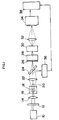
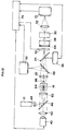
- Fig. 1 is a schematic diagram of an apparatus for analyzing particles in Embodiment 1.
- a light source 10 is a fluorescence excitation (excited) light source, which is a laser light source such as Ar,He-Cd or semiconductor laser, or a light source of continuous emission type such as Xe lamp.
- a fluorescence excitation (excited) light source which is a laser light source such as Ar,He-Cd or semiconductor laser, or a light source of continuous emission type such as Xe lamp.
- a desired excitation (excited) wavelength can be selected by using a wavelength selection filter 12.
- the filter 12 is unnecessary.
- a condensing lens 14 is a lens for focusing the light from the fluorescence excitation light source 10 into a sample liquid flow 18 flowing in the center of a flow cell 16, and the spot size when concentrated is desired to be about 10 x 200 ⁇ m.
- the flow cell 16 is made of transparent material of glass or plastics, and comprises a lead-in passage narrowed gradually, a narrow measuring passage connected to the lead-in passage, a sheath liquid feeding port provided in the lead-in passage, and a discharge port provided downstream of the measuring passage.
- Numeral 20 is a shield plate for shielding the direct light from the light source 10.
- the scattered light is reflected by a dichroic mirror 24, and enters light detecting means, such as a CCD line sensor 36.
- the signal from the line sensor 36 is fed into the signal processor 38, and passing of the particle is detected. At the same time, the size and number of passing particles are detected.
- the shield plate When sensing the particle by the transmitted light, the shield plate must be removed.
- Fig. 2 shows the characteristic diagram of the dichroic mirror 24.
- the spectroscopic means 28 is for converting the fluorescence emitted from the cell into a spectrum.
- a fluorescence spectral image as shown in Fig. 3 is obtained on the incident plane of amplifying means, such as image intensifier 30.
- Numeral 58 denotes a particle.
- the image intensifier 30 is a photoelectron multiplier, and is used for amplifying the fluorescence spectral image separated by the spectroscopic means 28.
- the fluorescence spectral image entering the incident plane (photoelectric plane) of the image intensifier 30 is amplified, and sent out to an output plane (fluorescence plane) of the image intensifier 30.
- the fluorescence spectral image sent out of the image intensifier 30 is focused on a light receiving element (image sensor) 34 by a relay lens 32 or an optical fiber.
- the fluorescence intensity of each wavelength is measured.
- a CCD line sensor or a photo diode array as the light receiving element (image sensor) 34.
- the fluorescence intensity can be measured at a resolution of 1 nm per pixel.
- a CCD line sensor When a CCD line sensor is used as a light receiving element (image sensor) 34, since it is of charge accumulation type, i.e. different to a photo diode array, the accumulated charge must be reset by some way or other (otherwise the fluorescence intensity of all passing particles is counted (added) up). Accordingly, by making use of the signal from the line sensor 36 as the light detector, the accumulated charge is read out after every passing of particle, and the charge is reset. Besides, by processing the signal from the line sensor 36, it is judged whether the particle is to be measured or not and,in the case of a particle not to be measured, the fluorescence spectral signal is reset from the CCD line sensor 34 before reading out to the signal processor 38, so that only necessary data is taken in.
- the obtained signal is processed by the signal processor 38, and the spectral data may be obtained for every passing particle.
- the position of the pixel for each wavelength signal is different. Hence, filter for removing excitation light is not needed.
- circular or rectangular slit 26 must be installed. Since the size of the slit 26 is determined by the imaging magnification of the receiving lens 22, the size of the slit 26 may be 0.2 mm in diameter in the case of, for example, the detecting region in the flow cell being 2 ⁇ m in diameter and the imaging magnification of the receiving lens 22 being 10 times.
- the flow cytometer capable of acquiring fluorescence in two or more types (kinds) of wavelengths by using one detecting system.
- the apparatus in Fig. 1 is designed to detect the forward scattered light and forward fluorescence caused by fluorescence excitation light from the light source 10, but other embodiments can be also realized.
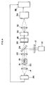
- Fig. 4 is a schematic diagram of an apparatus for analyzing particles in Embodiment 2.
- the apparatus in Fig. 4 is different from the apparatus in Fig. 1 in the configuration (arrangement) of the illumination system of the light source 10 (illumination system of fluorescence excitation light) and the scattered light detection system of the light (photo) detecting means 36, and the apparatus in Fig. 4 is intended to detect the forward scattered light and backward fluorescence.
- the excitation light from the light source 10 does not enter directly into the fluorescence detecting system, so that fluorescence measurement at high precision is realized.
- Fig. 5 is a schematic diagram of an apparatus for analyzing particles in Embodiment 3.
- the apparatus in Fig. 5 is further different from the apparatus in Fig. 4 in the arrangement of the scattered light detecting system of the light detecting means 36, and the apparatus in Fig. 5 is intended to detect the side scattered light and backward fluorescence.
- the shielding plate 20 for detecting the side scattered light is not needed.
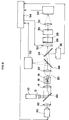
- Fig. 6 is a schematic diagram of an apparatus for analyzing particles in Embodiment 4.
- This embodiment shows an arrangement of an apparatus for picking up white light images of cells emitting fluorescence of a specific wavelength by utilizing the signal obtained in Embodiment 1.
- a pulse emission type light source in the visible light region for example, Xe flash lamp
- the irradiation light from the light source 40 is transformed into parallel light in a collimator lens 42, and enters a half-mirror 46.
- the half-mirror 46 is used for matching the irradiation regions of the excitation light source 10 and pickup light source 40, and the ratio of transmitted light and reflected light is determined freely by the quantity of light required in the fluorescence receiving system and cell pickup system, but it is desired to heighten the transmissivity of the light from the excitation light source 10 by setting the transmissivity at 90% and the reflectivity at 10% in order to intensify the fluorescence intensity.
- a half-mirror 48 is designed to pass the fluorescence obtained from the cell and reflect the cell pickup light, and the ratio of the reflected light and transmitted light can be determined according to the quantity of light required in each system, same as in the case of the half-mirror 46.
- An electronic shutter 50 is used to prevent excessive light from entering the image intensifier 30 when the cell image pickup light source 40 emits light. Instead of this electronic shutter, an image intensifier possessing a gate function may be used.
- the image pickup means for example a CCD camera 52, is intended to pick up the white light image of the cell.
- the excitation light is always entering the CCD camera, and the CCD element is saturated by the luminance (brightness), and therefore, as shown in Fig. 7, the irradiation region 56 of the excitation light source 10 and the pickup region 57 of the CCD camera 52 must be separate.
- Numeral 58 denotes a particle.
- the excitation light source 10 if the light source such as He-Cd laser for emitting the light in the wavelength outside the visible region or at the end of visible region is used, this light does not affect the color imaging of the cell.
- the signal processor 54 processes the signal from the light receiving element (image sensor) 34 and judges if the cell in the process of passing the pickup region is to be measured or not, and if judged to be the target cell a trigger pulse is generated to activate the cell image pickup light source 40, while the obtained signal is analyzed.
- the fluorescence excitation light source 10 always illuminates the particle passing region of the flow cell 16, and monitors passing of cells.
- a cell dyed with fluorescent dye passes, the fluorescence emitted from the cell and the remaining excitation light are condensed by the receiving lens 22, and pass through a half-mirror 48, and the excitation light component is removed by the dichroic mirror 24, and the remaining light passes through a circular slit 26, and enters the spectroscopic means 28.
- the fluorescence light entering the spectroscopic means 28 is separated into spectra, and passes through the electronic shutter 50, and a spectral image as shown in Fig. 3 is focused on the image intensifier 30.
- This spectral image is amplified by the image intensifier 30, and is output at the fluorescent plane of the image intensifier 30.
- the spectral image produced on the fluorescent plane of the image intensifier 30 is focused on the light receiving element 34 by the relay lens 32.
- the image instead of the relay lens 32, the image may be also focused on the light receiving element 34 by using an optical fiber.
- a similar effect is obtained when the electronic shutter 50 is disposed behind (downstream of) the spectroscopic means 28. Moreover, without using the electronic shutter 50, the same effect may be obtained by using an image intensifier with gate function.
- the detected signal is analyzed by the signal processor 54.
- the particle to be measured is dyed in FITC or phycoerythrin or in both, and hence the fluorescence wavelength emitted from the particle is either 530 nm or 570 nm, or both. Accordingly, when either one of the fluorescence intensity at 530 nm and 570 nm is more than a specific value or both are more than specific values, the white light image pickup light source 40 is activated.
- the pictured particle images are classified and stored according to fluorescence wavelength (in three types, that is, 530 nm, 570 nm, and both). Alternatively, comparing the measured fluorescence wavelength pattern with a preset fluorescence wavelength pattern, if the wavelength patterns are matched, the white light image pickup light source 40 is activated.
- the emission time of the white light image pickup light source 40 must be a sufficiently short time, otherwise the still image is not obtained. This emission time is determined by the velocity of the cell passing through the pickup region. For example, if the cell velocity is 1 m/sec, the emission time must be 1 ⁇ sec or less.
- the electronic shutter 50 is operated, so that strobe light may not enter the image intensifier 30.
- the light emitted from the white light image pickup light source 40 passes through the half-mirror 46, and irradiates the cell in the flow cell 16.
- the light passing through the cell is focused by the receiving lens 22, and is reflected by the half-mirror 48, and is focused on the CCD camera 52.
- the irradiation system of the fluorescence excitation light of the light source 10 and the irradiation system of pulse light for image pickup of the light source 40 are disposed on the same optical axis, and the detection systems of scattered light, fluorescence, and particle image light are disposed on the same optical axis so as to detect the forward scattered light, forward fluorescence and transmitted light image, but other embodiments may be also executed.
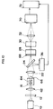
- Fig. 8 is a schematic diagram of an apparatus for analyzing particles in Embodiment 5.
- the apparatus in Fig. 8 is different from the apparatus in Fig. 6 in the arrangement of the irradiation system of fluorescence excitation light of the light source 10, and is intended to detect the side scattered light of the light source 10, side fluorescence of the light source 10, and transmitted light image of the light source 40.
- the shield plate 20 for detecting side scattered light is not needed.
- a half-mirror or dichroic mirror for reflecting the light from the light source 10 must be used as the mirror 46, and therefore the light from each light source cannot be led efficiently into the flow cell 16.
- mirror 46 since mirror 46 is not used, it is advantageous because the light from the light source 10 and the light from the light source 40 can be directly and efficiently irradiated at the flow cell 16.
- Fig. 9 is a schematic diagram of an apparatus for analyzing particles in Embodiment 6.
- the apparatus in Fig. 9 is different from the apparatus in Fig. 6 in the arrangement of the irradiation system of pulse light for particle pickup of the light source 40 and the pickup system of particle transmitted light image, and the apparatus in Fig. 9 is intended to detect the forward scattered light of the light source 10, forward fluorescence of the light source 10, and the transmitted light image of the light source 40.
- the system for picking up white light image is disposed at a position orthogonal to the optical system for detection of fluorescence.
- Numeral 15 is a condenser
- 23 is a receiving lens
- 60 is a signal processor.
- Fig. 10 is a schematic diagram of an apparatus for analyzing particles in Embodiment 7.
- the sample liquid flow is a flat flow 64, instead of a circular flow;
- the light receiving element for detecting the fluorescent spectral image is a two-dimensional image sensor 70, instead of a one-dimensional image sensor;
- the slit is a rectangular slit 68 broad (wide) in the lateral direction, instead of the circular one.
- Fig. 11 is a magnified view of essential parts of Fig. 10. Since the sample liquid flow 64 is a flat flow, the number of particles to be analyzed can be increased. Besides, using a two-dimensional image sensor 70, a spectral distribution diagram for each point in the X-direction may be obtained. Besides, in order to obtain a flat sample liquid flow 64 in the flow cell 16, the lead-in passage of the flow cell 16 is gradually narrowed in width only in one direction of the passage.
- the measuring region in the flow cell 16 For example, supposing the measuring region in the flow cell 16 to be 20 x 150 ⁇ m and the imaging magnification of receiving lens 22 to be 40 times, when the slit 68 before (upstream of) the spectroscopic means 28 is 6 x 0.8 mm, the size of one pixel is 40 ⁇ m in the light receiving element (two-dimensional image sensor) 70, and the CCD area sensor has 150 x 250 pixels (150 pixels in the X-direction, 250 pixels in the Y-direction), the fluorescent spectrum from the cell can be measured in the entire measuring region, and the wavelength resolution of 1 nm per 1 pixel of CCD can be attained.
- the wavelength of the fluorescence emitted simultaneously from a plurality of cells can be measured.
- the wavelength of the fluorescence emitted from the cells is limited in a specific wavelength region, for example, when using FITC (fluorescein isothiocyanate), phycoerythrin, and propidium iodine as fluorescent dyes, by placing the line type CCD sensor or photo diode array at the Y-axis position corresponding to the wavelengths of 530 nm, 570 nm, and 610 nm, only the intended spectral component can be measured.
- Numeral 62 is a condenser and 66 is a shield plate.
- Fig. 12 is a schematic diagram of an apparatus for analyzing particles in Embodiment 8.
- the system for white light image pickup is added to the apparatus of Embodiment 7 shown in Fig. 10.
- the signal obtained from the detector (two-dimensional image sensor) 70 is analyzed by the signal processor 74.
- the white light image pickup light source 40 is used to form a cell image in the CCD camera 52.
- Numeral 44 is a wavelength selection filter.
- the embodiments have the following characteristics.
Landscapes
- Chemical & Material Sciences (AREA)
- Dispersion Chemistry (AREA)
- Physics & Mathematics (AREA)
- Health & Medical Sciences (AREA)
- Life Sciences & Earth Sciences (AREA)
- Analytical Chemistry (AREA)
- Biochemistry (AREA)
- General Health & Medical Sciences (AREA)
- General Physics & Mathematics (AREA)
- Immunology (AREA)
- Pathology (AREA)
- Engineering & Computer Science (AREA)
- Signal Processing (AREA)
- Investigating, Analyzing Materials By Fluorescence Or Luminescence (AREA)
Applications Claiming Priority (2)
| Application Number | Priority Date | Filing Date | Title |
|---|---|---|---|
| JP10882892 | 1992-04-01 | ||
| JP108828/92 | 1992-04-01 |
Publications (1)
| Publication Number | Publication Date |
|---|---|
| EP0564157A1 true EP0564157A1 (de) | 1993-10-06 |
Family
ID=14494579
Family Applications (1)
| Application Number | Title | Priority Date | Filing Date |
|---|---|---|---|
| EP93302265A Withdrawn EP0564157A1 (de) | 1992-04-01 | 1993-03-25 | Vorrichtung zur Analyse von Teilchen |
Country Status (2)
| Country | Link |
|---|---|
| US (1) | US5422712A (de) |
| EP (1) | EP0564157A1 (de) |
Cited By (12)
| Publication number | Priority date | Publication date | Assignee | Title |
|---|---|---|---|---|
| WO1995021242A1 (en) * | 1994-02-07 | 1995-08-10 | Whitbread Plc | Monitoring the colour and bitterness of beer |
| WO1999015877A1 (en) * | 1997-09-22 | 1999-04-01 | Neles Field Controls Oy | Method and instrument for measuring fibres in suspension |
| WO1999056106A1 (en) * | 1998-04-29 | 1999-11-04 | Particle Measuring Systems, Inc. | Chemical-mechanical-planarization (cmp) slurry quality control process and particle size distribution measuring systems |
| US6087182A (en) * | 1998-08-27 | 2000-07-11 | Abbott Laboratories | Reagentless analysis of biological samples |
| WO2005074506A2 (en) | 2004-01-30 | 2005-08-18 | Nalco Company | Interchangeable tip-open cell fluorometer |
| WO2012104496A1 (fr) * | 2011-02-04 | 2012-08-09 | Horiba Abx Sas | Dispositif et procede de mesures multiparametriques de microparticules dans un fluide |
| CN101435764B (zh) * | 2007-11-12 | 2013-11-27 | 北京深迈瑞医疗电子技术研究院有限公司 | 一种粒子分析仪及粒子分析方法 |
| EP2327977A3 (de) * | 2009-11-30 | 2017-08-23 | Sysmex Corporation | Partikelanalysevorrichtung und Partikelabbildungsverfahren |
| CN107525585A (zh) * | 2011-09-13 | 2017-12-29 | 索尼公司 | 光谱分析设备、光谱分析方法以及光谱图显示的方法 |
| EP3259574A4 (de) * | 2015-02-18 | 2018-10-31 | Becton, Dickinson and Company | Optische erfassungssysteme und verfahren zur verwendung davon |
| CN112229822A (zh) * | 2020-08-25 | 2021-01-15 | 西安电子科技大学 | 对流动液体内多目标的反射式单帧散射成像装置及方法 |
| CN113508286A (zh) * | 2019-03-21 | 2021-10-15 | 贝克顿·迪金森公司 | 光检测系统及其使用方法 |
Families Citing this family (68)
| Publication number | Priority date | Publication date | Assignee | Title |
|---|---|---|---|---|
| US5772606A (en) * | 1994-03-04 | 1998-06-30 | Kyoto Dai-Ichi Kagaku Co., Ltd. | Method of and apparatus for measuring uric components |
| JPH08275063A (ja) * | 1995-04-04 | 1996-10-18 | Minolta Co Ltd | 撮像装置 |
| DE19906757B4 (de) * | 1998-02-19 | 2004-07-15 | Leica Microsystems Heidelberg Gmbh | Mikroskop |
| US6075609A (en) * | 1998-03-26 | 2000-06-13 | Antek Industrial Instruments, Inc. | Apparatus and methods for improving fluorescence detectors |
| DE19859314A1 (de) * | 1998-12-22 | 2000-06-29 | Zeiss Carl Jena Gmbh | Anordnung zur Separierung von Anregungs- und Emissionslicht in einem Mikroskop |
| DE19936573A1 (de) * | 1998-12-22 | 2001-02-08 | Zeiss Carl Jena Gmbh | Anordnung zur Separierung von Anregungs- und Emissionslicht in einem Mikroskop |
| US7450229B2 (en) * | 1999-01-25 | 2008-11-11 | Amnis Corporation | Methods for analyzing inter-cellular phenomena |
| US8005314B2 (en) * | 2005-12-09 | 2011-08-23 | Amnis Corporation | Extended depth of field imaging for high speed object analysis |
| US6249341B1 (en) | 1999-01-25 | 2001-06-19 | Amnis Corporation | Imaging and analyzing parameters of small moving objects such as cells |
| US8131053B2 (en) | 1999-01-25 | 2012-03-06 | Amnis Corporation | Detection of circulating tumor cells using imaging flow cytometry |
| US6473176B2 (en) | 1999-01-25 | 2002-10-29 | Amnis Corporation | Imaging and analyzing parameters of small moving objects such as cells |
| US6975400B2 (en) * | 1999-01-25 | 2005-12-13 | Amnis Corporation | Imaging and analyzing parameters of small moving objects such as cells |
| US7057732B2 (en) * | 1999-01-25 | 2006-06-06 | Amnis Corporation | Imaging platform for nanoparticle detection applied to SPR biomolecular interaction analysis |
| US20060257884A1 (en) * | 2004-05-20 | 2006-11-16 | Amnis Corporation | Methods for preparing and analyzing cells having chromosomal abnormalities |
| US6707551B2 (en) * | 2000-01-24 | 2004-03-16 | Amnis Corporation | Multipass cavity for illumination and excitation of moving objects |
| US6671044B2 (en) | 1999-01-25 | 2003-12-30 | Amnis Corporation | Imaging and analyzing parameters of small moving objects such as cells in broad flat flow |
| US8406498B2 (en) * | 1999-01-25 | 2013-03-26 | Amnis Corporation | Blood and cell analysis using an imaging flow cytometer |
| US6580504B1 (en) | 1999-01-25 | 2003-06-17 | Amnis Corporation | Multipass cavity for illumination and excitation of moving objects |
| US8885913B2 (en) | 1999-01-25 | 2014-11-11 | Amnis Corporation | Detection of circulating tumor cells using imaging flow cytometry |
| US6608682B2 (en) | 1999-01-25 | 2003-08-19 | Amnis Corporation | Imaging and analyzing parameters of small moving objects such as cells |
| EP1055925B1 (de) * | 1999-05-28 | 2010-09-08 | Yokogawa Electric Corporation | Biochip-Lesegerät |
| US8264680B2 (en) * | 1999-05-28 | 2012-09-11 | Yokogawa Electric Corporation | Biochip reader and electrophoresis system |
| US6934408B2 (en) * | 2000-08-25 | 2005-08-23 | Amnis Corporation | Method and apparatus for reading reporter labeled beads |
| US6778263B2 (en) * | 2000-08-25 | 2004-08-17 | Amnis Corporation | Methods of calibrating an imaging system using calibration beads |
| US6875973B2 (en) * | 2000-08-25 | 2005-04-05 | Amnis Corporation | Auto focus for a flow imaging system |
| US6583865B2 (en) * | 2000-08-25 | 2003-06-24 | Amnis Corporation | Alternative detector configuration and mode of operation of a time delay integration particle analyzer |
| US6608680B2 (en) | 2000-08-25 | 2003-08-19 | Amnis Corporation | TDI imaging system for kinetic studies |
| AU2001290568A1 (en) | 2000-08-25 | 2002-03-04 | Amnis Corporation | Measuring the velocity of small moving objects such as cells |
| US7009651B2 (en) | 2000-10-12 | 2006-03-07 | Amnis Corporation | System and method for high numeric aperture imaging systems |
| AU2002211913A1 (en) | 2000-10-12 | 2002-04-22 | Amnis Corporation | Multipass cavity for illumination and excitation of moving objects |
| US20020146734A1 (en) * | 2001-02-21 | 2002-10-10 | Amnis Corporation | Method and apparatus for labeling and analyzing cellular components |
| AU2002308693A1 (en) * | 2001-04-25 | 2002-11-05 | Amnis Corporation | Method and apparatus for correcting crosstalk and spatial resolution for multichannel imaging |
| US7190832B2 (en) | 2001-07-17 | 2007-03-13 | Amnis Corporation | Computational methods for the segmentation of images of objects from background in a flow imaging instrument |
| US6941005B2 (en) * | 2002-11-01 | 2005-09-06 | Coulter International Corp. | Monitoring and control of droplet sorting |
| JP2005006553A (ja) * | 2003-06-19 | 2005-01-13 | Olympus Corp | 細胞培養検出装置 |
| US8953866B2 (en) | 2004-03-16 | 2015-02-10 | Amnis Corporation | Method for imaging and differential analysis of cells |
| CA2598602A1 (en) | 2004-03-16 | 2005-10-20 | Amnis Corporation | Image based quantitation of molecular translocation |
| WO2005090945A1 (en) | 2004-03-16 | 2005-09-29 | Amnis Corporation | Method for imaging and differential analysis of cells |
| US7280204B2 (en) * | 2004-04-08 | 2007-10-09 | Purdue Research Foundation | Multi-spectral detector and analysis system |
| JP4763485B2 (ja) * | 2006-03-15 | 2011-08-31 | 株式会社日立ハイテクノロジーズ | 蛍光検出装置 |
| US20100032584A1 (en) * | 2006-08-18 | 2010-02-11 | Macquarie University | Tiime gated fluorescent flow cytometer |
| DE102007027008A1 (de) * | 2007-06-08 | 2008-12-11 | Spectro Analytical Instruments Gmbh & Co. Kg | Spektrometer mit Festkörpersensoren und Sekundärelektronenvervielfachern |
| US8039817B2 (en) | 2008-05-05 | 2011-10-18 | Illumina, Inc. | Compensator for multiple surface imaging |
| JP5859439B2 (ja) | 2009-08-13 | 2016-02-10 | シーメンス・ヘルスケア・ダイアグノスティックス・インコーポレイテッド | 臨床分析機によって分析される液体サンプルおよび容器の中の干渉物質および物理的寸法を確定するための方法ならびに装置 |
| US8451524B2 (en) * | 2009-09-29 | 2013-05-28 | Amnis Corporation | Modifying the output of a laser to achieve a flat top in the laser's Gaussian beam intensity profile |
| US8817115B1 (en) | 2010-05-05 | 2014-08-26 | Amnis Corporation | Spatial alignment of image data from a multichannel detector using a reference image |
| CN103308440A (zh) * | 2013-05-28 | 2013-09-18 | 香港浸会大学深圳研究院 | 一种流式荧光显微成像装置及方法 |
| US9352315B2 (en) | 2013-09-27 | 2016-05-31 | Taiwan Semiconductor Manufacturing Company, Ltd. | Method to produce chemical pattern in micro-fluidic structure |
| US9261452B2 (en) * | 2013-12-23 | 2016-02-16 | Palo Alto Research Center Incorporated | Flow cytometer |
| US10324020B2 (en) | 2013-12-23 | 2019-06-18 | Palo Alto Research Center Incorporated | Fluidic optical cartridge |
| JP6325423B2 (ja) * | 2014-10-10 | 2018-05-16 | アズビル株式会社 | 液中蛍光検出装置及び液中の蛍光の検出方法 |
| US10883931B2 (en) * | 2016-02-24 | 2021-01-05 | Sony Corporation | Optical measuring instrument, flow cytometer, and radiation counter |
| US10444088B2 (en) * | 2017-01-06 | 2019-10-15 | Newtonoid Technologies, L.L.C. | Transparent ceramic composition |
| US11293817B2 (en) | 2017-01-06 | 2022-04-05 | Newtonoid Technologies, L.L.C. | Transparent ceramic composition |
| EP3586104A4 (de) | 2017-02-27 | 2020-12-16 | Becton, Dickinson and Company | Lichtdetektionssysteme und verfahren zur verwendung davon |
| US10733918B2 (en) | 2018-04-05 | 2020-08-04 | Newtonoid Technologies, L.L.C. | Method of converting a static display to a changing display |
| NL2021377B1 (en) | 2018-07-03 | 2020-01-08 | Illumina Inc | Interposer with first and second adhesive layers |
| US10704094B1 (en) | 2018-11-14 | 2020-07-07 | Element Biosciences, Inc. | Multipart reagents having increased avidity for polymerase binding |
| US10768173B1 (en) | 2019-09-06 | 2020-09-08 | Element Biosciences, Inc. | Multivalent binding composition for nucleic acid analysis |
| US10876148B2 (en) | 2018-11-14 | 2020-12-29 | Element Biosciences, Inc. | De novo surface preparation and uses thereof |
| WO2020118255A1 (en) | 2018-12-07 | 2020-06-11 | Element Biosciences, Inc. | Flow cell device and use thereof |
| US20220244164A1 (en) * | 2019-05-30 | 2022-08-04 | Sony Group Corporation | Optical measuring device and optical measuring system |
| US11287422B2 (en) | 2019-09-23 | 2022-03-29 | Element Biosciences, Inc. | Multivalent binding composition for nucleic acid analysis |
| US12106505B2 (en) * | 2020-09-02 | 2024-10-01 | International Business Machines Corporation | Reflection-based distance perception |
| EP4012377B1 (de) * | 2020-12-09 | 2024-04-24 | Wilde, Axel | Vorrichtung und verfahren zur erfassung von partikeln in fluid-gemischen und gas-gemischen |
| AU2022322756A1 (en) | 2021-08-04 | 2024-02-08 | Becton, Dickinson And Company | Light detection systems having first and second light receivers, and methods of use thereof |
| US20250172472A1 (en) * | 2022-02-18 | 2025-05-29 | The Johns Hopkins University | Fluid analysis system and methods |
| AU2023325064A1 (en) | 2022-08-15 | 2025-03-06 | Element Biosciences, Inc. | Spatially resolved surface capture of nucleic acids |
Citations (8)
| Publication number | Priority date | Publication date | Assignee | Title |
|---|---|---|---|---|
| JPS63233353A (ja) * | 1987-03-20 | 1988-09-29 | Seiko Instr & Electronics Ltd | フロ−サイトメ−タ |
| US4793705A (en) * | 1987-10-07 | 1988-12-27 | The United States Of America As Represented By The United States Department Of Energy | Single molecule tracking |
| JPH0224535A (ja) * | 1988-07-12 | 1990-01-26 | Canon Inc | 粒子解析装置 |
| EP0442025A1 (de) * | 1990-02-08 | 1991-08-21 | Toa Medical Electronics Co., Ltd. | Optisches Teilchenanalysegerät mit zwei Arten von Lichtquellen |
| JPH03252542A (ja) * | 1990-03-02 | 1991-11-11 | Hitachi Ltd | 免疫分析方法及びその装置 |
| EP0466168A2 (de) * | 1990-07-13 | 1992-01-15 | Toa Medical Electronics Co., Ltd. | Gerät zur Teilchenbildanalyse |
| JPH0465654A (ja) * | 1990-07-05 | 1992-03-02 | Hitachi Ltd | 細胞分析装置 |
| JPH0486546A (ja) * | 1990-07-27 | 1992-03-19 | Canon Inc | 検体検査装置 |
Family Cites Families (10)
| Publication number | Priority date | Publication date | Assignee | Title |
|---|---|---|---|---|
| JPS59182341A (ja) * | 1983-03-31 | 1984-10-17 | Horiba Ltd | 試料発光の異方性測定装置 |
| US4690561A (en) * | 1985-01-18 | 1987-09-01 | Canon Kabushiki Kaisha | Particle analyzing apparatus |
| JPH0617861B2 (ja) * | 1985-02-04 | 1994-03-09 | 株式会社日立製作所 | 粒子密度計測装置 |
| US4988619A (en) * | 1987-11-30 | 1991-01-29 | United States Department Of Energy | Flow cytometry apparatus |
| US5123731A (en) * | 1988-02-01 | 1992-06-23 | Canon Kabushiki Kaisha | Particle measuring device |
| NO894680L (no) * | 1989-11-24 | 1991-05-27 | Flowtech A S V Harald Steen | Pulsmodulasjon av eksitasjonslyskilden i vaeskestroemcytofotometere. |
| JP3084295B2 (ja) * | 1991-02-27 | 2000-09-04 | シスメックス株式会社 | フローイメージサイトメータ |
| JPH0734012B2 (ja) * | 1991-02-27 | 1995-04-12 | 東亜医用電子株式会社 | フローイメージサイトメータ |
| EP0519092A1 (de) * | 1991-06-18 | 1992-12-23 | Sovetsko- Amerikanskoe Sovmestnoe Predpriyatie " Dialog" | Einrichtung zur Bestimmung von Raum- und Zeitkennlinien der schwachen optischen Emission eines Objektes |
| JP3102935B2 (ja) * | 1991-11-20 | 2000-10-23 | シスメックス株式会社 | イメージングフローサイトメータ |
-
1993
- 1993-03-18 US US08/034,376 patent/US5422712A/en not_active Expired - Fee Related
- 1993-03-25 EP EP93302265A patent/EP0564157A1/de not_active Withdrawn
Patent Citations (8)
| Publication number | Priority date | Publication date | Assignee | Title |
|---|---|---|---|---|
| JPS63233353A (ja) * | 1987-03-20 | 1988-09-29 | Seiko Instr & Electronics Ltd | フロ−サイトメ−タ |
| US4793705A (en) * | 1987-10-07 | 1988-12-27 | The United States Of America As Represented By The United States Department Of Energy | Single molecule tracking |
| JPH0224535A (ja) * | 1988-07-12 | 1990-01-26 | Canon Inc | 粒子解析装置 |
| EP0442025A1 (de) * | 1990-02-08 | 1991-08-21 | Toa Medical Electronics Co., Ltd. | Optisches Teilchenanalysegerät mit zwei Arten von Lichtquellen |
| JPH03252542A (ja) * | 1990-03-02 | 1991-11-11 | Hitachi Ltd | 免疫分析方法及びその装置 |
| JPH0465654A (ja) * | 1990-07-05 | 1992-03-02 | Hitachi Ltd | 細胞分析装置 |
| EP0466168A2 (de) * | 1990-07-13 | 1992-01-15 | Toa Medical Electronics Co., Ltd. | Gerät zur Teilchenbildanalyse |
| JPH0486546A (ja) * | 1990-07-27 | 1992-03-19 | Canon Inc | 検体検査装置 |
Non-Patent Citations (5)
| Title |
|---|
| PATENT ABSTRACTS OF JAPAN vol. 13, no. 35 (P-818)26 January 1989 & JP-A-63 233 353 ( SEIKO ) 29 September 1988 * |
| PATENT ABSTRACTS OF JAPAN vol. 14, no. 169 (P-1032)30 March 1990 & JP-A-02 024 535 ( CANON ) 26 January 1990 * |
| PATENT ABSTRACTS OF JAPAN vol. 16, no. 264 (P-1370)15 June 1992 & JP-A-04 065 654 ( HITACHI ) 2 March 1992 * |
| PATENT ABSTRACTS OF JAPAN vol. 16, no. 309 (P-1382)8 July 1992 & JP-A-04 086 546 ( CANON ) 19 March 1992 * |
| PATENT ABSTRACTS OF JAPAN vol. 16, no. 53 (P-1309)10 February 1992 & JP-A-03 252 542 ( HITACHI ) 11 November 1991 * |
Cited By (32)
| Publication number | Priority date | Publication date | Assignee | Title |
|---|---|---|---|---|
| AU677147B2 (en) * | 1994-02-07 | 1997-04-10 | Whitbread Plc | Monitoring the colour and bitterness of beer |
| US5716850A (en) * | 1994-02-07 | 1998-02-10 | Whitbread Plc | Monitoring the colour and bitterness of beer |
| WO1995021242A1 (en) * | 1994-02-07 | 1995-08-10 | Whitbread Plc | Monitoring the colour and bitterness of beer |
| US6311550B1 (en) | 1997-09-22 | 2001-11-06 | Metso Field Systems Oy | Method for measuring particles in suspension and measuring instrument |
| WO1999015877A1 (en) * | 1997-09-22 | 1999-04-01 | Neles Field Controls Oy | Method and instrument for measuring fibres in suspension |
| US6246474B1 (en) | 1998-04-29 | 2001-06-12 | Particle Measuring Systems, Inc. | Method and apparatus for measurement of particle size distribution in substantially opaque slurries |
| USRE39783E1 (en) | 1998-04-29 | 2007-08-21 | Particle Measuring Systems, Inc. | Chemical mechanical planarization (CMP) slurry quality control process and particle size distribution measuring systems |
| US6275290B1 (en) | 1998-04-29 | 2001-08-14 | Particle Measuring Systems, Inc. | Chemical mechanical planarization (CMP) slurry quality control process and particle size distribution measuring systems |
| WO1999056106A1 (en) * | 1998-04-29 | 1999-11-04 | Particle Measuring Systems, Inc. | Chemical-mechanical-planarization (cmp) slurry quality control process and particle size distribution measuring systems |
| US6087182A (en) * | 1998-08-27 | 2000-07-11 | Abbott Laboratories | Reagentless analysis of biological samples |
| US6365109B1 (en) | 1998-08-27 | 2002-04-02 | Abbott Laboratories | Reagentless analysis of biological samples |
| US6426045B1 (en) | 1998-08-27 | 2002-07-30 | Abbott Laboratories | Reagentless analysis of biological samples |
| US6773922B2 (en) | 1998-08-27 | 2004-08-10 | Abbott Laboratories | Reagentless analysis of biological samples |
| EP2267435A1 (de) | 2004-01-30 | 2010-12-29 | Nalco Company | Fluorometer mit auswechselbarer Spitze und offener Zelle |
| CN100559164C (zh) * | 2004-01-30 | 2009-11-11 | 纳尔科公司 | 可更换探头-开放式样品池荧光计 |
| WO2005074506A2 (en) | 2004-01-30 | 2005-08-18 | Nalco Company | Interchangeable tip-open cell fluorometer |
| EP1718953A4 (de) * | 2004-01-30 | 2008-02-20 | Nalco Co | Fluorometer mit auswechselbarer spitze und offener zelle |
| CN101435764B (zh) * | 2007-11-12 | 2013-11-27 | 北京深迈瑞医疗电子技术研究院有限公司 | 一种粒子分析仪及粒子分析方法 |
| EP2327977A3 (de) * | 2009-11-30 | 2017-08-23 | Sysmex Corporation | Partikelanalysevorrichtung und Partikelabbildungsverfahren |
| FR2971337A1 (fr) * | 2011-02-04 | 2012-08-10 | Horiba Abx Sas | Dispositif et procede de mesures multiparametriques de microparticules dans un fluide |
| CN103339489A (zh) * | 2011-02-04 | 2013-10-02 | 赫拉巴Abx公司 | 用于流体中微粒子的多参数测量的设备和方法 |
| US9140645B2 (en) | 2011-02-04 | 2015-09-22 | Horiba Abx Sas | Device and method for multiparametric measurements of microparticles in a fluid |
| WO2012104496A1 (fr) * | 2011-02-04 | 2012-08-09 | Horiba Abx Sas | Dispositif et procede de mesures multiparametriques de microparticules dans un fluide |
| CN107525585A (zh) * | 2011-09-13 | 2017-12-29 | 索尼公司 | 光谱分析设备、光谱分析方法以及光谱图显示的方法 |
| CN107525585B (zh) * | 2011-09-13 | 2020-09-18 | 索尼公司 | 光谱分析设备、光谱分析方法以及光谱图显示的方法 |
| EP3259574A4 (de) * | 2015-02-18 | 2018-10-31 | Becton, Dickinson and Company | Optische erfassungssysteme und verfahren zur verwendung davon |
| US10184879B2 (en) | 2015-02-18 | 2019-01-22 | Becton, Dickinson And Company | Optical detection systems and methods of using the same |
| CN113508286A (zh) * | 2019-03-21 | 2021-10-15 | 贝克顿·迪金森公司 | 光检测系统及其使用方法 |
| EP3942279A4 (de) * | 2019-03-21 | 2022-12-28 | Becton, Dickinson and Company | Lichtdetektionssysteme und verfahren zur verwendung davon |
| US11953420B2 (en) | 2019-03-21 | 2024-04-09 | Becton, Dickinson And Company | Light detection systems and methods of use thereof |
| CN112229822A (zh) * | 2020-08-25 | 2021-01-15 | 西安电子科技大学 | 对流动液体内多目标的反射式单帧散射成像装置及方法 |
| CN112229822B (zh) * | 2020-08-25 | 2022-05-13 | 西安电子科技大学 | 对流动液体内多目标的反射式单帧散射成像装置及方法 |
Also Published As
| Publication number | Publication date |
|---|---|
| US5422712A (en) | 1995-06-06 |
Similar Documents
| Publication | Publication Date | Title |
|---|---|---|
| US5422712A (en) | Apparatus for measuring fluorescent spectra of particles in a flow | |
| JP3260469B2 (ja) | 粒子分析装置 | |
| US5644388A (en) | Imaging flow cytometer nearly simultaneously capturing a plurality of images | |
| EP0501005B1 (de) | Bildgebender Durchflusszytometer | |
| EP0501006B1 (de) | Bildgebender Durchflusszytometer | |
| CA2395627C (en) | Imaging and analyzing parameters of small moving objects such as cells | |
| EP0564122A1 (de) | Vorrichtung zur Analyse von Teilchen | |
| EP1347285B1 (de) | Verfahren und vorrichtung zur fluoreszenzlumineszenzmessung | |
| US6671044B2 (en) | Imaging and analyzing parameters of small moving objects such as cells in broad flat flow | |
| EP0501008B1 (de) | Durchfluss-Abbildungszytometer | |
| EP0538551B1 (de) | Bildgebender Durchflusszytometer | |
| US6473176B2 (en) | Imaging and analyzing parameters of small moving objects such as cells | |
| US6608682B2 (en) | Imaging and analyzing parameters of small moving objects such as cells | |
| US5072128A (en) | Defect inspecting apparatus using multiple color light to detect defects | |
| US11041756B2 (en) | Method and apparatus of filtering light using a spectrometer enhanced with additional spectral filters with optical analysis of fluorescence and scattered light from particles suspended in a liquid medium using confocal and non confocal illumination and imaging | |
| JP2002535614A (ja) | 改良したフローサイトメトリの装置および方法 | |
| CN103460027B (zh) | 差分扫描成像系统和方法 | |
| JPH10253624A (ja) | 粒子測定装置 | |
| US6040907A (en) | Microscope system for the detection of emission distribution and process for operation of the same | |
| CA2401614C (en) | Imaging and analyzing parameters of small moving objects such as cells | |
| JPH02304332A (ja) | 粒子計測装置 | |
| JP2814390B2 (ja) | 欠陥検査装置 | |
| JPH09257689A (ja) | 粒子解析装置 |
Legal Events
| Date | Code | Title | Description |
|---|---|---|---|
| PUAI | Public reference made under article 153(3) epc to a published international application that has entered the european phase |
Free format text: ORIGINAL CODE: 0009012 |
|
| AK | Designated contracting states |
Kind code of ref document: A1 Designated state(s): DE FR GB IT |
|
| STAA | Information on the status of an ep patent application or granted ep patent |
Free format text: STATUS: THE APPLICATION IS DEEMED TO BE WITHDRAWN |
|
| 18D | Application deemed to be withdrawn |
Effective date: 19940407 |