EP0565268B1 - Schneckenzentrifuge mit unterbrochenen Schneckenwendeln im konischen Austragsmantelteil - Google Patents
Schneckenzentrifuge mit unterbrochenen Schneckenwendeln im konischen Austragsmantelteil Download PDFInfo
- Publication number
- EP0565268B1 EP0565268B1 EP93302224A EP93302224A EP0565268B1 EP 0565268 B1 EP0565268 B1 EP 0565268B1 EP 93302224 A EP93302224 A EP 93302224A EP 93302224 A EP93302224 A EP 93302224A EP 0565268 B1 EP0565268 B1 EP 0565268B1
- Authority
- EP
- European Patent Office
- Prior art keywords
- bowl
- heavy phase
- conveyor
- decanter centrifuge
- hub
- Prior art date
- Legal status (The legal status is an assumption and is not a legal conclusion. Google has not performed a legal analysis and makes no representation as to the accuracy of the status listed.)
- Expired - Lifetime
Links
Images



Classifications
-
- B—PERFORMING OPERATIONS; TRANSPORTING
- B04—CENTRIFUGAL APPARATUS OR MACHINES FOR CARRYING-OUT PHYSICAL OR CHEMICAL PROCESSES
- B04B—CENTRIFUGES
- B04B1/00—Centrifuges with rotary bowls provided with solid jackets for separating predominantly liquid mixtures with or without solid particles
- B04B1/20—Centrifuges with rotary bowls provided with solid jackets for separating predominantly liquid mixtures with or without solid particles discharging solid particles from the bowl by a conveying screw coaxial with the bowl axis and rotating relatively to the bowl
-
- B—PERFORMING OPERATIONS; TRANSPORTING
- B04—CENTRIFUGAL APPARATUS OR MACHINES FOR CARRYING-OUT PHYSICAL OR CHEMICAL PROCESSES
- B04B—CENTRIFUGES
- B04B1/00—Centrifuges with rotary bowls provided with solid jackets for separating predominantly liquid mixtures with or without solid particles
- B04B1/20—Centrifuges with rotary bowls provided with solid jackets for separating predominantly liquid mixtures with or without solid particles discharging solid particles from the bowl by a conveying screw coaxial with the bowl axis and rotating relatively to the bowl
- B04B2001/2041—Centrifuges with rotary bowls provided with solid jackets for separating predominantly liquid mixtures with or without solid particles discharging solid particles from the bowl by a conveying screw coaxial with the bowl axis and rotating relatively to the bowl with baffles, plates, vanes or discs attached to the conveying screw
-
- B—PERFORMING OPERATIONS; TRANSPORTING
- B04—CENTRIFUGAL APPARATUS OR MACHINES FOR CARRYING-OUT PHYSICAL OR CHEMICAL PROCESSES
- B04B—CENTRIFUGES
- B04B1/00—Centrifuges with rotary bowls provided with solid jackets for separating predominantly liquid mixtures with or without solid particles
- B04B1/20—Centrifuges with rotary bowls provided with solid jackets for separating predominantly liquid mixtures with or without solid particles discharging solid particles from the bowl by a conveying screw coaxial with the bowl axis and rotating relatively to the bowl
- B04B2001/205—Centrifuges with rotary bowls provided with solid jackets for separating predominantly liquid mixtures with or without solid particles discharging solid particles from the bowl by a conveying screw coaxial with the bowl axis and rotating relatively to the bowl with special construction of screw thread, e.g. segments, height
Definitions
- the present invention relates to an improved decanter centrifuge. Specifically the present invention relates to a decanter centrifuge wherein the flights of the conveyor discontinue within a portion of the length of the bowl, such that the separated heavy phase material is no longer conveyed by the differential rotation of the conveyor with respect to the bowl within that portion of the bowl, and wherein a restriction is formed at the heavy phase discharge end of the bowl.
- a decanter centrifuge generally includes a rotating bowl, typically having a cylindrical portion and a frusto-conical end portion.
- the rotation of the bowl creates a centrifugal force which separates a liquid feed mixture into its constituent parts.
- the feed mixture within the bowl forms a cylindrical pond, with a ring or layer of separated heavy material adjacent the inside of the bowl wall and a ring or layer of lighter material radially inward of the heavy material layer.
- the terms "heavy phase” and "light phase” are employed hereinafter to describe materials which are separable from the feed mixture by the decanter centrifuge through the application of centrifugal force.
- the light phase material will usually be a liquid and the heavy phase material will usually be a mixture of solids and liquid.
- the liquid feed mixture introduced into the bowl generally has a specific concentration of suspended solids or other insoluble material therein. These "solids” are generally concentrated by the centrifugal force to form a heavy phase or mixture of varying concentration within the rotating bowl, including coarse solids, fine solids and liquid. Because of the varying degrees in density of the solids as well as the varying degrees of centrifugal force acting on those solids within the bowl, the concentration of the separated heavy phase may vary within the bowl. The concentration of the heavy materials that do not settle from the liquid material also varies.
- a screw conveyor rotates inside the bowl at a slightly different speed from the bowl.
- the flights of the screw conveyor push the separated heavy phase along the inside of the bowl wall towards the conical end of the bowl.
- Discharge ports for the separated heavy phase are located at the small diameter of the conical bowl portion.
- the separated light phase liquid is discharged by flowing from the cylindrical pond through separate discharge ports.
- the light phase liquid discharge ports are located, typically, at the opposite end of the bowl from the heavy phase discharge ports.
- Separation of the heavy phase materials from the feed mixture is a function of the residence time of the mixture in the bowl, a function of the feed rate, and the ability of the centrifuge to separately discharge the heavy and light phase materials.
- the purpose of the decanter centrifuge is to separately discharge a concentrated heavy phase and a clarified liquid. In order for the heavy phase to be discharged, it must be moved up the incline of the conical end portion of the bowl, called the beach, against the centrifugal force component acting in the opposite direction downward along the beach.
- Ambler U.S. Pat. No. 3,172,851 describes the operation of a decanter centrifuge with the liquid discharge weirs set at a "negative dam" or "above spillover" position, i.e., at a position radially-inward of the weir surface of the heavy phase discharge ports.
- the Ambler-type operation takes advantage of the force of the liquid on the heavy phase along the entire length of the beach to help the conveyor move heavy phase material up the beach toward the heavy phase discharge ports.
- the relative radial difference between the weir surfaces is intended to be slight.
- the Ambler-type operation relies on the cohesive nature of the heavy phase material to form a dam that prevents the liquid head (the height of the liquid layer radially inward of or above the heavy phase discharge weir surface) from washing over the heavy phase weir surface.
- the heavy phase layer in the conical end of the bowl is totally immersed in the liquid until the moment before discharge. Therefore, the heavy phase will be relatively wet.
- the heavy phase In a"below spillover"type operation, the heavy phase emerges from the liquid on the beach and is subjected to a drying action prior to discharge.
- the cohesive nature of the heavy phase material may be inconsistent. If a breakdown in the heavy phase dam formed at the heavy phase discharge weir occurs, a "washout" results. A washout is the result of the liquid head moving over the heavy phase discharge weir and, thus, a breakdown of the desired separate discharge of heavy and light phases.
- the operation of a decanter centrifuge is generally required to be steady and continuous, that is, without constant operator assistance. If a washout occurs, substantial modification of the operation of the decanter centrifuge is required in order to rebuild the heavy phase dam at the discharge weir and to again achieve steady state operation. Moreover, in order to avoid a washout, constant supervision of the centrifuge may be required.
- the Lee U.S. Pat. No. 3,795,361 also teaches the operation of a decanter centrifuge in an "above spillover" condition.
- the Lee decanter centrifuge includes an annular baffle mounted on the screw conveyor.
- the baffle which may be made in a number of forms, such as a disc or a cone, extends radially outward from the conveyor hub to a distance where its peripheral edge is in a closely spaced relationship with the inside bowl wall.
- the outside diameter of the baffle penetrates into the outer, heavy phase layer to form a restricted passageway.
- the restricted passageway permits the underflow of only heavy phase material at the bowl wall, past the baffle, and into the conical end of the bowl.
- the baffle divides the bowl into a cylindrical separating zone, where the centrifugal force separates the heavy phase from the light phase liquid, and a discharge zone, where only heavy phase is present.
- the Lee decanter centrifuge creates a centrifugal pressure head within the separating zone. This pressure head is the result of the liquid weir being radially inward of the heavy phase discharge weir. This pressure head acts in cooperation with the baffle to provide a supplemental discharge force that assists the screw conveyor in discharging the heavy phase material. This supplemental force created in the separating zone is applied to the separated heavy phase, through the restricted passageway formed by the baffle, and into the discharge zone.
- the centrifugal pressure head applies a force that assists the conveyor in advancing the heavy phase material up the beach to the discharge ports.
- Epper, et al. U.S. Pat. No. 4,617,010 shows a decanter centrifuge and/or a nozzle-type centrifuge having a series of projections mounted on the bowl wall along a conical portion thereof so as to create a conveying action in addition to a shearing action on the heavy phase prior to reaching the discharge port.
- the shearing elements in Epper are formed to assist the discharge of the heavy phase solids up the beach toward the discharge port and, thus, replaces the flights of the conveyor.
- the Epper shearing elements are also shown in conjunction with a Lee-type baffle. However, the operation of the various Epper decanter centrifuges appears to be in a below spillover condition.
- Difficult-to-convey materials are typically found in the operation of a waste water treatment plant.
- a thickening type operation results in a.concentration of the discharged heavy phase material between 3% to 10% solids by weight.
- a dewatering-type operation produces a heavy phase discharge which has a concentration in excess of 10% solids (by weight), such that the result heavy phase may be disposed of by trucking or incineration.
- chemicals are used to condition feed materials to assist settling and/or coagulation of the solids in the formation of the heavy phase.
- Such chemicals are typically known as polymers, polyelectrolytes or flocculents.
- polymers are almost always required.
- chemicals may or may not be used depending on the type of centrifuge, the nature of the feed material, and the desired heavy phase output concentration. It should be noted that the nature of the heavy phase material varies greatly from application to application due to the specific processes under which the feed material has been placed. Moreover, the application of chemicals to the feed mixture results in a more easily conveyable heavy phase material.
- DE-C-977627 which discloses the preamble of claims 1 and 20, there is described a decanter centrifuge in which over a major part of the length of the screw conveyor the wall of the bowl is located radially inwardly of the liquid phase outlet ports, and the screw conveyor moves the separated heavy phase along this major part to the outlet for the heavy phase where a damming ring is mounted on the conveyor to restrict the outlet so that in the region of the outlet the heavy phase material is subjected to compression due to the conveyor flights for additional dewatering.
- DE-A-4041162 describes a decanter centrifuge in which included within the conveyor flights which extend to the heavy phase discharge outlet are devices, which can be pneumatically or hydraulically expanded, to compress and dewater the heavy phase material during its conveyance to the heavy phase discharge outlet.
- the present invention has for its object to provide an improved decanter centrifuge capable of operation under above spillover condition.
- the invention provides a decanter centrifuge for separating a liquid feed mixture into its respective components by forming light phase material and a heavy phase material and for separately discharging the two phases, the centrifuge comprising:
- the invention provides a decanter centrifuge as set forth in claim 20.
- the decanter centrifuge of the invention is of the type typically including a cylindrical bowl mounted to rotate about its longitudinal axis and having a conical end portion.
- the decanter centrifuge includes heavy phase discharge ports within the conical end and liquid discharge ports positioned at the opposite end of the bowl.
- a helical screw conveyor is coaxially positioned within the bowl and extends along the inside length of the bowl.
- the conveyor flights are discontinuous within the conical end of the bowl.
- the conveyor is rotated at a relative speed with respect to the bowl to move the separated heavy phase along the inside surface of the bowl toward the conical end. Because of the discontinuation of the conveyor flights within the conical portion of the bowl, it is contemplated that the heavy phase material will build up along the beach and substantially fill the conical portion. Depending on the nature of the heavy phase material, the build-up may be great enough to form a pile which is radially inward of the heavy phase discharge ports. This condition will likely occur in a dewatering type operation, where the heavy phase is relatively easy-to-convey, having a firm, cohesive nature and having been treated by chemicals.
- a disc can be provided adjacent to the heavy phase discharge ports. This disc restricts the annular passageway between the beach and the hub of the screw conveyor directly adjacent to the heavy phase discharge ports. The restricting disc adjacent to the heavy phase discharge ports serves to maintain the build-up of heavy phase material and to prevent washouts.
- the decanter centrifuge of the present invention may operate in an above spillover condition with the liquid discharge weirs being radially inward of the heavy phase discharge weirs.
- This above spillover condition within the present invention serves to assist in discharging the heavy phase material through the restriction formed by the restricting disc and the beach adjacent to the heavy phase discharge ports.
- the operation of the decanter centrifuge is similar to an Ambler-type operation.
- the dam at the discharge end of the bowl is substantially increased by the discontinuation of the conveyor flights in the beach area.
- the decanter centrifuge of the present invention operating in an above spillover condition will result in an increase in the overall dryness of the heavy phase cake being discharged.
- the nature and extent of the above spillover condition will depend on the heavy phase material and the overall operation of the centrifuge, including the application of chemicals. Other features and advantages of the invention are also contemplated.
- Figure 1 is a cross-sectional view of a decanter centrifuge in accordance with the present invention.
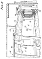
- Figure 2 is a partial cross-sectional view of the decanter centrifuge of Figure 1 which illustrates a contemplated solids profile in accordance with the present invention.
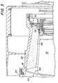
- Figure 3 shows a partial cross-sectional view of an alternate embodiment of the decanter centrifuge of the present invention.
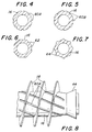
- FIGS 4-8 show variation of the conveyor hub portion of the centrifuge of the present invention.
- Figures 9 and 10 shown variation of the restricting disc portion of the present invention, including a variable restriction force.
- Figures 11-13 shown still further variations of a restriction means for a decanter centrifuge as contemplated by the present invention.
- the decanter centrifuge 10 includes a solid imperforate bowl 12 and a coaxially mounted screw conveyor 14.
- the screw conveyor 14 includes a series of flights 18 mounted on a central hub 16.
- the bowl 12 includes a cylindrical portion 20 and a frusto-conical or angled portion 22.
- the bowl 12 is mounted for rotation about its central longitudinal axis and is supported at opposite ends by bearings 24.
- the bowl 12 is rotated by motor 26, through a belt and pulley system 28.
- the conveyor 14 is rotated by a second motor 30.
- the relative rotational speed of the conveyor 14 with respect to the bowl 12 is created through gear box 32 connected to second drive motor 30 via flexible coupling 34.
- a feed mixture is introduced into the bowl 12 through feed nozzles 36.
- the centrifugal force created by the rotation of the bowl 12 causes a separation of the feed mixture into light and heavy phases (shown in Figures 2 and 3) in substantially concentric layers surrounding the axis of the bowl.
- the relative rotation of the screw conveyor 14 with respect to the bowl 12 results in the screw flights 18 moving the separated heavy phase material along the inside bowl wall toward the conical portion 22.
- the flights 18 discontinue. This discontinuation of the flights creates a beach area which is relatively flightless.
- a series of discharge ports 38 for the heavy phase material At the top of the beach is provided a series of discharge ports 38 for the heavy phase material.
- a series of light phase discharge ports 40 At the opposite end of the bowl 12 is provided a series of light phase discharge ports 40.
- Weir plates 42 are attached to the bowl face adjacent to the light phase discharge ports 40 to define the radial surface of the light phase discharge weir.
- Weir plates 42 are radially adjustable such that the relative position of the light phase discharge to the heavy phase discharge is variable.
- the centrifuge could be fitted with an inflatable dam on the liquid side of the bowl face, such as that described in commonly assigned Application Serial No. 07/711,479 filed June 6, 1991. This '479 application is herein incorporated by reference.
- the inflatable dam type structure (not shown) could be utilized for the purpose of optimizing the pond level without requiring the stopping of the centrifuge to make adjustments.
- the restricting disc 44 is formed closely adjacent the heavy phase discharge ports 38 at the relatively smaller diameter of the beach.
- the amount of restriction formed by disc 44 will be dependent upon various operational conditions of the decanter centrifuge and the desires of the centrifuge designers.
- the profile of the disc 44 which is tapered or angled toward the center of the decanter centrifuge 10, may also vary in order to achieve preferred operational conditions. Some of these variations will be discussed hereinbelow.
- Figure 2 there is illustrated in greater detail the decanter centrifuge 10 as generally shown in Figure 1.
- Figure 2 also illustrates what is believed to be a potential profile for the heavy phase layer 46 and the light phase layer 48 within the bowl 12. These profiles, however, are not necessarily accurate, but are artistic represensation used as illustrations for purposes of understanding the operation of the present invention.
- the demarcation line at interface 50 between the heavy phase material 46 and the light phase layer 48 is illustrated to be abrupt. It is contemplated that this interface 50 may be a transition zone wherein the concentration of heavy phase varies significantly.
- the nature and scope of interface 50 between the light phase layer 48 and the heavy phase 46 is generally understood in the art.
- feed ports 36 generally introduce a feed mixture into the bowl 12 at a position adjacent the connection between the cylindrical portion 20 and the conical portion 22.
- the general concentration of the "solids" within the heavy phase and the liquid light phase may greatly vary in this "feed zone".
- the heavy phase layer 46 is shown as increasing in thickness as it approaches the conical portion 22 of the bowl 12. Because the flights 18 of conveyor 14 are discontinuous in the conical bowl portion 22, the heavy phase layer 46 builds up. This is a combination of the lack of further conveyance of the material along the beach and the continuous introduction of heavy phase material by the conveyor flights 18 from the cylindrical portion 20 into the conical portion 22 of the bowl 12. It has been found through testing that the build-up of heavy phase may approach and contact the hub 16 of the conveyor 14. As illustrated, the profile of the heavy phase material 46 includes a maximum that contacts the hub 16 forming a taper thereafter toward the heavy phase discharge ports 38.
- the restricting disc 44 contacts the profile of heavy phase 46 as it approaches the discharge ports 38.
- Restricting disc 44 as illustrated in Figure 2, is in the form of an annular ring which is attached to the hub 16 of the conveyor 14 by means of a screw thread 52.
- Set screws 54 may also be used to maintain the restricting disc 44 in its set position during rotation of the conveyor 14. Rotation of the restricting disc 44 on the hub 16 adjusts the axial position of the restricting disc with respect to the discharge openings 38.
- Restricting disc 44 has a frusto-conical configuration with a straight tapered surface.
- the restricting disc 44' includes an arcuate tapered surface.
- the light phase layer 48 is positioned radially inward of the heavy phase discharge port weir surface 56.
- the large build-up of heavy phase material 46 serves as a solids dam for the head of light phase 48 positioned above weir surface 56.
- an Ambler-type operation is contemplated.
- the heavy phase build-up in the decanter centrifuge of the present invention is contemplated to be in excess of that in a typical Ambler-type operation.
- the build-up may extend radially inward of the position of the light phase layer 48.
- the hydraulic assistance toward discharge being provided by the head of liquid 48, but there is a transitional drying zone within the conical portion 22 of the bowl for the heavy phase build-up 46.
- the Lee operation includes an annular baffle for the passage of only the heavy phase material between the inside of the bowl wall and the outside of the baffle. Therefore, the separation of the heavy and light phase materials is discontinued when the heavy phase material passes under the baffle. Any separation of light phase that could occur after passing the baffle would still be discharged with the heavy phase from the heavy phase discharge ports, since the liquid has no way to return toward the light phase discharge ports.
- a Lee type baffle could be used with the present invention in certain conditions, such structure is not preferred.
- the present invention will take advantage of the additional length of the bowl that is made available for separation to occur. This feature of the invention also provides for additional residence time of the feed mixture in the bowl and thus improves separation of the phases.
- FIG. 2 there is illustrated a series of projections 58 extending from the bowl hub 16 in the flightless portion of the centrifuge 10.
- the projections 58 are provided to stir or shear the heavy phase material 46 in the conical portion of the bowl where the flights are not included in an attempt to release entrained liquid from the heavy phase material and aid in its rise to the inner surface of the heavy phase layer 46.
- projections of the type in Epper, et al. U.S. Pat. No. 4,617,010 may be provided, it is generally desired that the projections 58 of the present invention do not include a discharge assist in this conical portion 22 of the bowl 12.
- the projections 58 were to include a significant conveying function as in this Epper patent, these structures would serve to reduce the profile of the heavy phase 46 in the conical end 22 of the bowl 12 and increase the possibility of a washout. In the present invention, it is the build-up of heavy phase that is contemplated to prevent a washout from occurring. It is also contemplated that modifications to the restricting disc may compensate for this variation in build-up, if the stirring elements are considered desirable. It is contemplated, however, that the restricting disc will contact the heavy phase build-up adjacent to the heavy phase discharge ports at the small diameter of the conical portion of the bowl.
- the restricting disc 44 will cause the heavy phase material to be compressed axially as it approaches the discharge ports 38. This compression may allow for further separation of the liquid from the heavy phase. However, because the heavy phase is contemplated to be in contact with the conveyor hub 16, the liquid that may separate will possibly be blocked from returning back toward the cylindrical bowl portion 20 so as to be discharged from the light phase discharge ports 40.
- the surface of the conveyor hub 16 in the flightless portion of the centrifuge may be provided with a series of guides.
- These guides include grooves 60A in Figures 4 and 8, grooves 60B in Figure 5, flats 62 in Figure 6, and raised ribs 64 in Figure 7.
- These guide elements 60A, 60B, 62, and 64 on the outside surface of the conveyor hub 16 provide channels for the return of the separated light phase toward the cylindrical bowl portion 20.
- the guide elements such as grooves 60A, are provided along the outside surface of the conveyor hub 16 and may extend into the area of the flights 18. In this flighted area, openings are provided in the conveyor flights 18 to permit the liquid to pass back further into the bowl 12 to the area of the feed ports 36.
- the grooves 60A as illustrated are spiralled along the surface of the conveyor hub 16 in a direction opposite of the spiral of the conveyor flights 18. This opposite spiral will further aid in the return of the liquid to the light phase in pond 48.
- the guide elements could be axial or spiralled in any manner as desired.
- the last turns of the conveyor flights 18 may be varied in pitch from the remaining portions of the conveyor 14.
- the variation of the pitch is contemplated to be either an increase or a decrease as the flights approach the heavy phase discharge end depending on the conditions of the feed material.
- FIGS 9 and 10 there is illustrated further embodiments of a restricting disc portion of the present invention.
- the restricting discs 66 and 68 respectively, include means for adjusting the amount of restriction provided on the heavy phase adjacent the discharge ports 38. This adjustment of the restriction may be used to accommodate changes or variations in the feed material resulting in different or variable qualities of the heavy phase.
- the embodiment of the restricting disc 66 in Figure 9 includes a conical collar portion 70 attached to the mount 72 at one end and having a series of fingers 74 which extend from the inside surface of the collar 70 into contact with the mount 72, adjacent the conveyor hub 16.
- the collar 70 is contemplated to be made of a rubber or other resilient material.
- the fingers 74 create a force on the collar 70 due to their pivoting action about pivot 71.
- the movement of the fingers 74 is created by the centrifugal force of the rotation of the conveyor 14.
- the discharging action of the heavy phase material from the discharge ports 66 works against the outward movement of the fingers 74 and the collar 70.
- the maximum extension of the collar 70 is controlled by stop 73 which is engaged by tab 75 on the finger 74.
- the heavy phase discharge is restricted not only by the form of the restricting disc 66 but the resilience of the collar 70 and finger 74 combination. As the heavy phase is moved through the restriction, the compression force will be nearly constant as the collar 70 adjusts for changes in discharge rate of the heavy phase material.
- the fixed restriction 44 as shown in the previously discussed figures provides an optimum profile for the heavy phase material in the bowl at only one discharge rate.
- the variable restriction of Figure 9 provides a nearly constant profile for the heavy phase material for varying discharge rates.
- FIG 10 there is shown a restricting disc 68 whereby the adjustment may be remotely controlled during operation of the centrifuge.
- the restricting disc 68 in this embodiment includes collar portion 76 which is bonded to the mount 78 at the small end and fixedly mounted at the large end by means of stop plate 80 and bolt 82.
- This mounting structure for the collar 76 which is preferably made of rubber or a resilient material, forms a cavity 84 adjacent the mount 78.
- a feed passageway 86 is provided in the mount 78 such that a control liquid may be fed into the cavity 84. The control liquid is used to vary the inflation of the collar 76 and thus the size of the restriction formed by disc 68.
- Passageway 86 communicates with a reservoir 88 formed on the inside surface of the mount 78.
- Control of the inflation of collar 76 is provided by a control liquid feed system, including a leak bushing 90 and feed supply 92.
- the leak bushing 90 is provided in reservoir 88 for exhaust of the control liquid.
- a series of coil springs or resilient bands 94 are provided in the outside surface of the collar 76. The bands 94 tend to resist inflation of the restricting disc 68 and counter the force of the control liquid head in the reservoir 88 and the centrifugal force.
- the rate of feed from supply 92 into the reservoir 88 is decreased, the level of the control liquid in the reservoir 88 will be at a larger radius and the pressure in the feed passageway 86 will also decrease.
- the mount 78 in Figure 10 is shown formed as part of the conveyor hub 16 while the mount 72 in Figure 9 is attached thereto in a manner similar to the embodiment shown in Figures 2 and 3.
- the exhaust of control liquid through the leak bushing 90 in Figure 10 is directed to a feed port (not shown) and into the centrifuge bowl 12.
- the control liquid feed supply 92 is directed into the reservoir 88 via a supply line within the feed pipe 96.
- Feed pipe 96 also serves to direct the feed mixture into the centrifuge bowl 12.
- FIGS 11-13 there is shown still further embodiments of the present invention whereby the restriction at the heavy phase discharge ports 38 is provided by a combination of structures both on the bowl 12 and the conveyor hub 16.
- the advantage of these embodiments is that the interface 112 between the fixed heavy phase heel 114 and the moving heavy phase layer can seek its own shape depending on the properties of the heavy phase.
- the motion of the heavy phase moving layer over the heavy phase heel 114 instead of along the conical portion of the bowl, prevents wear of the bowl.
- FIG 11 there is shown a restriction disc 100 similar in form to the embodiments shown in the prior figures.
- the restricting disc 100 includes a series of notches 110 on the outside surface thereof, facing the buildup of the heavy phase. These notches are intended to make the heavy phase material rotate with the disc, while shearing it, and to assist in driving the material through the restriction.
- a restricting projection 102 which is attached to the narrow end of the conical portion 22 of the bowl 12.
- a second cylindrical bowl portion 104 which creates a flat beach directly adjacent the projection 102 at the top of the conical bowl portion 22.
- the restricting disc 100, projection 102 and flat beach portion 104 in combination and separately, restrict the flow of heavy phase from ports 38 and provide the desired buildup of heavy phase within the flightless bowl portion.
- the projection 106 is formed adjacent the heavy phase discharge port 38 at the top of the beach.
- the projection 104 includes a rounded inside corner so as to assit in the flow of heavy phase up and over the projection and through the discharge ports 38.
- An inflatable projection 107 actuated in similar fashion to that described in commonly assigned U.S. Application Serial No. 07/711,479, and International Application PCT/US91/07306 (which is herein incorporated by reference), may also be provided to control the restriction between the projection 107 and the cone 100 on the conveyor hub. This structure permits the restriction to vary during operation so as to maintain the desired heavy phase build-up with changing feed conditions.
- FIG 13 there is shown a further variation of the projection 108 formed as part of the end of the bowl 12'.
- Bowl 12' is formed without the conical portion.
- the flightless portion 22' of the bowl 12' in this embodiment is provided with a projection 108 at one end of a cylindrical bowl 12'.
- the heavy phase material will assume a buildup adjacent the projection 108 and define a variable or natural beach for the further discharge of heavy phase material through the discharge ports 38.
- a restriction formed by the inner surface 112 of the projection 108 and surface 100 of the conveyor hub 16 assists in the formation of the desired buildup of the heavy phase material adjacent the discharge port 38.
- the embodiments in which the heavy phase material assumes its own beach angle in the discharge zone should be distinguished from a normal, "flighted" conveyor.
- the envelope formed by the bowl around the conveyor flights is fixed to a specific shape and angle.
- the angle of the flightless beach is estimated for purposes of obtaining the desired results with a beach shape that is simple to manufacture.
- the process within the bowl determines its own beach shape. This shape is anticipated to be hyperbolic or elliptical in cross-section as formed by the heel.
- the beach shape is determined by centrifugal and conveying forces within the heavy phase. As properties of the discharging heavy phase material change, the shape of the beach will adjust to accommodate these changes.
Landscapes
- Centrifugal Separators (AREA)
Claims (26)
- Schneckenzentrifuge zum Auftrennen eines flüssigen Speisegemischs in dessen Bestandteile durch Bilden einer leichten und einer schweren Phase, die getrennt ausgetragen werden, miteinem um seine Längsmittelachse drehbaren Rohr (12; 12'), das an den entgegengesetzten Enden Austragöffnungen (38, 40) zum separaten Austragen der leichten und der schweren Phase enthält,einer koaxial im Rohr gelagerten Förderschnecke (14) mit einer mittigen Nabe (16) sowie einer Folge von Schneckengängen (18), die entlang der Nabe verlaufen und von dieser bis nahe an die Innenwand des Rohres vorstehen,einer Speiseeinrichtung (36) zum Einführen flüssigen Speisegemischs in das umlaufende Rohr und zum Drehen des Rohrs, um das Speisegemisch einer Zentrifugalkraft auszusetzen und es so in separate Schichten aus der schweren und der leichten Phase zu trennen,einer Einrichtung (26, 30, 32) zum Drehen des Rohrs und der Schnecke relativ zueinander, so daß die Scheckengänge die Schicht der schweren Phase zu dem Rohrende hin fördern, das die Austragöffnung(en) für die schwere Phase enthält, undeiner Einrichtung (44; 44; 66; 68,100,102; 100,107; 100,108), die nahe den Austragöffnung(en) für die schwere Phase angeordnet ist, um die Strömung der schweren Phase durch die Austragöffnung(en) (38) zu drosseln, dadurch gekennzeichnet, daß das Rohr einen zylindrischen Abschnitt (20) und einen kegelstumpfförmigen Abschnitt (22) aufweist, der vom zylindrischen Abschnitt her zu der/den Austragöffnung(en) für die schwere Phase verläuft, daß die Gänge (18) der Förderschnecke entlang des zylindrischen Rohrabschnitts (20) bis mindestens zur Verbindungsstelle des zylindrischen Rohrabschnitts (20) mit dem kegelstumpfförmigen Rohrabschnitt (22) verlaufen, daß die Schneckengänge (18) einwärts von der/den Austragöffnung(en) (38) für die schwere Phase her über eine axiale Distanz gleich einem größeren Teil der Länge des kegelstumpfförmigen Rohrabschnitts (22) zwischen dem zylindrischen Rohrabschnitt (20) und den Austragöffnungen (38) für die schwere Phase unstetig verlaufen, um im Rohr dort, wo die Schneckengänge unstetig sind, die schwere Phase anzustauen, und daß die Drosseleinrichtung geeignet ist, in Berührung mit der gestauten schweren Phase zu treten, um deren Strömung aus dem Rohrinneren zu ihrer/ihren Austragöffnung(en) zu drosseln.
- Schneckenzentrifuge nach Anspruch 1 weiterhin mit einer Folge von Vorsprüngen (58), die im unstetigen Bereich (22) der Förderschnecke von deren Nabe radial auswärts abstehen, um in die gestaute schwere Phase einzudringen.
- Schneckenzentrifuge nach Anspruch 1 oder 2, bei der die Drosseleinrichtung weiterhin eine Einrichtung (66, 68; 107) aufweist, die der Strömung schwerer Phase aus dem Rohr und durch deren Austragöffnung(en) hinaus elastisch entgegenwirkt.
- Schneckenzentrifuge nach Anspruch 3, bei der die elastische Einrichtung (68; 107) weiterhin eine Einrichtung (86) zum Aufblähen der Drosseleinrichtung sowie eine Einrichtung (90) aufweist, die das Ausmaß des Aufblähens im Betrieb der Zentrifuge steuert.
- Schneckenzentrifuge nach Anspruch 4, bei der die Steuereinrichtung weiterhin einen Speicherteil (88) zur Aufnahme einer Druckhöhe der Steuerflüssigkeit aufweist, die die Aufbläheinrichtung mit einer Aufblähkraft beaufschlagt.
- Schneckenzentrifuge nach Anspruch 3 weiterhin mit einer Hülse (70) zum Kontaktieren der angestauten schweren Phase im Rohr und einem an die Schneckennabe angesetzten Lagerring (72), an dem die Hülse befestigt ist, wobei die elastische Widerstandseinrichtung gegen die schwere Phase drückt und deren Strömung aus dem Rohr und durch die Austragsöffnung(en) für die schwere Phase hinaus entgegenwirkt.
- Schneckenzentrifuge nach einem der Ansprüche 1 - 6, bei der die Schneckennabe weiterhin Leiteinrichtungen (60A; 60B; 63; 64) aufweist, die die Strömung der leichten Phase vom Rohrbereich mit den unstetigen Schneckengängen her zu den Austragöffnungen für die leichte Phase richtet.
- Schneckenzentrifuge nach Anspruch 7, bei der die Leiteinrichtung eine Folge von Nuten (60A; 60B) im Mantel der Schneckennabe aufweist, die den Schneckengängen des Förderers entgegen wendelförmig verlaufen.
- Schneckenzentrifuge nach Anspruch 7, bei der die Leiteinrichtung eine Folge von Abflachungen (62) auf der Außenseite der Schneckennabe aufweist.
- Schneckenzentrifuge nach Anspruch 7, bei der die Leiteinrichtung eine Folge von Rippen (64) auf der Außenfläche der Schneckennabe aufweist.
- Schneckenzentrifuge nach Anspruch 7, bei der die Leiteinrichtung (60A) auf der Außenfläche der Schneckennabe wendelförmig verläuft und die Wendel den Gängen der Förderschnecke entgegengesetzt gerichtet ist.
- Schneckenzentrifuge nach Anspruch 1, bei der die Drosseleinrichtung eine kegelstumpfförmige verjüngte Scheibe (44; 44'; 66; 68; 100) aufweist, die auf der Schneckennabe gelagert ist und deren großes Ende an der/den Austragöffnung(en) für die schwere Phase im Rohr liegt.
- Schneckenzentrifuge nach Anspruch 12, bei der die kegelförmige Scheibe (44') weiterhin eine bogenförmige Fläche aufweist, mit der sie die gestaute schwere Phase im Rohr berührt, wobei mit der bogenförmigen Fläche das kleine Ende des Konus' beginnt.
- Schneckenzentrifuge nach Anspruch 1, bei der die Drosseleinrichtung weiterhin eine an den Austragöffnugnen für die schwere Phase liegende vorspringende Einrichtung (102; 106; 108) aufweist, die von der Rohrwand radial einwärts zur Schneckennabe hin vorsteht und einen Austragüberlauf (104; 112) für die schwere Phase bildet.
- Schneckenzentrifuge nach Anspruch 12, bei der die Drosseleinrichtung weiterhin eine kegelstumpfförmige konische Scheibe (100) auf der Schneckennabe aufweist, deren größeres Ende an der/den Austragöffnung(en) für die schwere Phase im Rohr liegt und die gemeinsam mit der vorspringenden Einrichtung einen verengten Durchlaß für die schwere Phase bildet.
- Schneckenzentrifuge nach Anspruch 14 oder 15, bei der die vorspringende Einrichtung weiterhin eine aufblähbare Einrichtung (107) aufweist, die den Überlauf der vorstehenden Einrichtung bildet und relativ zur Schneckennabe radial verstellbar ist, um das Ausmaß der Drosselung einzustellen.
- Schneckenzentrifuge nach Anspruch 1, 13, 14 oder 15, bei der das Rohr weiterhin einen zylindrischen Abschnitt (104; 112) aufweist, der zu der/den Austragöffnung(en) für die schwere Phase hin verläuft, wobei der Durchmesser des zweiten zylindrischen Abschnitts kleiner ist als der des zylindrischen Rohrabschnitts (20), entlang dem die Schneckengänge verlaufen.
- Schneckenzentrifuge nach einem der vorgehenden Ansprüche, bei der die Austragöffnungen (40) für leichte Phase radial einwarts der radialen Posi tion der Austragöffnung(en)(38) liegt.
- Schneckenzentrifuge nach Anspruch 1, bei der die Drosseleinrichtung weiterhin eine kegelstumpfförmige Scheibe (100) aufweist, die auf der Schneckennabe an den Austragöffnungen für die schwere Phase angeordnet ist und deren Oberfläche eine Folge von winklig verlaufenden Nuten (110) enthält.
- Schneckenzentrifuge mit einem um seine Längsmittelachse drehbaren Rohr (12), das an den entgegengesetzten Enden Austragöffnungen (38, 40) zum separaten Austragen leichter und schwerer Phase enthält, und einem koaxial im Rohr gelagerten Förderer (14), der mit einer anderen Geschwindigkeit als das Rohr drehbar ist und eine mittige Nabe (16) sowie eine Förderschnecke (18) aufweist, die von der mittigen Nabe her bis zum Rohr radial auswärts vorsteht, dadurch gekennzeichnet, daß die Schnecke über einen Teil der axialen Länge des Rohrs verläuft und am Rohrende mit den Austragöffnungen für die schwere Phase unstetig ist, und daß das Rohr an der/den Austragöffnung(en) für die schwere Phase, wo die Schnecke unstetig ist, eine aufblähbare Drosseleinrichtung (66, 68; 107) aufweist, um den Durchsatz und die Eigenschaften des Austrags entsprechend dem Ausmaß des Aufblähens zu ändern und die schwere Phase dort im Rohr, wo die Schnecke unstetig ist, zu stauen.
- Schneckenzentrifuge nach Anspruch 20 weiterhin mit einer Speiseeinrichtung (36) zum Einleiten eines flüssigen Speisegemischs in das Rohr, wo es im Umlauf gehalten wird, um es einer Zentrifugalkraft auszusetzen, die es zu einer schweren und einer leichten Phase auftrennt, wobei infolge der unterschiedlichen Drehung des Förderers die abgetrennte Schicht aus schwerer Phase zu demjenigen Rohrende gefördert wird, an dem die Schneckengänge unstetig sind.
- Schneckenzentrifuge nach Anspruch 21, bei der das Rohr einen zylindrischen Abschnitt (20) und einen kegelstumpfförmigen Abschnitt (22) aufweist, wobei sich die Gänge der Förderschnecke im zylindrischen Rohrabschnitt und eine Folge von Austragöffnungen (38) für die schwere Phase am kleinen Ende des kegelstumpfförmigen Abschnitts befinden.
- Schneckenzentrifuge nach Anspruch 22, bei der das Rohr weiterhin Austragöffnungen (40) für die leichte Phase enthält, die radial einwärts der Austragöffnungen für die schwere Phase liegen.
- Schneckenzentrifuge nach einem der Ansprüche 20 - 23, bei der die Drosseleinrichtung (66; 68; 107) im Rohr an den Austragöffnungen für die schwere Phase liegt, in Berührung mit der schweren Phase tritt und deren Strömung durch deren Austragöffnungen drosselt.
- Schneckenzentrifuge nach einem der Ansprüche 20 - 24, bei der eine Folge von Vorsprüngen entlang mindestens eines Teils des Förderers, wo die Schneckengänge unstetig sind, radial auswärts von der Schneckennabe absteht.
- Schneckenzentrifuge nach Anspruch 25, bei der die Vorsprünge bis nahe an das Rohr auswärts vorstehen.
Applications Claiming Priority (2)
| Application Number | Priority Date | Filing Date | Title |
|---|---|---|---|
| US863995 | 1992-04-06 | ||
| US07/863,995 US5261869A (en) | 1992-04-06 | 1992-04-06 | Decanter centrifuge having discontinuous flights in the beach area |
Publications (3)
| Publication Number | Publication Date |
|---|---|
| EP0565268A2 EP0565268A2 (de) | 1993-10-13 |
| EP0565268A3 EP0565268A3 (en) | 1993-12-15 |
| EP0565268B1 true EP0565268B1 (de) | 1997-11-12 |
Family
ID=25342288
Family Applications (1)
| Application Number | Title | Priority Date | Filing Date |
|---|---|---|---|
| EP93302224A Expired - Lifetime EP0565268B1 (de) | 1992-04-06 | 1993-03-24 | Schneckenzentrifuge mit unterbrochenen Schneckenwendeln im konischen Austragsmantelteil |
Country Status (6)
| Country | Link |
|---|---|
| US (1) | US5261869A (de) |
| EP (1) | EP0565268B1 (de) |
| JP (1) | JP3445305B2 (de) |
| CA (1) | CA2090644C (de) |
| DE (1) | DE69315109T2 (de) |
| DK (1) | DK0565268T3 (de) |
Cited By (1)
| Publication number | Priority date | Publication date | Assignee | Title |
|---|---|---|---|---|
| DE19949194C2 (de) * | 1999-10-13 | 2003-06-26 | Flottweg Gmbh | Vollmantelschneckenzentrifuge mit einem Stauwehr |
Families Citing this family (27)
| Publication number | Priority date | Publication date | Assignee | Title |
|---|---|---|---|---|
| GB9225067D0 (en) * | 1992-12-01 | 1993-01-20 | Broadbent & Sons Ltd Thomas | Decanting-type centrifuges |
| IT1266610B1 (it) * | 1993-10-22 | 1997-01-09 | Alfa Laval Spa | Apparecchiatura per la separazione di una o due fasi fluide da una fase solida, in particolare acqua di vegetazione ed olio da sansa |
| US5653673A (en) * | 1994-06-27 | 1997-08-05 | Amoco Corporation | Wash conduit configuration in a centrifuge apparatus and uses thereof |
| US5643169A (en) * | 1995-06-06 | 1997-07-01 | Baker Hughes Incorporated | Decanter centrifuge with adjustable gate control |
| US5695442A (en) * | 1995-06-06 | 1997-12-09 | Baker Hughes Incorporated | Decanter centrifuge and associated method for producing cake with reduced moisture content and high throughput |
| US5653674A (en) * | 1996-03-27 | 1997-08-05 | Baker Hughes Incorporated | Decanter centrifuge with discharge opening adjustment control and associated method of operating |
| RU2125912C1 (ru) * | 1997-10-08 | 1999-02-10 | Волгоградский государственный технический университет | Сепаратор для разделения суспензий |
| DE10000789A1 (de) * | 2000-01-11 | 2001-07-12 | Frische Gmbh | Zweiphasendekanter zum Trennen zweier flüssigr Phasen unterschiedlicher Dichte |
| JP4153138B2 (ja) * | 2000-02-10 | 2008-09-17 | 株式会社クボタ | 遠心分離装置 |
| US6572524B1 (en) * | 2000-07-14 | 2003-06-03 | Alfa Laval Inc. | Decanter centrifuge having a heavy phase solids baffle |
| US6589154B2 (en) * | 2001-05-30 | 2003-07-08 | Alfa Laval Inc. | Decanter centrifuge with a gear box mounted on the bowl |
| DE10261520A1 (de) * | 2002-12-23 | 2004-07-08 | Westfalia Separator Ag | Vollmantel-Schneckenzentrifuge mit einstellbarem Feststoffaustrag |
| US8470183B2 (en) | 2009-11-05 | 2013-06-25 | Daritech, Inc. | Systems and methods for extracting sand from raw slurry material |
| US8926846B2 (en) | 2009-11-05 | 2015-01-06 | Daritech, Inc. | Systems and methods for extracting particulate from raw slurry material |
| KR20130031375A (ko) * | 2010-07-01 | 2013-03-28 | 로버트 하브린 | 헤비 페이즈 토출류로부터 멀티 페이즈의 고체를 효율적으로 유동하게 하는 원심 액체 분리 기계 |
| CA2764679C (en) * | 2011-01-20 | 2019-01-15 | Daritech, Inc. | Systems and methods for extracting particulate from raw slurry material |
| JP5191565B2 (ja) * | 2011-02-25 | 2013-05-08 | 寿工業株式会社 | 遠心脱水方法及び遠心脱水装置 |
| US9826757B2 (en) | 2013-03-15 | 2017-11-28 | Advance International Inc. | Automated method and system for recovering protein powder meal, pure omega 3 oil and purified distilled water from animal tissue |
| ITRM20130591A1 (it) * | 2013-10-25 | 2015-04-26 | Emsar Spa | Dispenser a tenuta ermetica |
| CA2892505A1 (en) | 2014-05-27 | 2015-11-27 | Daritech, Inc. | Feed systems and methods for rotary screen separators |
| US10603611B2 (en) | 2014-05-30 | 2020-03-31 | Daritech, Inc. | Cleaning systems and methods for rotary screen separators |
| DE102014111104B4 (de) * | 2014-08-05 | 2021-11-04 | Flottweg Se | Schnecke einer Vollmantelschneckenzentrifuge |
| US10603675B2 (en) | 2014-11-02 | 2020-03-31 | Dari-Tech, Inc. | Systems and methods for extracting particulate from raw slurry material |
| CA2920789C (en) | 2015-06-04 | 2021-05-18 | Advance International, Inc. | Improved methods and systems for recovering protein powder and natural omega-3 oil from animal tissue |
| US10273645B2 (en) | 2016-12-22 | 2019-04-30 | HTE Engineering LLC | Inflatable dam and method thereof |
| US10697143B2 (en) | 2016-12-22 | 2020-06-30 | HTE Engineering LLC | Inflatable dam and method thereof |
| JP6349604B1 (ja) * | 2017-09-27 | 2018-07-04 | 三菱重工環境・化学エンジニアリング株式会社 | 遠心脱水装置 |
Family Cites Families (54)
| Publication number | Priority date | Publication date | Assignee | Title |
|---|---|---|---|---|
| US560633A (en) * | 1896-05-19 | Centrifugal separator | ||
| US136485A (en) * | 1873-03-04 | Improvement in centrifugal machines | ||
| US2184598A (en) * | 1939-12-26 | G jahn | ||
| US535306A (en) * | 1895-03-05 | stewaet | ||
| DE571191C (de) * | 1933-02-24 | Severin Schneider | Verbindung der Vorderachse mit dem Rahmen von Kraftfahrzeugen | |
| US581354A (en) * | 1897-04-27 | Valentin lapp | ||
| US455832A (en) * | 1891-07-14 | mtjller | ||
| US560634A (en) * | 1896-05-19 | Centrifugal separator | ||
| US807056A (en) * | 1904-03-01 | 1905-12-12 | Francis J Arend | Centrifugal separator. |
| US832191A (en) * | 1905-07-07 | 1906-10-02 | Wilhelm Holzer | Centrifugal separator. |
| US992876A (en) * | 1911-02-20 | 1911-05-23 | Laban Ellsworth Jones | Centrifugal concentrator. |
| US1212996A (en) * | 1916-04-08 | 1917-01-16 | Thomas Harry Parker | Filter. |
| US1395517A (en) * | 1920-11-23 | 1921-11-01 | Wilbur H Peck | Centrifugal concentrator |
| US1614357A (en) * | 1926-02-19 | 1927-01-11 | Gamper Robert | Centrifugal separator |
| FR902500A (fr) * | 1942-02-25 | 1945-08-31 | Leipziger Maschb Ges W Uhland | Essoreuse pour séparer les éléments solides contenus dans un mélange de solides et de liquides |
| US2435623A (en) * | 1942-03-11 | 1948-02-10 | Separator Nobel Ab | Centrifuges for separating from a liquid matters suspended or emulgated therein |
| US2528974A (en) * | 1945-09-19 | 1950-11-07 | Process Dev Company | Method and apparatus for centrifugal separation |
| US2703676A (en) * | 1947-01-15 | 1955-03-08 | Sharples Corp | Solids discharge mechanism for centrifuges |
| US2612314A (en) * | 1949-03-28 | 1952-09-30 | Lewis L Huelsdonk | Centrifuge |
| US2743865A (en) * | 1952-05-24 | 1956-05-01 | Johan E A Graae | Centrifugal separator |
| GB733515A (en) * | 1952-05-28 | 1955-07-13 | Separator Ab | Improvements in or relating to the separating of liquids and solids |
| DE977627C (de) * | 1952-12-19 | 1967-09-21 | Krauss Maffei Ag | Zentrifuge, insbesondere fuer schlammige Schleudergueter |
| US3098820A (en) * | 1960-11-23 | 1963-07-23 | Sharples Corp | Centrifuge |
| US3172851A (en) * | 1962-08-31 | 1965-03-09 | Centrifuging liquid-solids mixtures | |
| BE638716A (de) * | 1962-10-16 | |||
| US3221879A (en) * | 1962-10-18 | 1965-12-07 | Baker Perkins Inc | Centrifuging apparatus |
| US3145173A (en) * | 1962-11-26 | 1964-08-18 | Pennsalt Chemicals Corp | Centrifuge having forced solids discharge |
| US3348767A (en) * | 1965-04-19 | 1967-10-24 | Bird Machine Co | Centrifugal separator |
| DE1632291B1 (de) * | 1966-10-22 | 1971-07-29 | Hitachi Shipbuilding Eng Co | Kontinuierlich arbeitende Siebzentrifuge |
| CH464082A (de) * | 1967-05-26 | 1968-10-15 | Alfa Laval Ab | Zentrifugale Trennvorrichtung |
| DE1632292A1 (de) * | 1967-06-16 | 1972-02-03 | Ernst Heinkel Maschb Gmbh | Siebzentrifuge |
| US3568919A (en) * | 1968-01-10 | 1971-03-09 | Titan Separator As | Screw centrifuge |
| DK118068B (da) * | 1968-01-10 | 1970-06-29 | Titan Separator As | Centrifuge. |
| US3520473A (en) * | 1968-06-10 | 1970-07-14 | Lafayette E Gilreath | Centrifugal separator with replaceable discharge outlet bushings |
| US3534902A (en) * | 1969-02-07 | 1970-10-20 | Lafayette E Gilreath | Combined centrifugal and magnetic separator mechanism |
| US3532265A (en) * | 1969-02-26 | 1970-10-06 | Alfa Laval Ab | Fluid controlled membrane valve for centrifuges |
| US3795361A (en) * | 1972-09-06 | 1974-03-05 | Pennwalt Corp | Centrifuge apparatus |
| IT995259B (it) * | 1972-09-11 | 1975-11-10 | Escher Wyss Ag | Centrifuga di chiarificazione |
| DE2811887C2 (de) * | 1978-03-18 | 1991-07-18 | Westfalia Separator Ag, 4740 Oelde | Antrieb für eine kontinuierlich arbeitende Schneckenzentrifuge |
| DE2901607C2 (de) * | 1979-01-17 | 1981-03-12 | Westfalia Separator Ag, 4740 Oelde | Vollmantelschneckenzentrifuge |
| DK87580A (da) * | 1979-03-15 | 1980-09-16 | R E High | Centrifuge |
| EP0018761A1 (de) * | 1979-04-23 | 1980-11-12 | Erik Lundstedt | Quarkspeise und deren Herstellungsverfahren |
| US4334647A (en) * | 1980-12-03 | 1982-06-15 | Bird Machine Company, Inc. | Centrifuges |
| US4381849A (en) * | 1981-06-29 | 1983-05-03 | Bird Machine Company, Inc. | Solids-liquid slurry separating centrifuge |
| DE3318793A1 (de) * | 1983-05-24 | 1985-01-24 | KHD Humboldt Wedag AG, 5000 Köln | Vorrichtung zum entfeuchten von schlamm |
| DE3612919C1 (de) * | 1986-04-17 | 1987-10-29 | Westfalia Separator Ag | Vollmantel-Schneckenzentrifuge mit einer mit Feststoffaustragsoeffnungen versehenen Zentrifugentrommel |
| JPH01127063A (ja) * | 1987-11-12 | 1989-05-19 | Daio Kensetsu Kk | 脱水装置 |
| DE3904151A1 (de) * | 1989-02-11 | 1990-08-16 | Heckmann Wolfgang | Zentrifuge |
| DE3911320A1 (de) * | 1989-04-07 | 1990-10-11 | Kloeckner Humboldt Deutz Ag | Zentrifuge zum kontinuierlichen trennen von stoffen unterschiedlicher dichte |
| JPH031076A (ja) * | 1989-05-26 | 1991-01-07 | Toshiba Corp | 冷蔵庫 |
| DE3921327A1 (de) * | 1989-06-29 | 1991-01-03 | Kloeckner Humboldt Deutz Ag | Wehr zum einstellen des fluessigkeitsstandes in vollmantelzentrifugen |
| US5067939A (en) * | 1990-03-21 | 1991-11-26 | Bird Machine Company | Conveyorless clarifier |
| DE4033012A1 (de) * | 1990-10-18 | 1992-04-23 | Kloeckner Humboldt Deutz Ag | Verfahren und vollmantel-schneckenzentrifuge mit siebteil zum entwaessern von schlamm |
| DE4041162A1 (de) * | 1990-12-21 | 1992-06-25 | Kloeckner Humboldt Deutz Ag | Schneckenzentrifuge |
-
1992
- 1992-04-06 US US07/863,995 patent/US5261869A/en not_active Expired - Lifetime
-
1993
- 1993-03-01 CA CA002090644A patent/CA2090644C/en not_active Expired - Fee Related
- 1993-03-24 DK DK93302224.6T patent/DK0565268T3/da active
- 1993-03-24 EP EP93302224A patent/EP0565268B1/de not_active Expired - Lifetime
- 1993-03-24 DE DE69315109T patent/DE69315109T2/de not_active Expired - Fee Related
- 1993-04-02 JP JP07698093A patent/JP3445305B2/ja not_active Expired - Fee Related
Cited By (1)
| Publication number | Priority date | Publication date | Assignee | Title |
|---|---|---|---|---|
| DE19949194C2 (de) * | 1999-10-13 | 2003-06-26 | Flottweg Gmbh | Vollmantelschneckenzentrifuge mit einem Stauwehr |
Also Published As
| Publication number | Publication date |
|---|---|
| DE69315109T2 (de) | 1998-03-05 |
| DE69315109D1 (de) | 1997-12-18 |
| JPH06190302A (ja) | 1994-07-12 |
| DK0565268T3 (da) | 1997-12-22 |
| JP3445305B2 (ja) | 2003-09-08 |
| EP0565268A3 (en) | 1993-12-15 |
| EP0565268A2 (de) | 1993-10-13 |
| CA2090644C (en) | 1997-09-16 |
| CA2090644A1 (en) | 1993-10-07 |
| US5261869A (en) | 1993-11-16 |
Similar Documents
| Publication | Publication Date | Title |
|---|---|---|
| EP0565268B1 (de) | Schneckenzentrifuge mit unterbrochenen Schneckenwendeln im konischen Austragsmantelteil | |
| EP0787532B1 (de) | Dekantierzentrifuge und zugehöriges Verfahren zum Erzeugen von Feststoff mit reduziertem Feuchtigkeitsgehalt und hohem Durchsatz | |
| US5643169A (en) | Decanter centrifuge with adjustable gate control | |
| US3934792A (en) | Centrifuge apparatus | |
| EP0602766B1 (de) | Dekantierzentrifuge zur hochgradigen Eindickung | |
| US4085888A (en) | Process and apparatus for the treatment of suspensions | |
| US3885734A (en) | Centrifuge apparatus | |
| US6537191B1 (en) | Centrifugal separator | |
| EP0798045A1 (de) | Dekontierzentrifuge mit Einstellreglung der Auslassöffnung und Betriebsverfahren dafür | |
| EP0897752B1 (de) | Zentrifuge mit heftig bewegtem Feststoffkuchen | |
| US4575370A (en) | Centrifuge employing variable height discharge weir | |
| CA2110820C (en) | Inflatable dam for a decanter centrifuge | |
| JPH04193363A (ja) | デカンタ型遠心分離機 | |
| US3179334A (en) | Centrifuge discharge means | |
| US5252209A (en) | Solid bowl worm centrifuge with improved discharge openings | |
| EP0700727B1 (de) | Dekantierzentrifuge mit einer Förderschneckenwendel die Spülung erleichtert | |
| AU632088B2 (en) | Screen bowl centrifuge | |
| AU2024322232A1 (en) | Solid bowl centrifuge | |
| EP0528067B1 (de) | Sedimentationszentrifuge | |
| JP3942402B2 (ja) | 遠心分離装置 | |
| US6521120B1 (en) | Continuous centrifuges | |
| US4761157A (en) | Centrifuge apparatus | |
| JPH0459065A (ja) | スクリュー型遠心分離機 | |
| HK1157275A (en) | A decanter centrifuge | |
| HK1157276A (en) | A decanter centrifuge |
Legal Events
| Date | Code | Title | Description |
|---|---|---|---|
| PUAI | Public reference made under article 153(3) epc to a published international application that has entered the european phase |
Free format text: ORIGINAL CODE: 0009012 |
|
| AK | Designated contracting states |
Kind code of ref document: A2 Designated state(s): DE DK FR GB IT SE |
|
| PUAL | Search report despatched |
Free format text: ORIGINAL CODE: 0009013 |
|
| AK | Designated contracting states |
Kind code of ref document: A3 Designated state(s): DE DK FR GB IT SE |
|
| 17P | Request for examination filed |
Effective date: 19940506 |
|
| RAP3 | Party data changed (applicant data changed or rights of an application transferred) |
Owner name: ALFA LAVAL SEPARATION INC. |
|
| 17Q | First examination report despatched |
Effective date: 19960212 |
|
| GRAG | Despatch of communication of intention to grant |
Free format text: ORIGINAL CODE: EPIDOS AGRA |
|
| GRAH | Despatch of communication of intention to grant a patent |
Free format text: ORIGINAL CODE: EPIDOS IGRA |
|
| GRAH | Despatch of communication of intention to grant a patent |
Free format text: ORIGINAL CODE: EPIDOS IGRA |
|
| GRAA | (expected) grant |
Free format text: ORIGINAL CODE: 0009210 |
|
| ITF | It: translation for a ep patent filed | ||
| AK | Designated contracting states |
Kind code of ref document: B1 Designated state(s): DE DK FR GB IT SE |
|
| REF | Corresponds to: |
Ref document number: 69315109 Country of ref document: DE Date of ref document: 19971218 |
|
| REG | Reference to a national code |
Ref country code: DK Ref legal event code: T3 |
|
| ET | Fr: translation filed | ||
| PLBE | No opposition filed within time limit |
Free format text: ORIGINAL CODE: 0009261 |
|
| STAA | Information on the status of an ep patent application or granted ep patent |
Free format text: STATUS: NO OPPOSITION FILED WITHIN TIME LIMIT |
|
| 26N | No opposition filed | ||
| REG | Reference to a national code |
Ref country code: GB Ref legal event code: IF02 |
|
| PGFP | Annual fee paid to national office [announced via postgrant information from national office to epo] |
Ref country code: DK Payment date: 20080314 Year of fee payment: 16 |
|
| PGFP | Annual fee paid to national office [announced via postgrant information from national office to epo] |
Ref country code: SE Payment date: 20080306 Year of fee payment: 16 Ref country code: IT Payment date: 20080327 Year of fee payment: 16 Ref country code: GB Payment date: 20080326 Year of fee payment: 16 |
|
| PGFP | Annual fee paid to national office [announced via postgrant information from national office to epo] |
Ref country code: FR Payment date: 20080311 Year of fee payment: 16 Ref country code: DE Payment date: 20080407 Year of fee payment: 16 |
|
| REG | Reference to a national code |
Ref country code: DK Ref legal event code: EBP |
|
| EUG | Se: european patent has lapsed | ||
| GBPC | Gb: european patent ceased through non-payment of renewal fee |
Effective date: 20090324 |
|
| REG | Reference to a national code |
Ref country code: FR Ref legal event code: ST Effective date: 20091130 |
|
| PG25 | Lapsed in a contracting state [announced via postgrant information from national office to epo] |
Ref country code: DE Free format text: LAPSE BECAUSE OF NON-PAYMENT OF DUE FEES Effective date: 20091001 |
|
| PG25 | Lapsed in a contracting state [announced via postgrant information from national office to epo] |
Ref country code: GB Free format text: LAPSE BECAUSE OF NON-PAYMENT OF DUE FEES Effective date: 20090324 Ref country code: FR Free format text: LAPSE BECAUSE OF NON-PAYMENT OF DUE FEES Effective date: 20091123 Ref country code: DK Free format text: LAPSE BECAUSE OF NON-PAYMENT OF DUE FEES Effective date: 20090331 |
|
| PG25 | Lapsed in a contracting state [announced via postgrant information from national office to epo] |
Ref country code: IT Free format text: LAPSE BECAUSE OF NON-PAYMENT OF DUE FEES Effective date: 20090324 |
|
| PG25 | Lapsed in a contracting state [announced via postgrant information from national office to epo] |
Ref country code: SE Free format text: LAPSE BECAUSE OF NON-PAYMENT OF DUE FEES Effective date: 20090325 |