EP0566664B1 - Billige videokassette - Google Patents
Billige videokassette Download PDFInfo
- Publication number
- EP0566664B1 EP0566664B1 EP92904181A EP92904181A EP0566664B1 EP 0566664 B1 EP0566664 B1 EP 0566664B1 EP 92904181 A EP92904181 A EP 92904181A EP 92904181 A EP92904181 A EP 92904181A EP 0566664 B1 EP0566664 B1 EP 0566664B1
- Authority
- EP
- European Patent Office
- Prior art keywords
- cover
- base
- extending
- light
- latch
- Prior art date
- Legal status (The legal status is an assumption and is not a legal conclusion. Google has not performed a legal analysis and makes no representation as to the accuracy of the status listed.)
- Expired - Lifetime
Links
- 239000000428 dust Substances 0.000 claims abstract description 63
- 239000000463 material Substances 0.000 claims description 12
- 238000012216 screening Methods 0.000 claims description 11
- 239000000049 pigment Substances 0.000 claims description 6
- 238000000576 coating method Methods 0.000 claims description 4
- 150000001875 compounds Chemical class 0.000 claims description 4
- 239000003973 paint Substances 0.000 claims description 4
- 230000000903 blocking effect Effects 0.000 claims description 3
- 210000003141 lower extremity Anatomy 0.000 claims description 3
- QNRATNLHPGXHMA-XZHTYLCXSA-N (r)-(6-ethoxyquinolin-4-yl)-[(2s,4s,5r)-5-ethyl-1-azabicyclo[2.2.2]octan-2-yl]methanol;hydrochloride Chemical compound Cl.C([C@H]([C@H](C1)CC)C2)CN1[C@@H]2[C@H](O)C1=CC=NC2=CC=C(OCC)C=C21 QNRATNLHPGXHMA-XZHTYLCXSA-N 0.000 claims description 2
- 230000011664 signaling Effects 0.000 claims description 2
- 229920003266 Leaf® Polymers 0.000 description 12
- 230000000295 complement effect Effects 0.000 description 3
- 230000007246 mechanism Effects 0.000 description 3
- 238000000465 moulding Methods 0.000 description 3
- 230000009471 action Effects 0.000 description 2
- 238000004064 recycling Methods 0.000 description 2
- 229910000639 Spring steel Inorganic materials 0.000 description 1
- 238000005452 bending Methods 0.000 description 1
- 239000011248 coating agent Substances 0.000 description 1
- 210000003414 extremity Anatomy 0.000 description 1
- 230000003760 hair shine Effects 0.000 description 1
- 230000002452 interceptive effect Effects 0.000 description 1
- 238000004519 manufacturing process Methods 0.000 description 1
- 238000012986 modification Methods 0.000 description 1
- 230000004048 modification Effects 0.000 description 1
- 238000007789 sealing Methods 0.000 description 1
- 230000007480 spreading Effects 0.000 description 1
- 230000000007 visual effect Effects 0.000 description 1
Images


Classifications
-
- G—PHYSICS
- G11—INFORMATION STORAGE
- G11B—INFORMATION STORAGE BASED ON RELATIVE MOVEMENT BETWEEN RECORD CARRIER AND TRANSDUCER
- G11B23/00—Record carriers not specific to the method of recording or reproducing; Accessories, e.g. containers, specially adapted for co-operation with the recording or reproducing apparatus ; Intermediate mediums; Apparatus or processes specially adapted for their manufacture
- G11B23/02—Containers; Storing means both adapted to cooperate with the recording or reproducing means
- G11B23/04—Magazines; Cassettes for webs or filaments
- G11B23/08—Magazines; Cassettes for webs or filaments for housing webs or filaments having two distinct ends
- G11B23/087—Magazines; Cassettes for webs or filaments for housing webs or filaments having two distinct ends using two different reels or cores
-
- G—PHYSICS
- G11—INFORMATION STORAGE
- G11B—INFORMATION STORAGE BASED ON RELATIVE MOVEMENT BETWEEN RECORD CARRIER AND TRANSDUCER
- G11B23/00—Record carriers not specific to the method of recording or reproducing; Accessories, e.g. containers, specially adapted for co-operation with the recording or reproducing apparatus ; Intermediate mediums; Apparatus or processes specially adapted for their manufacture
- G11B23/02—Containers; Storing means both adapted to cooperate with the recording or reproducing means
- G11B23/04—Magazines; Cassettes for webs or filaments
- G11B23/08—Magazines; Cassettes for webs or filaments for housing webs or filaments having two distinct ends
- G11B23/087—Magazines; Cassettes for webs or filaments for housing webs or filaments having two distinct ends using two different reels or cores
- G11B23/08707—Details
- G11B23/08721—Brakes for tapes or tape reels
-
- G—PHYSICS
- G11—INFORMATION STORAGE
- G11B—INFORMATION STORAGE BASED ON RELATIVE MOVEMENT BETWEEN RECORD CARRIER AND TRANSDUCER
- G11B23/00—Record carriers not specific to the method of recording or reproducing; Accessories, e.g. containers, specially adapted for co-operation with the recording or reproducing apparatus ; Intermediate mediums; Apparatus or processes specially adapted for their manufacture
- G11B23/02—Containers; Storing means both adapted to cooperate with the recording or reproducing means
- G11B23/04—Magazines; Cassettes for webs or filaments
- G11B23/08—Magazines; Cassettes for webs or filaments for housing webs or filaments having two distinct ends
- G11B23/087—Magazines; Cassettes for webs or filaments for housing webs or filaments having two distinct ends using two different reels or cores
- G11B23/08707—Details
- G11B23/08785—Envelopes
Definitions
- VCR's Video cassettes and video cassette players and recorders have wide popularity in the United States and throughout the world.
- Video cassettes are used over and over again, such as, for example, rental video cassettes.
- Other video cassettes have fewer uses, such as cassettes that are used for stored records that may be used only a few times, for example, less than ten.
- cassettes have even fewer uses, for example, those that may be widely distributed for advertising.
- Single or small use cassettes must be made as inexpensive as possible so that the entire package of cassette, reels and recorded tape for holding low use products, such as advertising tapes, may be controlled.
- the present invention seeks to overcome the problems of the prior art by providing a high quality cassette which is made at a low cost, and by providing a cassette which is made substantially of entirely the same materials and with few parts, so that the cassette may be made at a low cost and may be recycled usefully, simply by pulling out the tape.
- a low cost video cassette of the present invention has a base formed of a generally flat wall portion, with sloped converging vertical front walls spaced inward from a front edge.
- Flat tape guiding walls extend upward from medial, generally rectangular projections of the base.
- Tape guide roller support pins are mounted on forward projections near lateral portions of the base.
- the vertical, inward and rearward sloping frontal wall are spaced from the tape handling area.
- the base further has tape reel guides molded in the base, and has integrally formed tape reel locks extending on pin-hinges oriented perpendicular to the base. The locks have operators extending into a groove formed in the plane of the base for receiving an actuator which extends into the plane of the base.
- An upstanding rear wall is mounted along a rear edge of the base, and the rear wall has an upward-extending recess and a breakable anti-record tab extending downward within the recess along an outer plane of the rear wall.
- a living hinge is formed at the top of the rear wall, and a cover extends forward from the living hinge.
- the cover has inward-extending alignment guides and grippers for cooperating with upward-extending features on the base.
- Rectangular openings are formed medially in the cover wall and extend inward from edge portions.
- Flaps are hinged to the openings parallel to the living hinge which attaches the cover to the rear wall.
- the flaps have connectors on free edges for connecting to opposite edges of the opening.
- Integrally formed, cantilevered leaf springs are connected along outer edges of the openings or to the flaps for extension toward the base wall. When the flaps close the openings the springs urge tape reels downward toward the base.
- the cover has forward-extending extensions with grippers for gripping complementary upper ends of roller-mounting pins to hold the cassette assembled.
- the cover has downward extensions near opposite edge portions and living springs at lower extremities of the downward extensions.
- a dust cover is connected to the short living springs for extending downward over the tape-guiding walls and roller-receiving pins for covering a tape-exposing area of the cassette.
- a spring connected to the cover and connected to another portion of the cassette holds the cover in a generally downward position.
- a latch integrally formed on a living hinge at the top of an upward extension from the base has an outward actuator-receiving portion for releasing the latch, and a parallel outward-extending latching portion for engaging an inner ledge on an inner end of a side wall of the dust wall.
- the latch has an upward extension for engaging an inner surface of the dust door and for moving the latch outward as the dust door is closed.
- a preferred low cost video cassette has an integrally molded base.
- a rear wall is connected to the base and extends upward from the base.
- a cover is hinged to the top of the rear wall by an integrally formed living hinge.
- First and second springs are integrally formed with the cover for pressing tape reels downward toward the base.
- First and second elongated flaps are integrally formed with the cover, are hinged along one edge to the cover and are attachable along opposite edges to opposite edges of cover openings for overlying the springs and forcing the springs downward into engagement with the reel hubs.
- the cover is formed with first and second rectangular openings, and the springs extend inward from outer edges of the openings. Preferred springs are hinged to lugs stepped downward from the openings. Preferably the cover further has a fulcrum bar for engaging the spring adjacent the spring hinge.
- a compound curved spring has one end connected to the hinge, has a bent central portion and has an opposite free end for contacting the reel.
- the spring is connected to the cover flap and is molded in profile on the cover flap for projecting downward into the cassette toward a reel.
- a preferred base has a step approximately equal to the thickness of the base. Integrally molded oppositely extending reel locks are connected to the base. The reel locks have actuator sections extending into the step, whereby the reel lock actuators are contacted and moved by the operator as the brake release pin enters the shell wall.
- a preferred tape door is connected to edges of the cover remote from the back wall by living hinges.
- a dust door latch is integrally molded on an upward extension from the base and is connected thereto by a living hinge for latching one side of the dust door and holding the dust door in a closed position.
- the latch further includes a return arm extending toward the dust door from the latch for contacting by the dust door as the dust door is returned to the closed position, and for forcing the latch outward into latching contact with an internal ridge on an inside of the dust door.
- the dust door latch is pivoted laterally about a first hinge for selective engagement and disengagement with the dust door ridge.
- the return arm is spaced inward from the latch, and the latch and return arm are cantilevered forward from the hinge.
- the base and cover are made of translucent material, and a light screen is connected to a forward portion of the base for screening tape signalling light when the VCR is in use.
- the light screen comprises opaque coatings on or pigments in or components added to the translucent cassette body.
- the screen comprises an opaque partial cylinder with a closed top and holes or covered channels which screen all but direct sensing light in a defined direction of light source receivers.
- the preferred cassette further includes an opaque cylinder with a closed top and holes or covered channels which screen all light except direct sensing light in defined directions of light source receivers.
- the screens are first and second opaque screen walls which are snapped, pressed or welded into the cassette shell, and which have holes positioned to allow direct light from a sensing light source to shine on receivers, and which screen out all other light.
- Another preferred light screen is selected from opaque light screening labels, paints or pigments which are applied to the cassette for blocking out light, except for direct light from a light source through a window in the screen in front of the sensing light receiver.
- the opaque materials are coated on, incorporated in or fitted into the cassette and are opaque to sensing light which may be outside of the visual light range.
- a straight spring is connected at a first longitudinal end to a dust door, and extends for a distance inside the cover toward the back wall.
- a second end is secured beneath the cover for extending and compressing along the cover and tending to close the dust door.
- a spring is held in a pocket on the base and is connected to the cover for holding the cover downward.
- Another preferred spring is secured to the cover.
- the embodiment of present invention has downward extending ledges along opposite sides of a front edge of the cover opposite the living hinge to the rear wall, and a dust door connected to living hinges at lower extremities of the extensions.
- the extensions and the dust door living hinges form integral hinges attached only at opposite end portions of the front edge of the cover, and not in the middle of the cover.
- a record tab recess formed in the rear wall extends upward from an opening in the bottom wall.
- a recording and blocking tab formed on the rear wall extends downward in the record tab opening to a position near the bottom wall.
- the base includes first and second tape guides and a forward wall extended inward from a front edge of the base.
- Generally rectangular projections extend forward from the front wall for guiding the tape.
- the forward projections are generally rhombic projections with rectangular forward edges and rectangular tape guides extending upward from the forward edges positioned near the middle of the front wall.
- a generally triangular form lateral extension with an integrally formed upward extending tape guide pin receives and supports a tape guide ruler along one edge portion of the front wall.
- a forward, generally rectangular projection has at one corner thereof a second tape guide pin extending vertically upward therefrom for receiving a second tape guide roller.
- a recess along one edge receives a dust door latch.
- the molding of the reel leafs require that there be openings molded in the cover of the cassette shell. These openings, if not covered, will allow contaminates into the cassette causing signal dropouts.
- the addition of the cover flaps allows there to be integrally molded hard covers to the openings which hinge and snap shut, sealing the cover of the cassette without the necessity of adding hard windows, clear film windows or other additional pieces.
- the cover flaps also allow the molding of "limp" reel leafs, which only become active springs when the cover flaps are shut.
- “Limp" hinged leafs do not act as springs until activated by the closing of the cover flaps.
- the hinged leaf is pressed against the back of the window.
- straight ramped version straight leafs are deflected or reinforced by a fulcrum in the form of a rib, ramp or bar molded on the inside of the cover flaps. Contoured reel leafs allow the spring force of the leafs to be increased with a minimum amount of additional plastic, and without the leafs bending in the center.
- An alternate reel leaf spring design molds an attached reel leaf spring in profile to a cover flap, which pivots into position as the cover flaps are closed and snapped shut.
- the reel lock retractor is molded so that the actuation of the reel locks is done within the shell wall thickness.
- the actuator pin does not contact the retractor through a hole in the shell.
- Plastic springs can creep under load.
- the door latch incorporates a return arm on the latch which interfaces with the dust door.
- a device releases the door latch and allows the dust door to be opened. If the cassette is left for a protracted period of time in the VCR, a plastic spring can creep under load and return slowly to its locking position or not at all.
- a return arm is connected to the door latch, which contacts the dust door in the closed position.
- the door latch relies on the flexibility of the return arm to provide the door latch spring force.
- VCR's utilize a special light source to sense the clear leader at the beginning and end of the tape.
- Transparent, translucent and certain colored cassette shells do not adequately screen out the light source light and can incorrectly trigger the light source receivers, telling the VCR that the tape is either at the beginning or end of tape.
- the present invention provides light screening components and materials (including paints and pigments) which can be added to conventional as well as the low cost video cassette design and which will screen the light and allow the correct functioning of the light sensing features of the VCR.
- Partial or full opaque screening cylinders may be snapped, pressed, welded or formed in the cassette cover or base, or both.
- the partial cylinder version for the low cost video cassette uses an opaque partial cylinder with a closed top and holes or covered channels which screen all but direct light in the defined direction of the light source receivers.
- the full cylinder version which can be used for both the low cost video cassettes of the present invention and conventional VHS cassettes, is comprised of an opaque cylinder design, with a closed top and holes or covered channels which screen all light source light except direct light in the defined direction of the light source receivers.
- the side wall version which can be used for both the present low cost video cassette and conventional VHS cassettes, employs the use of two opaque screening walls, which are snapped, pressed or welded into the cassette shell, and which have holes positioned in them to allow direct light from the light source to shine on the receivers, but which screen out all other "stray” light.
- opaque, light screening labels, paints, or pigments may be applied which block out light, except direct light from the light source through a small “window" in front of the light source receiver.
- the straight wire version is a straight wire (spring steel or plastic) which is fixed under the dust door, which runs for a distance inside the cover, and whose opposite end is loosely held in position in proximity to the inside surface of the cover but is free to travel in the longitudinal direction as the door is opened and closed.
- the internal coil version uses a coiled spring which snaps into a pocket in the base portion of the cassette. After the cover portion is closed, the free end of the coil spring latches onto a catch on the underside of the dust door.
- the cassette incorporates a modified base profile eliminating unnecessary plastic, reducing the projected area of the molded part and reducing the mold clamping force required to mold the part.
- the record tab area of the one piece low cost video shell allows the molding of the record tab without the need for side actions or swipe shutoffs.
- An interrupted integral hinged door is attached only at the ends and not in the middle.
- Figure 1 is a front elevation of a low cost video cassette made according to the present invention.
- Figure 2 is an opposite end elevation in inverted position.
- Figure 3 is a detail of a tape reel spring and cover flap.
- Figure 4 is a cross-sectional detail of the spring shown in Figures 3 and 5.
- Figure 5 is a bottom elevation of a spring and flap shown in Figures 3 and 4.
- Figure 6 is a detail of the spring and flap in molded position.
- Figure 7 is an edge view detail of the flap.
- Figure 8 is a detail of an alternate spring.
- Figure 9 is a detail of an alternate spring integrally molded with the flap.
- Figure 10 is a cross-sectional detail of the spring and flap shown in Figure 9.
- Figure 11 is a schematic representation of a tape cassette showing a clear tape leader-sensing light path.
- Figure 12 is a schematic perspective view of the sensing light path in relation to a cassette of the present invention.
- Figure 13 is a detail of a sensing light path and a light source.
- Figure 14 is a detail of a partial or full cylinder which surrounds the light source.
- Figure 15 is a perspective view of the cylinder shown in Figure 14 in relation to the cassette of the present invention.
- Figure 16 is a detail of an opaque light screen within a translucent cassette.
- Figure 17 is an opposite view of an opaque light screen with a clear window.
- Figure 18 is a schematic perspective view of a translucent cassette with opaque light screens of the present invention.
- Figure 19 is a side elevation of the opaque light screen shown in Figure 18.
- Figure 20 is an opposite side view of the translucent cassette with an opaque light screening material and clear open window of the present invention.
- Figure 21 is a detail of a preferred dust door cover latch.
- Figure 22 is a plan view of the dust door cover latch shown in Figure 21.
- Figure 23 is a perspective view of the low cost video cassette of the present invention showing a dust door closing spring.
- Figure 24 is a schematic detail of an alternate dust door closing spring.
- Figure 25 is a detail of elements shown in Figure 24.
- Figure 26 is an alternate form of dust door spring.
- FIG. 27 shows alternate details of dust door springs.
- Figure 28 is a detail of a dust door hinge of the present invention.
- Figure 29 is a detail of a retractor pin operating within the wall thickness of the base to move reel brake retractors.
- Figures 30 and 31 are cross-sectional and inverted rear elevational details of a record-preventing tab positioned in front of a record sensor arm well, which extends upward from a base of the cassette.
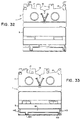
- Figure 32 shows a preferred base profile of the present invention.
- Figure 33 shows preferred dust door hinges of the present invention.
- a low cost video cassette is generally indicated by the numeral 1.
- the cassette has a base 3 and a cover 5.
- the cover surface is stepped upward from the base.
- a dust door 7 is integrally formed in a cover.
- Reel hub springs 9 are integrally formed in the cover, and locator pins 11 on stanchions 13 are also integrally formed in the cover.
- the recessed front walls 15 and 17, and the forward extensions 19 which support the tape-guiding surfaces 21.
- tap guide pins 23 and 25 which are mounted on forward-extending projections 27 and 29.
- the cover 5 has a rectangular opening 39.
- a lug 41 extends inward from the outer edge of the opening, and a spring 43 is integrally formed on a living hinge 45 connected to the lug.
- the spring has a dished shape, as generally shown in Figure 4.
- Flap 31 is hinged 38 along a longitudinal edge of the opening 39, and tabs 47 on the flaps engage complementary depressions in the walls to hold the flaps closed.
- a fulcrum bar 49 on flap 31 urges spring 43 toward a tape reel.
- Figure 5 shows the spring 43 in the opening 39 with the flap 31 and fulcrum 49 in edge elevation.
- Figure 6 shows an edge elevation of the spring 43, the flap 31 with the fulcrum 49, and the tabs 47.
- the tabs 47 fit in complementary openings in the wall.
- Figure 8 shows a hinged compound spring 51 with a flat portion 53 which underlies the flap 31, and a bent portion 55 which presses against a reel hub.
- Figures 3-6 and 8 show the molded position; Figure 7 shows the operating position of a flap and spring.
- Figure 9 is an alternate form of flap 31' and spring 51', which is integrally molded in profile on the cover.
- Figure 10 is a schematic cross-sectional representation of the flap 31' and spring 51' in closed position in the rectangular opening 39.
- Figure 11 shows the base of a standard cassette 53.
- a light source is inserted in cylindrical opening 55.
- Light beams 57 travel through windows in the outer walls 59 to impinge upon receivers when the light shines through clear leaders to indicate that the tape is near its end.
- the cassette of the present invention has a partial cylindrical wall 61 in the front wall 63, and has an open frontal portion which may permit light scatter from the light source 65.
- the open frontal portion of the cassette 1 is shown in Figure 15.
- the invention employs a partial or full cylinder with an opaque coating in the front wall, as shown in Figure 14.
- the cylinder 67 has a closed top and lateral holes 69 or covered channels, which screen all light from the source except the direct light in the defined direction 57.
- the invention uses opaque coatings 71, or snap-in opaque walls with clear window openings 73. Any opaque light-screening material may be used.
- the screening material is on a side panel 75.
- Figure 19 shows the supply side wall screen 75 with the window 73
- the Figure 20 shows the take-up side screen 77 with the clear window 73.
- the present invention uses an integral latch mechanism 79, as shown in Figures 21 and 22.
- a release recess 81 is formed with the side wall of the base.
- a top member 85 is cantilevered horizontally, and a living spring 87 joins a latch plate 89 to the cantilevered support 85.
- the latch plate carries a latch 91 and a latch release pad 93.
- a portion of the latch plate 89 or the hinge 87 extends laterally from the support 85.
- a dust door return arm 95 is vertically formed on the projecting part of the latch plate 89 or the hinge 87. A the dust door 7 returns to a closed position, the inside of the dust door presses on the upper edge 97 of return arm 95, causing plate 89 to pivot outwardly, carrying latch 91 into engagement with the vertical latching groove on the dust door.
- the low cost video cassette 1 of the present invention has a tension spring 99, which is connected at one end 101 to an inside of the cover 5, and which is connected at the other end 103 to an inside of a dust door 7.
- the spring 99 tends to return the dust door to a closed position.
- One or more hold-downs 105 hold the end portions of a spring parallel to the door.
- the spring is free to bend in the center 107, such as to return the spring to a normal, curved condition.
- the base 3 has integrally formed tape reel pockets 109, and integrally formed brake levers 111 with brake teeth 113 on one end.
- the brake levers are supported on fixed pivots 115, and operator ends 117 extend oppositely from the pivots so that spreading the operator ends 117 releases the brake teeth 113 from engagement with reel teeth.
- the dust door 7 may be closed by a coil spring 125 fixed in a coil spring pocket 127 on a side wall 129. Free end 131 of the coil spring rests in a J-hook 133 connected to the door 7 for urging the door 7 downward into a closed position.
- a leaf spring 135, a coil spring 137, or a straight wire spring 139 may be fixed in or molded into an appropriate receiver 141 in the hinge 143 or the downward-extending portions 145 and 147 of the door mount and door respectively.
- Figure 28 shows a side elevation of the dust door 7 mounting lug 145 and hinge 143.
- Figure 29 shows the brake operators or retractors 117, which extend through the wall thickness of the base 3.
- a retractor pin 151 extends only partially through the wall thickness into contact with the retractors to release the brake.
- Figures 30 and 31 show a frangible anti-record tab 33 in a record groove 37, which opens downwardly in base 3.
- Figure 31 shows the record tab 33 in its inverted molded position.
- the record tab 33 is parallel with the outer surface of the back wall 35 of the cassette.
- the base has a modified profile with recessed front walls 15 and 17 and projections 19 which support the tape guide walls, and projections 27 and 29 which support the tape guide roller pins.
- the preferred door hinges 143 are positioned at outward extremities of the door and are not positioned across the door.
- a shelf 161, which projects forward from the cover 5, has extensions 163 and 165 which have receivers for the tops of pins 23 and 25, which receive the tape guide rollers 119.
Landscapes
- Tape Measures (AREA)
- Packaging Of Annular Or Rod-Shaped Articles, Wearing Apparel, Cassettes, Or The Like (AREA)
- Automatic Tape Cassette Changers (AREA)
Claims (21)
- Eine Videokassette bestehend aus einer angeformten Bodenplatte (3), einer an der Bodenplatte befestigten und sich von der Bodenplatte aus nach oben erstreckenden Rückwand, einem mittels eines angeformten aktiven Gelenkes drehbar an die Rückwand angelenkten Deckel (5), ersten und zweiten dem Deckel angeformten Federn (43) zum Andrücken der Bandrollen gegen die Bodenplatte, gekennzeichnet durch sich nach unten, die gegenüberliegenden Seiten einer Vorderseite des Deckels dem aktiven Gelenk gegenüber entlang sich erstreckende Absatzteile (145, 147) und einen Staubschutzdeckel, der an weiteren an den unteren Enden der Absatzteile befindlichen aktiven Gelenke (143) befestigt ist, wobei die weiteren aktiven Gelenke nur an den sich gegenüberliegenden Endbereichen der Vorderseite des Deckels befestigt sind und nicht in der Mitte des Deckels.
- Das Gerät gemäss Patentanspruch 1 wobei der Deckel mit ersten und zweiten rechteckigen Öffnungen (39) versehen ist und wobei die Federn sich von Aussenseiten der Öffnungen aus nach innen erstrecken und wobei die Federn (43) an, von den Öffnungen aus nach unten hinausragenden, Ösen (41) angelenkt (45) sind.
- Das Gerät gemäss Patentanspruch 2, wobei der Deckel weiter eine Drehachse (49) enthält um in die Federn neben dem Federgelenk (45) einzugreifen.
- Das Gerät gemäss Patentanspruch 2, wobei die Feder (43) aus einer dreidimensional gekrümmten Feder besteht, die mit einem Ende mit dem Gelenk (45) verbunden ist und ein gebogenes Mittelteil hat und ein gegenüberliegendes freies Ende (55) um die Spule zu berühren aufweist.
- Das Gerät gemäss Patentanspruch 1, wobei die Feder (51') mit der Deckelklappe (31') verbunden ist und der Deckelklappe profiliert angeformt ist um nach unten einer Spule zugewandt in die Kassette hinauszuragen.
- Das Gerät gemäss Patentanspruch 1, wobei die Bodenplatte (3) einen ungefähr der Dicke der Bodenplatte entsprechenden Absatz aufweist und weiter mit der Bodenplatte verbundene einstückig geformte sich gegenseitig erstreckende Spulenverriegelungen (111) enthält, wobei die Spulenverriegelungen Betätigungsbereiche (117) aufweisen, die sich hinaus in den Absatz erstrecken, wobei die Spulenverriegelungsbetätigungen vom Betätiger innerhalb der Manteldicke bewegt werden.
- Das Gerät gemäss Patentanspruch 1, das ferner eine, durch ein aktives Gelenk (143) mit der von der Rückwand entfernten Deckelkante (5) verbundene Bandklappe (7), enthält und einen, einer nach oben gerichteten Verlängerung der Bodenplatte angeformten, Staubschutzdeckelriegel (89) und mittels eines aktiven Gelenkes hiermit verbunden zur Verriegelung einer Seite des Staubschutzdeckels um den Staubschutzdeckel in einem geschlossenem Stand zu halten, wobei der Riegel weiter einen, vom Riegel sich zum Staubschutzdeckel hin erstreckenden Rückführungsarm (95) enthält um den Staubschutzdeckel zu berühren, wenn der Staubschutzdeckel wieder in den geschlossenen Stand zurückgeführt wird und den Riegel auswärts zu drücken zu einer Verriegelungsberührung mit einem Innenkamm an einer Seite des Staubschutzdeckels.
- Das Gerät gemäss Patentanspruch 1, wobei der Staubschutzdeckel (7) seitlich in einem ersten Gelenk (143) drehbar ist zum wahlweisen Eingriff oder Nichteingriff mit dem Staubschutzdeckelkamm, wobei der Rückführungsarm (95) vom Riegel (89) aus nach innen mit Zwischenraum angeordnet ist, und wobei der Riegel (89) und der Rückführungsarm vom Gelenk (87) aus sich frei nach vorne erstrecken.
- Das Gerät gemäss Patentanspruch 1, wobei die Bodenplatte (3) und der Deckel (5) aus Klarsichtmaterial sind, und weiter eine mit dem vorderen Teil der Bodenplatte verbundene Lichtabschirmung (71) enthält um Bandleuchtsignale, abzuschirmen wenn der Videorecorder in Betrieb ist.
- Das Gerät gemäss Patentanspruch 9, wobei die Lichtabschirmung Beschichtungen (71) auf oder Pigmente in dem Klarsichtkassettenkörper enthält.
- Das Gerät gemäss Patentanspruch 10, wobei die Lichtabschirmung einen undurchsichtigen teilweisen Zylinder (67) mit geschlossener Oberseite und Löchern (69) oder abgedeckten Kanälen enthält, die alles ausser direktem Abtastlicht (57) in einer bestimmten Richtung zu Lichtquellenempfänger abschirmen.
- Das Gerät gemäss Patentanspruch 9, wobei die Kassette weiter einen undurchsichtigen Zylinder (67) mit geschlossener Oberseite und Löchern (69) oder abgedeckten Kanälen enthält, die alles ausser direktem Abtastlicht (57) in einer bestimmten Richtung zu Lichtquellenempfänger abschirmen.
- Das Gerät gemäss Patentanspruch 9, wobei die Abschirmungen erste und zweite Schirmwände (71) enthalten, die in das Mantelgehäuse eingeschnappt, eingepresst oder angeschweisst sind, und die Löcher (73) aufweisen, angeordnet um Direktlicht von einer Abtastlichtquelle zuzulassen, aber jedes andere Licht abzuschirmen.
- Das Gerät gemäss Patentanspruch 9, wobei die Lichtabschirmung (71) aus undurchsichtigen Abschirmaufklebern, Farben oder Pigmenten gewählt wird, die auf die Kassette angeordnet werden um Licht zu blockieren, ausgenommen Direktlicht von einer Lichtquelle, das durch ein Fenster (73) vor einem Abtastlichtempfänger hereinfällt.
- Das Gerät gemäss Patentanspruch 1, das weiter eine gerade, mit einem ersten Längsende an einem Staubschutzdeckel (7) befestigte Feder (99) enthält, und sich über einen Abstand innerhalb des Deckels (5) zur Rückwand hin erstreckt, mit einem zweiten unter dem Deckel (5) befestigten Ende (101) um sich den Deckel entlang zu erstrecken und zusammenzudrücken und zum Schliessen des Staubschutzdeckels zu dienen.
- Das Gerät gemäss Patentanspruch 1, das weiter eine in einer Aussparung der Bodenplatte (127) festgehaltene und mit dem Deckel verbundene Feder (125) enthält um den Staubschutzdeckel nach unten zu drücken.
- Das Gerät gemäss Patentanspruch 1, das weiter eine am Deckel befestigte Feder (99) enthält.
- Das Gerät gemäss Patentanspruch 1, weiter gekennzeichnet durch erste und zweite verlängerte, dem Deckel angeformte und eine Seite entlang am Deckel angelenkte, und gegenüberliegende Kanten entlang mit gegenüberliegende Deckelöffnungen befestigbare Klappen (31) um die Federn (43) abzudecken und die Federn zum Eingriff mit den Spulennaben hinunterzuzwingen.
- Das Gerät gemäss Patentanspruch 1, das weiter eine, der Bodenwand und der Rückwand angeformte und sich von einer Öffnung in der Bodenwand aus nach oben erstreckende Löschschutzlaschenaussparung (37) enthält, und eine der Rückwand angeformte und sich in die Löschschutzlaschenöffnung zu einer, der Bodenwand nähe, Position erstreckende Löschschutzlasche (33).
- Das Gerät gemäss Patentanspruch 1, wobei die Bodenplatte erste und zweite Bandführungen (21) enthält und eine, von der Vorderseite der Bodenplatte aus sich nach innen erstreckende Vorderwand (15), und im allgemeinen rechteckige, sich von der Vorderwand aus nach vorne erstreckende Vorsprünge (19) zur Bandführung.
- Das Gerät gemäss Patentanspruch 20, wobei die nach vorne gerichtete Vorsprünge (19) im allgemeinen rhombische Vorsprünge mit rechteckigen Vorderseiten und rechteckigen, sich von den Vorderseiten aus unweit der Vorderwandmitte (15, 17) angeordneten sich aufwärts erstreckenden Bandführungen (21) enthalten, und eine im allgemeinen dreieckige seitliche Verlängerung (27) mit einem angeformten sich nach oben erstreckenden Bandführungsstift (23) zur Aufnahme und Unterstützung einer Bandführungsrolle unweit eines Kantenbereiches der Vorderwand, einen im allgemeinen rechteckigen nach vorne gerichteten Vorsprung (29), der an einer seiner Ecken einen zweiten, von dort aus sich senkrecht nach oben erstreckenden Bandführungsstift (25) aufweist, zur Aufnahme einer zweiten Bandführungsrolle (119), und der einer seiner Seiten entlang eine Aussparung aufweist zur Aufnahme eines Staubschutzdeckelriegels (79).
Applications Claiming Priority (4)
| Application Number | Priority Date | Filing Date | Title |
|---|---|---|---|
| US07/639,516 US5114092A (en) | 1991-01-10 | 1991-01-10 | Low cost video cassette |
| US639516 | 1991-01-10 | ||
| PCT/US1992/000060 WO1992012517A1 (en) | 1991-01-10 | 1992-01-10 | Low cost video cassette |
| PCT/US1992/007842 WO1994009494A1 (en) | 1990-05-11 | 1992-10-20 | Welded video cassette |
Publications (3)
| Publication Number | Publication Date |
|---|---|
| EP0566664A1 EP0566664A1 (de) | 1993-10-27 |
| EP0566664A4 EP0566664A4 (de) | 1994-10-19 |
| EP0566664B1 true EP0566664B1 (de) | 1997-09-03 |
Family
ID=26785022
Family Applications (1)
| Application Number | Title | Priority Date | Filing Date |
|---|---|---|---|
| EP92904181A Expired - Lifetime EP0566664B1 (de) | 1991-01-10 | 1992-01-10 | Billige videokassette |
Country Status (11)
| Country | Link |
|---|---|
| US (2) | US5114092A (de) |
| EP (1) | EP0566664B1 (de) |
| JP (1) | JPH06508710A (de) |
| AT (1) | ATE157800T1 (de) |
| AU (1) | AU664983B2 (de) |
| CA (1) | CA2100095A1 (de) |
| DE (1) | DE69222026T2 (de) |
| DK (1) | DK0566664T3 (de) |
| ES (1) | ES2109342T3 (de) |
| GR (1) | GR3025513T3 (de) |
| WO (1) | WO1992012517A1 (de) |
Families Citing this family (19)
| Publication number | Priority date | Publication date | Assignee | Title |
|---|---|---|---|---|
| US5114092A (en) * | 1991-01-10 | 1992-05-19 | Paul J. Gelardi | Low cost video cassette |
| EP0665978A4 (de) * | 1990-05-11 | 1996-10-02 | Paul J Gelardi | Verfahren zum Vergleichen der Motormomenten für ein Mehrfach-Triebwerk-Flugzeug. |
| US5544834A (en) * | 1990-11-19 | 1996-08-13 | Wti International Corporation | Video tape cassette |
| US5264987A (en) * | 1991-06-14 | 1993-11-23 | U.S. Philips Corporation | Cassette for magnetic tape provided with window |
| JP2564572Y2 (ja) * | 1991-08-23 | 1998-03-09 | 富士写真フイルム株式会社 | 磁気テープカセット |
| US5308015A (en) * | 1992-05-21 | 1994-05-03 | Lcv Associates | Dust door arrangement for video cassettes |
| WO1993026008A1 (en) * | 1992-06-15 | 1993-12-23 | John Michael Woodbury | Video cassettes |
| US5272583A (en) * | 1992-06-19 | 1993-12-21 | Yerkes Craig H | Collapsible magnetic tape cassette |
| KR940004617A (ko) * | 1992-08-28 | 1994-03-15 | 최준식 | 테이프릴용 아답터 |
| US5482222A (en) * | 1993-01-07 | 1996-01-09 | V-Lite Corporation | Lightweight solid-core video cassette cartridge |
| US5398881A (en) * | 1993-01-07 | 1995-03-21 | V-Lite Corporation | Lightweight video cassette cartridge |
| CN1062967C (zh) * | 1995-03-21 | 2001-03-07 | 炜通有限公司 | 具有改进的磁带检测光路的磁带盒 |
| US5568899A (en) * | 1995-05-05 | 1996-10-29 | V-Lite Corporation | Lightweight video cassette cartridge |
| US5584440A (en) * | 1995-11-06 | 1996-12-17 | V-Lite Corporation | Lightweight video cassette cartridge |
| US6302344B1 (en) | 1999-07-01 | 2001-10-16 | Chen K. Su | Lightweight video cassette |
| JP2002093114A (ja) * | 2000-09-20 | 2002-03-29 | Victor Co Of Japan Ltd | テープカセット |
| US7127576B1 (en) * | 2003-05-21 | 2006-10-24 | Raytheon Company | Method and system for data duplication |
| JP5683952B2 (ja) * | 2007-08-07 | 2015-03-11 | ソルヴェイ・スペシャルティ・ポリマーズ・イタリー・エッセ・ピ・ア | 改質された炭素質材料及び炭素質材料の改質方法 |
| EP2100909A1 (de) | 2008-03-14 | 2009-09-16 | Solvay Solexis S.p.A. | (Per)fluor-Additionsprodukte |
Family Cites Families (53)
| Publication number | Priority date | Publication date | Assignee | Title |
|---|---|---|---|---|
| US3712559A (en) * | 1969-11-05 | 1973-01-23 | Information Terminals Corp | Tape cassette and improvements therefor |
| JPS5024754Y1 (de) * | 1970-08-10 | 1975-07-25 | ||
| US3900171A (en) * | 1972-06-29 | 1975-08-19 | Sony Corp | Tape cassette |
| US4004752A (en) * | 1973-02-01 | 1977-01-25 | Sony Corporation | Tape cassette |
| US3980255A (en) * | 1973-10-04 | 1976-09-14 | Sony Corporation | Tape cassette |
| JPS587510Y2 (ja) * | 1976-05-04 | 1983-02-09 | 松下電器産業株式会社 | テ−プカセツト |
| JPS5756381Y2 (de) * | 1977-07-22 | 1982-12-04 | ||
| JPS5728311Y2 (de) * | 1977-12-16 | 1982-06-21 | ||
| JPS54163621U (de) * | 1978-05-08 | 1979-11-16 | ||
| US4184594A (en) * | 1978-12-22 | 1980-01-22 | Hehn Bruce A | Video cassette storage container |
| DE2951951A1 (de) * | 1979-12-22 | 1981-07-09 | Basf Ag, 6700 Ludwigshafen | Bandkassette fuer streifen- oder bandfoermige aufzeichnungstraeger, insbesondere magnetbaender, sowie kassettengehaeuse und schutz-/haltehuelle fuer aufgewickelte aufzeichnungstraeger |
| US4249710A (en) * | 1980-03-19 | 1981-02-10 | Dobbs-Stanford | Reloadable cassette |
| US4367963A (en) * | 1980-07-21 | 1983-01-11 | Wordex | Refillable typewriter ribbon cartridge |
| JPS57123573A (en) * | 1981-01-20 | 1982-08-02 | Victor Co Of Japan Ltd | Adapter for tape cassette |
| US4485988A (en) * | 1981-11-04 | 1984-12-04 | Matsushita Electric Industrial Co., Ltd. | Tape cassette |
| US4683511A (en) * | 1981-11-30 | 1987-07-28 | Stephen Kara | Head and guide cleaning device for video tape recorder |
| DE3365072D1 (en) * | 1982-03-23 | 1986-09-11 | Matsushita Electric Industrial Co Ltd | Tape cassette |
| JPS59213072A (ja) * | 1983-05-17 | 1984-12-01 | Hitachi Maxell Ltd | テ−プカ−トリツジ |
| US4519521A (en) * | 1983-09-06 | 1985-05-28 | Matsushita Electric Industrial Co., Ltd. | Tape cassette |
| USRE32447E (en) * | 1984-01-06 | 1987-06-30 | Shape Inc. | Tape cassette with separate tape guide |
| KR900006314B1 (ko) * | 1984-01-25 | 1990-08-28 | 마쯔시다덴기산교 가부시기가이샤 | 테이프카세트 및 그것을 사용하는 카세트레코오더 |
| DE3580684D1 (de) * | 1984-02-16 | 1991-01-10 | Matsushita Electric Industrial Co Ltd | Bandkassette fuer kurzzeitige aufnahme. |
| DE3416481A1 (de) * | 1984-05-04 | 1985-11-07 | Agfa-Gevaert Ag, 5090 Leverkusen | Lichtkanalabdeckung fuer eine endabschaltvorrichtung eines kassettenmagnetbandes |
| DE8415333U1 (de) * | 1984-05-19 | 1984-11-22 | Basf Ag, 6700 Ludwigshafen | Magnetbandkassette, insbesondere kompaktkassette |
| DE8418178U1 (de) * | 1984-06-15 | 1985-01-03 | Basf Ag, 6700 Ludwigshafen | Bandkassette, insbesondere video-magnetbandkassette mit mindestens einer andruckfeder |
| JPS6173290A (ja) * | 1984-09-17 | 1986-04-15 | Sony Corp | テ−プカセツト |
| DE3441156A1 (de) * | 1984-11-10 | 1986-05-15 | Agfa-Gevaert Ag, 5090 Leverkusen | Frontklappenverriegelung von magnetbandkassetten, insbesondere videobandkassetten |
| US4763218A (en) * | 1985-03-18 | 1988-08-09 | Westfall Wade H | Video tape cassette with internal tape erasing means |
| US4700320A (en) * | 1985-07-09 | 1987-10-13 | American Telephone And Telegraph Company, At&T Bell Laboratories | Bitmapped graphics workstation |
| US4662579A (en) * | 1985-08-16 | 1987-05-05 | Shape Inc. | Coined reel leaf spring for a video tape cassette |
| US4678080A (en) * | 1985-12-03 | 1987-07-07 | Minnesota Mining And Manufacturing Company | Videocassette sleeve and cover |
| JPH0740397B2 (ja) * | 1986-04-11 | 1995-05-01 | 松下電器産業株式会社 | 磁気記録再生装置 |
| JP2604718B2 (ja) * | 1986-04-11 | 1997-04-30 | 松下電器産業株式会社 | テープカセツト |
| DE3788637T2 (de) * | 1986-07-18 | 1994-04-28 | Matsushita Electric Ind Co Ltd | Bandkassette. |
| WO1988002916A1 (en) * | 1986-10-20 | 1988-04-21 | John Michael Woodbury | Video cassettes |
| US4802048A (en) * | 1986-10-31 | 1989-01-31 | David H. Rubenstein | Limited play tape cassette system |
| US4793570A (en) * | 1987-01-06 | 1988-12-27 | Shape Inc. | Tape cassette with separate tape guide having integrated rollers and methods for manufacturing same |
| AU1383988A (en) * | 1987-03-30 | 1988-09-29 | Williamson, K.L. | Disposable non-rewinding tape cassette |
| US4912731A (en) * | 1987-04-13 | 1990-03-27 | Vittorio Nardi | Plasma focus apparatus with field distortion elements |
| WO1988008196A1 (en) * | 1987-04-13 | 1988-10-20 | John Michael Woodbury | Video cassettes |
| US4899242A (en) * | 1987-07-09 | 1990-02-06 | Tdk Corporation | Locking mechanism of magnetic tape cassette |
| JPH0743827Y2 (ja) * | 1987-12-29 | 1995-10-09 | ソニー株式会社 | テープカセット |
| US4848698A (en) * | 1988-06-02 | 1989-07-18 | Newell Research Corporation | Method for writing and means for reading position-indicating markers on tape |
| US4842217A (en) * | 1988-08-22 | 1989-06-27 | Vinson David A | Self destruct video tape cassette |
| JPH02177069A (ja) * | 1988-09-13 | 1990-07-10 | Sony Corp | テープカセット |
| US4906772A (en) * | 1988-12-02 | 1990-03-06 | Amoco Corporation | Process for production of polycarboxylic aromatic acids |
| US5084799A (en) * | 1988-12-06 | 1992-01-28 | Skc Limited | Lid locking device for tape cassette |
| JPH02223083A (ja) * | 1989-02-23 | 1990-09-05 | Sony Corp | テープカセット |
| US4883176A (en) * | 1989-05-15 | 1989-11-28 | Container Corporation Of America | Paperboard video cassette housing |
| US5056735A (en) * | 1989-08-04 | 1991-10-15 | Shape Inc. | Video cassette integral actuator/reel lock/spring |
| CN1018305B (zh) * | 1989-09-11 | 1992-09-16 | 张黎 | 壳式磁带系统 |
| US4969612A (en) * | 1989-12-04 | 1990-11-13 | Thomas Robert G | Cassette formed from a bendable material |
| US5114092A (en) * | 1991-01-10 | 1992-05-19 | Paul J. Gelardi | Low cost video cassette |
-
1991
- 1991-01-10 US US07/639,516 patent/US5114092A/en not_active Expired - Fee Related
-
1992
- 1992-01-10 DE DE69222026T patent/DE69222026T2/de not_active Expired - Fee Related
- 1992-01-10 ES ES92904181T patent/ES2109342T3/es not_active Expired - Lifetime
- 1992-01-10 DK DK92904181.2T patent/DK0566664T3/da active
- 1992-01-10 JP JP4504449A patent/JPH06508710A/ja active Pending
- 1992-01-10 AU AU11998/92A patent/AU664983B2/en not_active Ceased
- 1992-01-10 CA CA002100095A patent/CA2100095A1/en not_active Abandoned
- 1992-01-10 AT AT92904181T patent/ATE157800T1/de not_active IP Right Cessation
- 1992-01-10 WO PCT/US1992/000060 patent/WO1992012517A1/en not_active Ceased
- 1992-01-10 EP EP92904181A patent/EP0566664B1/de not_active Expired - Lifetime
- 1992-03-09 US US07/848,046 patent/US5390871A/en not_active Expired - Fee Related
-
1997
- 1997-11-26 GR GR970403162T patent/GR3025513T3/el unknown
Also Published As
| Publication number | Publication date |
|---|---|
| US5390871A (en) | 1995-02-21 |
| DE69222026T2 (de) | 1998-05-14 |
| AU1199892A (en) | 1992-08-17 |
| CA2100095A1 (en) | 1992-07-23 |
| JPH06508710A (ja) | 1994-09-29 |
| ATE157800T1 (de) | 1997-09-15 |
| EP0566664A1 (de) | 1993-10-27 |
| AU664983B2 (en) | 1995-12-14 |
| GR3025513T3 (en) | 1998-02-27 |
| DK0566664T3 (da) | 1998-04-14 |
| ES2109342T3 (es) | 1998-01-16 |
| US5114092A (en) | 1992-05-19 |
| WO1992012517A1 (en) | 1992-07-23 |
| EP0566664A4 (de) | 1994-10-19 |
| DE69222026D1 (de) | 1997-10-09 |
Similar Documents
| Publication | Publication Date | Title |
|---|---|---|
| US5114092A (en) | Low cost video cassette | |
| US4460930A (en) | Erroneous erasure preventing apparatus | |
| CA1244128A (en) | Shuttering mechanism for a cassette | |
| JPH0620914B2 (ja) | 磁気テープ・カセットのための容器 | |
| GB2102386A (en) | Protecting tape in tape cassettes | |
| US5596464A (en) | Locking assembly for a lid member of a tape cassette | |
| JPH03242887A (ja) | テープカセット | |
| CA2097793A1 (en) | Shutter-type tape cassette | |
| US5308015A (en) | Dust door arrangement for video cassettes | |
| JPH0513356B2 (de) | ||
| US5299755A (en) | Lid locking mechanism for a tape cassette | |
| JP3503327B2 (ja) | テープカートリッジ | |
| JPH0789431B2 (ja) | ディスクカセット装置 | |
| US5335875A (en) | Tape cassette structure | |
| JPS60136079A (ja) | テ−プカ−トリツジ | |
| JP2552448B2 (ja) | テ−プカ−トリツジ | |
| JP3550857B2 (ja) | テープカートリッジ | |
| JPS6349909Y2 (de) | ||
| JPS6020222Y2 (ja) | 磁気テ−プカ−トリツジ | |
| JPS6112627Y2 (de) | ||
| JPH0413799Y2 (de) | ||
| JPH04248178A (ja) | テープカセット | |
| WO1997008698A1 (fr) | Appareil a support d'enregistrement equipe d'un mecanisme empechant tout enregistrement errone | |
| EP1168336A2 (de) | Magnetbandkassette | |
| JPH06267229A (ja) | テープカセット |
Legal Events
| Date | Code | Title | Description |
|---|---|---|---|
| PUAI | Public reference made under article 153(3) epc to a published international application that has entered the european phase |
Free format text: ORIGINAL CODE: 0009012 |
|
| 17P | Request for examination filed |
Effective date: 19930730 |
|
| AK | Designated contracting states |
Kind code of ref document: A1 Designated state(s): AT BE CH DE DK ES FR GB GR IT LI LU MC NL SE |
|
| RAP1 | Party data changed (applicant data changed or rights of an application transferred) |
Owner name: CAPOTOSTO, DAVID A. Owner name: GELARDI, JOHN A. Owner name: L.C.V. ASSOCIATES |
|
| RAP1 | Party data changed (applicant data changed or rights of an application transferred) |
Owner name: L.C.V. ASSOCIATES |
|
| A4 | Supplementary search report drawn up and despatched | ||
| AK | Designated contracting states |
Kind code of ref document: A4 Designated state(s): AT BE CH DE DK ES FR GB GR IT LI LU MC NL SE |
|
| 17Q | First examination report despatched |
Effective date: 19960115 |
|
| GRAG | Despatch of communication of intention to grant |
Free format text: ORIGINAL CODE: EPIDOS AGRA |
|
| GRAH | Despatch of communication of intention to grant a patent |
Free format text: ORIGINAL CODE: EPIDOS IGRA |
|
| GRAH | Despatch of communication of intention to grant a patent |
Free format text: ORIGINAL CODE: EPIDOS IGRA |
|
| GRAA | (expected) grant |
Free format text: ORIGINAL CODE: 0009210 |
|
| AK | Designated contracting states |
Kind code of ref document: B1 Designated state(s): AT BE CH DE DK ES FR GB GR IT LI LU MC NL SE |
|
| REF | Corresponds to: |
Ref document number: 157800 Country of ref document: AT Date of ref document: 19970915 Kind code of ref document: T |
|
| REG | Reference to a national code |
Ref country code: CH Ref legal event code: EP |
|
| REF | Corresponds to: |
Ref document number: 69222026 Country of ref document: DE Date of ref document: 19971009 |
|
| ITF | It: translation for a ep patent filed | ||
| RAP2 | Party data changed (patent owner data changed or rights of a patent transferred) |
Owner name: L.C.V. ASSOCIATES |
|
| ET | Fr: translation filed | ||
| BECA | Be: change of holder's address |
Free format text: 970903 *L.C.V. ASSOCIATES:P.O. BOX 488, KENNEBUNKPORT MAINE 04043-0488 |
|
| REG | Reference to a national code |
Ref country code: CH Ref legal event code: NV Representative=s name: PATENTANWALTSBUERO FELDMANN AG |
|
| REG | Reference to a national code |
Ref country code: ES Ref legal event code: FG2A Ref document number: 2109342 Country of ref document: ES Kind code of ref document: T3 |
|
| REG | Reference to a national code |
Ref country code: GR Ref legal event code: FG4A Free format text: 3025513 |
|
| NLT2 | Nl: modifications (of names), taken from the european patent patent bulletin |
Owner name: L.C.V. ASSOCIATES |
|
| REG | Reference to a national code |
Ref country code: DK Ref legal event code: T3 |
|
| PLBE | No opposition filed within time limit |
Free format text: ORIGINAL CODE: 0009261 |
|
| STAA | Information on the status of an ep patent application or granted ep patent |
Free format text: STATUS: NO OPPOSITION FILED WITHIN TIME LIMIT |
|
| PG25 | Lapsed in a contracting state [announced via postgrant information from national office to epo] |
Ref country code: MC Free format text: LAPSE BECAUSE OF NON-PAYMENT OF DUE FEES Effective date: 19980731 |
|
| 26N | No opposition filed | ||
| PGFP | Annual fee paid to national office [announced via postgrant information from national office to epo] |
Ref country code: LU Payment date: 19981229 Year of fee payment: 8 |
|
| PGFP | Annual fee paid to national office [announced via postgrant information from national office to epo] |
Ref country code: GB Payment date: 19990107 Year of fee payment: 8 |
|
| PGFP | Annual fee paid to national office [announced via postgrant information from national office to epo] |
Ref country code: DK Payment date: 19990111 Year of fee payment: 8 |
|
| PGFP | Annual fee paid to national office [announced via postgrant information from national office to epo] |
Ref country code: GR Payment date: 19990113 Year of fee payment: 8 |
|
| PGFP | Annual fee paid to national office [announced via postgrant information from national office to epo] |
Ref country code: SE Payment date: 19990118 Year of fee payment: 8 |
|
| PGFP | Annual fee paid to national office [announced via postgrant information from national office to epo] |
Ref country code: NL Payment date: 19990119 Year of fee payment: 8 |
|
| PGFP | Annual fee paid to national office [announced via postgrant information from national office to epo] |
Ref country code: AT Payment date: 19990126 Year of fee payment: 8 |
|
| PGFP | Annual fee paid to national office [announced via postgrant information from national office to epo] |
Ref country code: FR Payment date: 19990127 Year of fee payment: 8 |
|
| PGFP | Annual fee paid to national office [announced via postgrant information from national office to epo] |
Ref country code: ES Payment date: 19990129 Year of fee payment: 8 |
|
| PGFP | Annual fee paid to national office [announced via postgrant information from national office to epo] |
Ref country code: BE Payment date: 19990201 Year of fee payment: 8 |
|
| PGFP | Annual fee paid to national office [announced via postgrant information from national office to epo] |
Ref country code: DE Payment date: 19990323 Year of fee payment: 8 |
|
| PGFP | Annual fee paid to national office [announced via postgrant information from national office to epo] |
Ref country code: CH Payment date: 19990428 Year of fee payment: 8 |
|
| PG25 | Lapsed in a contracting state [announced via postgrant information from national office to epo] |
Ref country code: LU Free format text: LAPSE BECAUSE OF NON-PAYMENT OF DUE FEES Effective date: 20000110 Ref country code: GB Free format text: LAPSE BECAUSE OF NON-PAYMENT OF DUE FEES Effective date: 20000110 Ref country code: DK Free format text: LAPSE BECAUSE OF NON-PAYMENT OF DUE FEES Effective date: 20000110 Ref country code: AT Free format text: LAPSE BECAUSE OF NON-PAYMENT OF DUE FEES Effective date: 20000110 |
|
| PG25 | Lapsed in a contracting state [announced via postgrant information from national office to epo] |
Ref country code: SE Free format text: LAPSE BECAUSE OF NON-PAYMENT OF DUE FEES Effective date: 20000111 Ref country code: ES Free format text: LAPSE BECAUSE OF NON-PAYMENT OF DUE FEES Effective date: 20000111 |
|
| PG25 | Lapsed in a contracting state [announced via postgrant information from national office to epo] |
Ref country code: LI Free format text: LAPSE BECAUSE OF NON-PAYMENT OF DUE FEES Effective date: 20000131 Ref country code: GR Free format text: LAPSE BECAUSE OF NON-PAYMENT OF DUE FEES Effective date: 20000131 Ref country code: CH Free format text: LAPSE BECAUSE OF NON-PAYMENT OF DUE FEES Effective date: 20000131 Ref country code: BE Free format text: LAPSE BECAUSE OF NON-PAYMENT OF DUE FEES Effective date: 20000131 |
|
| BERE | Be: lapsed |
Owner name: L.C.V. ASSOCIATES Effective date: 20000131 |
|
| PG25 | Lapsed in a contracting state [announced via postgrant information from national office to epo] |
Ref country code: NL Free format text: LAPSE BECAUSE OF NON-PAYMENT OF DUE FEES Effective date: 20000801 |
|
| GBPC | Gb: european patent ceased through non-payment of renewal fee |
Effective date: 20000110 |
|
| EUG | Se: european patent has lapsed |
Ref document number: 92904181.2 |
|
| REG | Reference to a national code |
Ref country code: CH Ref legal event code: PL |
|
| PG25 | Lapsed in a contracting state [announced via postgrant information from national office to epo] |
Ref country code: FR Free format text: LAPSE BECAUSE OF NON-PAYMENT OF DUE FEES Effective date: 20000929 |
|
| NLV4 | Nl: lapsed or anulled due to non-payment of the annual fee |
Effective date: 20000801 |
|
| REG | Reference to a national code |
Ref country code: DK Ref legal event code: EBP |
|
| PG25 | Lapsed in a contracting state [announced via postgrant information from national office to epo] |
Ref country code: DE Free format text: LAPSE BECAUSE OF NON-PAYMENT OF DUE FEES Effective date: 20001101 |
|
| REG | Reference to a national code |
Ref country code: FR Ref legal event code: ST |
|
| REG | Reference to a national code |
Ref country code: ES Ref legal event code: FD2A Effective date: 20010910 |
|
| PG25 | Lapsed in a contracting state [announced via postgrant information from national office to epo] |
Ref country code: IT Free format text: LAPSE BECAUSE OF NON-PAYMENT OF DUE FEES Effective date: 20050110 |