EP0567177A1 - Méthode de contrôle de traction pour automobile - Google Patents
Méthode de contrôle de traction pour automobile Download PDFInfo
- Publication number
- EP0567177A1 EP0567177A1 EP93200887A EP93200887A EP0567177A1 EP 0567177 A1 EP0567177 A1 EP 0567177A1 EP 93200887 A EP93200887 A EP 93200887A EP 93200887 A EP93200887 A EP 93200887A EP 0567177 A1 EP0567177 A1 EP 0567177A1
- Authority
- EP
- European Patent Office
- Prior art keywords
- engine
- engine torque
- reduction
- cylinders
- fuel
- Prior art date
- Legal status (The legal status is an assumption and is not a legal conclusion. Google has not performed a legal analysis and makes no representation as to the accuracy of the status listed.)
- Withdrawn
Links
Images



Classifications
-
- F—MECHANICAL ENGINEERING; LIGHTING; HEATING; WEAPONS; BLASTING
- F02—COMBUSTION ENGINES; HOT-GAS OR COMBUSTION-PRODUCT ENGINE PLANTS
- F02B—INTERNAL-COMBUSTION PISTON ENGINES; COMBUSTION ENGINES IN GENERAL
- F02B75/00—Other engines
- F02B75/16—Engines characterised by number of cylinders, e.g. single-cylinder engines
-
- B—PERFORMING OPERATIONS; TRANSPORTING
- B60—VEHICLES IN GENERAL
- B60K—ARRANGEMENT OR MOUNTING OF PROPULSION UNITS OR OF TRANSMISSIONS IN VEHICLES; ARRANGEMENT OR MOUNTING OF PLURAL DIVERSE PRIME-MOVERS IN VEHICLES; AUXILIARY DRIVES FOR VEHICLES; INSTRUMENTATION OR DASHBOARDS FOR VEHICLES; ARRANGEMENTS IN CONNECTION WITH COOLING, AIR INTAKE, GAS EXHAUST OR FUEL SUPPLY OF PROPULSION UNITS IN VEHICLES
- B60K28/00—Safety devices for propulsion-unit control, specially adapted for, or arranged in, vehicles, e.g. preventing fuel supply or ignition in the event of potentially dangerous conditions
- B60K28/10—Safety devices for propulsion-unit control, specially adapted for, or arranged in, vehicles, e.g. preventing fuel supply or ignition in the event of potentially dangerous conditions responsive to conditions relating to the vehicle
- B60K28/16—Safety devices for propulsion-unit control, specially adapted for, or arranged in, vehicles, e.g. preventing fuel supply or ignition in the event of potentially dangerous conditions responsive to conditions relating to the vehicle responsive to, or preventing, spinning or skidding of wheels
-
- B—PERFORMING OPERATIONS; TRANSPORTING
- B60—VEHICLES IN GENERAL
- B60T—VEHICLE BRAKE CONTROL SYSTEMS OR PARTS THEREOF; BRAKE CONTROL SYSTEMS OR PARTS THEREOF, IN GENERAL; ARRANGEMENT OF BRAKING ELEMENTS ON VEHICLES IN GENERAL; PORTABLE DEVICES FOR PREVENTING UNWANTED MOVEMENT OF VEHICLES; VEHICLE MODIFICATIONS TO FACILITATE COOLING OF BRAKES
- B60T8/00—Arrangements for adjusting wheel-braking force to meet varying vehicular or ground-surface conditions, e.g. limiting or varying distribution of braking force
- B60T8/17—Using electrical or electronic regulation means to control braking
- B60T8/175—Brake regulation specially adapted to prevent excessive wheel spin during vehicle acceleration, e.g. for traction control
-
- F—MECHANICAL ENGINEERING; LIGHTING; HEATING; WEAPONS; BLASTING
- F02—COMBUSTION ENGINES; HOT-GAS OR COMBUSTION-PRODUCT ENGINE PLANTS
- F02D—CONTROLLING COMBUSTION ENGINES
- F02D37/00—Non-electrical conjoint control of two or more functions of engines, not otherwise provided for
-
- F—MECHANICAL ENGINEERING; LIGHTING; HEATING; WEAPONS; BLASTING
- F02—COMBUSTION ENGINES; HOT-GAS OR COMBUSTION-PRODUCT ENGINE PLANTS
- F02B—INTERNAL-COMBUSTION PISTON ENGINES; COMBUSTION ENGINES IN GENERAL
- F02B75/00—Other engines
- F02B75/02—Engines characterised by their cycles, e.g. six-stroke
- F02B2075/022—Engines characterised by their cycles, e.g. six-stroke having less than six strokes per cycle
- F02B2075/027—Engines characterised by their cycles, e.g. six-stroke having less than six strokes per cycle four
Definitions
- This invention relates to a method of traction control for a vehicle.
- each cylinder disabled represents a relatively large reduction in the torque output of the engine.
- the first cylinder disabled usually produces the greatest power loss.
- the torque reduction provided by disabling one of the engine cylinders in response to a sensed excessive acceleration spin condition may be greater than the torque reduction necessary for control of the acceleration spin, thereby resulting in less than optimum acceleration performance of the vehicle.
- the large shift in power as the first cylinder is disabled may result in a perceived sag in the vehicle performance. Accordingly, it would be desirable to provide for a torque reduction level that is less than the torque reduction resulting from disabling one cylinder of the engine to accommodate acceleration conditions, such as a dry road launch, requiring a smaller torque reduction to arrest the excessive acceleration spin condition.
- the amount of the torque reduction associated with disabling one cylinder of the engine may be reduced by creating "half" cylinder increments by disabling a given cylinder such as on every other engine cycle or even every third engine cycle.
- this approach may produce rough engine operation due to the cylinder toggling on and off. It would be more desirable and result in smoother engine operation if the number of cylinders enabled during the traction control cycle remains constant or changes gradually.
- An example of the prior art is disclosed in US-A-5,025,881.
- a method in accordance with the present invention is characterised by the features specified in Claim 1.
- the torque reduction of the internal combustion engine in response to an excessive spin condition is provided by a combination of disabling selected engine cylinders and spark retard.
- the first level of torque reduction is provided at a level less than the torque reduction resulting from disabling a single cylinder of the engine by retarding the spark timing of the spark ignition in the cylinders.
- the amount of the retard of spark timing is such that the resulting torque reduction is less than the torque reduction resulting from disabling a single cylinder of the engine.
- spark timing control By incorporating the smaller first torque reduction step via spark retard, when the amount of engine torque reduction required to control acceleration spin condition is less than the torque reduction resulting from the disabling of a single cylinder, such as may occur during vehicle launch on a dry road, traction control is provided solely by spark timing control. Control is thereby provided at a lower torque reduction level thereby improving acceleration performance and ride quality. Further, since spark timing control responds faster than disabling a cylinder to reduce engine torque output, the response time of the system improves.
- the spark retard amount for traction control is varied as a predetermined function of engine speed.
- each cylinder is provided fuel via a respective one of eight fuel injectors INJ1-INJ8.
- This form of fuel delivery system is commonly referred to as a port fuel injection system.
- Each cylinder has associated therewith a respective one of eight spark plugs SP1-SP8 for igniting an air and fuel mixture in the cylinder.
- Air is drawn into the intake manifold of the engine 10 via an intake throttle bore in a throttle body 12 having an operator controlled throttle therein for regulating air flow into the engine 10.
- Air and the fuel provided by an injector for a cylinder is drawn into the cylinder and ignited at a predetermined time in relation to the engine cycle via the cylinder spark plug to develop driving torque delivered to the driven wheels of the vehicle.
- the combustion gases from the cylinders are then discharged into an exhaust conduit 14 which includes a conventional three-way catalytic converter 16 and then to the atmosphere.
- the engine 10 is controlled by a conventional (digital computer based) engine controller 18. Included in this control is the conventional control of the individual fuel injectors INJ1-INJ8 for injecting fuel to each of the respective cylinders of the engine 10 in timed relation to engine rotation.
- the injectors are controlled in response to various engine and vehicle operating parameters to achieve a scheduled air/fuel ratio. These parameters may include engine coolant temperature TEMP, manifold absolute pressure MAP, throttle position T.P., engine speed RPM, vehicle speed SPD and the output O2 of an exhaust oxygen sensor each being provided by a conventional transducer.
- the engine controller 18 further provides conventional control of ignition timing by control of spark timing signals provided to the spark plugs SP1-SP8 in timed relation to engine rotation.
- spark timing signals provided to the spark plugs SP1-SP8 in timed relation to engine rotation.
- the desired timing of spark ignition is established relative to the top dead centre crank position for each of the engine cylinders.
- Initiation of ignition is typically desired prior to the top dead centre position and ignition timing is calibrated in terms of engine crank angle degrees before top dead centre.
- the spark timing of the engine 10 is calibrated as close as possible to the MBT setting for maximizing engine output torque without causing pre-ignition or detonation.
- the result is a three-dimensional electronic lookup table in which the calibration timing values are stored as a function of engine speed and manifold absolute pressure.
- this invention provides for retarding the spark to provide engine torque reduction in response to an excessive acceleration spin condition by an amount that is less than the torque reduction provided by disabling one of the fuel injectors INJ1-INJ8.
- the engine controller 18 is digital computer based and takes the form of any well known digital computer controller used in present vehicles.
- controllers typically include a central processing unit, random access memory, read only memory, input/output circuits, timer circuits, analogue-to-digital converter and a clock.
- the central processing unit in the controller 18 executes an operating program permanently stored in its read only memory which also contains calibration constants and values stored such as in lookup tables addressed in accordance with the values of selected parameters.
- the various control functions including the control of the fuel injectors INJ1-INJ8 for establishing a desired air/fuel ratio and for limiting the engine torque output for traction control is provided as well as the control of the spark ignition timing via the spark plugs SP1/SP8 for igniting the mixture drawn into the cylinders of the engine 10 and further in accordance with the principles of this invention for reducing the engine torque output for traction control.
- traction control may be provided solely via engine torque control in response to the acceleration spin condition of the vehicle driven wheels.
- the engine controller 18 may further receive inputs from wheel speed sensors monitoring the speeds of the driven and undriven wheels of the vehicle. In response to these speed signals, the engine controller 18 executes a traction control routine which determines an excessive spin condition such as represented by wheel slip or rate of change in wheel slip and provides for control as hereinafter described in accordance with this invention to limit the wheel spin.
- the traction control is provided by both control of the brakes of the driven wheels and the engine torque output.
- the control of the driven wheel brakes is provided by a conventional brake traction control system that includes a brake traction control computer 20 that responds to the speeds of the vehicle driven wheels via speed sensors 22 and the speeds of the undriven wheels provided by wheel speed sensors 24.
- the brake traction control computer 20 actuates the driven wheel brakes 26 via a brake pressure actuator 28 to limit wheel spin when the speeds of the respective wheel speed sensors 22 and 24 represent an excessive acceleration spin condition in response to the application of excessive torque to the driven wheels via the internal combustion engine 10.
- the brake traction control computer 20 may take any conventional form including a general purpose digital computer such as the controller 18.
- the brake pressure actuator 28 may also take any conventional form and may include, for example, a DC torque motor responding to a signal output of the brake traction control computer 20 for controlling a piston establishing a controlled hydraulic pressure in the wheel brakes 26.
- While operation of the driven wheel brakes 26 may operate to limit wheel spin, it is undesirable to continuously apply large amounts of braking pressure to the driven wheels and further it may be desirable to provide for traction control solely by engine torque management when the amount of torque required to arrest an excessive spin condition may be achieved solely by engine torque reduction. For example, long periods of brake application for limiting wheel spin during conditions of high engine torque output may result in the brakes heating to unacceptable levels. In order to prevent this condition, the engine torque output is decreased by an amount established by the brake traction control computer 20 in accordance with this invention by retarding the spark timing and further as required by selectively disabling the engine cylinders.
- the brake traction control computer 20 determines and requests an amount of required engine torque in terms of the percent of maximum possible engine torque.
- This torque level request provided to the engine controller 18 is in the form of a constant frequency variable pulse width signal in which the pulse width (and therefore the duty cycle of the pulse width signal) directly represents the desired percent of maximum possible engine torque.
- the duty cycle representing the desired percent of maximum possible engine torque output is determined as a predetermined function of the measured slip of the driven wheels and the rate of change of slip of the driven wheels.
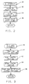
- the control of engine torque to achieve the percent of maximum possible engine torque requested by the brake traction control computer 20 is illustrated in the Figures 2-4.
- the engine controller 18 may execute a plurality of interrupt routines in response to various interrupt signals. In the control of the ignition timing and the fuel injectors, two such interrupt routines are executed.
- One such routine used in the control of engine torque for traction control is an event driven interrupt routine responsive to the trailing edge of each of the pulses of the duty cycle pulse width modulated signals from the computer 20.
- This duty cycle pulse interrupt routine is illustrated in Figure 2 and provides for a determination of the duration of the pulse width provided by the computer 20 representing the requested percentage of maximum torque of the engine 10.
- a second interrupt routine executed by the controller 18 is a time driven interrupt at a high frequency provided at, for example, 12.5 millisecond intervals. This 12.5 millisecond interrupt routine is illustrated in Figure 3.
- the interrupt executed with each falling edge of the duty cycle signal provided by the brake traction control computer 20 is executed to determine the pulse width of the pulse of the duty cycle signal.
- the duty cycle represented by this pulse width represents the engine torque level request in terms of the percent of maximum possible engine torque.
- the routine is entered at point 30 and proceeds to a step 32 wherein the width of the just ended duty cycle pulse is stored in memory.
- This pulse width is comprised of a count in a timer register clocked by the system clock.
- the duty cycle interrupt flag is cleared and at step 36, the pulse width timer register is cleared.
- the timer register is an element of a conventional input timer in the engine controller 18 in which the timer counts the system clock pulses during the high state of the pulse output of the brake traction control computer 20.
- the pulse output of the brake traction control computer 20 functions as an enabling signal to a gate for transmitting clock pulses to the clock input of the timer register.
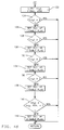
- the 12.5 millisecond interrupt routine which directs the operation of a number of subroutines for performing various tasks is illustrated.
- This routine is entered at point 38 and proceeds to execute a traction control routine at step 40 to establish the number of cylinders to be disabled and the spark retard required for traction control.
- This routine will be described in detail in Figures 4a, 4b and 4c.
- the routine executes a conventional fuel control routine at step 42 for controlling the injectors INJ1-INJ8 to provide for a scheduled air/fuel ratio of the mixture drawn into the respective cylinders.
- the injectors INJ1-INJ8 may be selectively disabled by the routine of step 40 to inhibit delivery of fuel independent of the fuel amount otherwise determined at step 42 for the individual fuel injectors.
- a spark control routine is next executed at step 44 for establishing the ignition timing in the individual cylinders of the engine 10.
- this routine establishes the ignition timing as close as possible to the MBT setting for maximum engine output torque.
- this ignition timing value is obtained from a three dimensional electronic lookup table in memory in which the timing values are stored as a function of engine speed, and manifold absolute pressure.
- the spark control routine 44 further adjusts the calibration spark timing value according to the engine operating condition in accordance with the spark retard established by the traction control routine 40 as will be described. Accordingly, the spark control routine 44 establishes a spark timing value for maximum output torque when traction control is not functioning and provides for retarding the spark timing value in accordance with the traction control routine 40 to decrease the engine torque output for traction control.
- the engine controller 18 may include as a separate element thereof an electronic spark timing unit to initiate combustion in the various engine cylinders via the spark plugs SP1-SP8 in accordance with the spark timing value established by the spark control routine 44.
- routines may be executed by the interrupt routine of Figure 3 to perform other engine/vehicle control functions. These routines are generally depicted at step 46 and may include, for example, control of the vehicle transmission.
- the traction control routine 40 of Figure 3 is illustrated in detail.
- This routine is entered at point 48 and proceeds to step 50 at which the instantaneous value dcTQ of the requested percent of maximum possible engine torque represented by the duty cycle of the signal provided by the brake traction control computer 20 is computed.
- the duty cycle value is computed based upon the known repetition frequency of the pulse output of the brake traction control computer 20 and the duty cycle pulse width stored at step 32 of the duty cycle interrupt routine of Figure 2. For example, if the value stored at step 32 of Figure 2 is representative of a pulse width of 8 milliseconds and the repetition frequency of the duty cycle signal from the brake traction control computer is 10 milliseconds, the requested percent of maximum possible engine output torque dcTQ determined at step 50 would be 80%.
- the routine next determines whether or not to control the engine torque based upon (A) the instantaneous value dcTQ of the requested percent of maximum possible torque to provide substantially instantaneous engine torque control or (B) a filtered value dcfTQ of the requested percent of maximum possible engine torque. For example, there is a delay associated with pressurizing the brakes in response to a sensed excessive wheel spin condition so that it may be desirable to instantaneously reduce engine torque when the brake traction control computer 20 first senses an excessive spin condition while the brakes are being applied. It also may be desirable to instantaneously increase the engine torque in response to an increase in the requested percent of maximum engine torque when the throttle is closed.
- step 52 determines whether or not a traction control active flag is set
- step 54 determines whether an initial shutoff time-out value is equal to zero
- step 56 determines whether or not the throttle of the engine 10 is closed such as represented by a closed throttle switch.
- a time in traction count t1 is set to zero at a step 58 after which the filtered value dcfTQ of the requested percent of maximum torque is set equal to the instantaneous value dcTQ of the requested percent of maximum torque at step 60. Therefore, as long as the foregoing conditions do not change, the value of dcfTQ tracks the instantaneous value dcTQ.
- step 52 determines the traction control active flag is set indicating engine torque is being controlled in response to a request from the brake traction control computer 20, and step 54 determines the initial shutoff time-out is equal to zero, and step 56 indicates the throttle switch is open
- the routine provides for filtering the requested percent of maximum possible engine torque dcTQ in accordance with a filter time constant that is a function of the time the system is controlling engine torque for traction control. This filtering is provided by the next steps 62, 64 and 66. Beginning at step 62, the time in traction count t1 that was previously initialized to zero at step 58 is incremented at step 62.
- Step 64 determines a filter time constant T c that increases as a predetermined function of the time in traction count t1 established via step 62.
- the routine next determines the engine torque level required in relation to the actual engine torque (assuming all cylinders active) in order to meet the requested percent of maximum possible engine torque dcfTQ resulting from step 60 or step 66.
- the maximum possible engine torque MTQ is determined. This value is obtained from a read only memory lookup table as a predetermined function of engine speed.
- the actual engine torque TQ assuming all cylinders active is then computed at step 70. In one embodiment, this torque value is computed as illustrated in US-A-4,809,660, and incorporated herein by reference.
- the routine determines at step 72 the actual percent, ATQ, of the maximum possible torque MTQ represented by the actual engine torque TQ.
- NTQ The percent, identified as NTQ, of the requested percent of maximum possible engine torque dcfTQ represented by the actual percent of the maximum possible engine torque ATQ is then determined at step 74.
- NTQ therefore represents the percent of actual engine torque represented by the requested value dcfTQ.
- NTQ will be 100%.
- NTQ will be less than 100% by an amount that is the percent engine torque reduction required indicating a needed torque reduction.
- NTQ will be greater than 100% indicating that no engine torque reduction is required.
- the traction control active flag is next cleared at step 76. This flag will later be set if the routine subsequently determines that NTQ indicates a requirement to reduce engine output torque.
- the routine then provides for control of the spark retard amount for reducing engine torque based on the needed torque reduction established at step 74.
- the spark timing established by the spark control routine of step 44 ( Figure 3) is retarded by an amount established by the traction control routine when the required torque reduction (the percentage amount that NTQ is less than 100%) exceeds a low threshold that is a function of engine speed. This condition is indicated when NTQ is less than a calibration constant KTQ stored in read only memory as a predetermined function of engine speed.
- the percentage of torque reduction required represented by the threshold KTQ is less than the percentage torque reduction resulting from disabling a single cylinder of the engine 10.
- NTQ is compared to the threshold KTQ retrieved from a lookup table of calibration values stored in read-only memory as a function of engine speed. If the required torque level in terms of percent of the actual engine torque level is less than this threshold level, the program proceeds to a step 80 where the traction control active flag is set and then to step 82 where the amount of traction control spark retard required is obtained from a lookup table at step 82 as a function of engine speed.
- the speed dependent spark retard amount via step 82, the torque loss across the complete RPM band can be shaped and the spark retard levels can be varied as a function of engine speed so as to control exhaust gas temperatures for protection of the catalytic converter 16.
- the engine torque reduction resulting from the spark retard value established at step 82 is a value less than the torque reduction resulting from disabling a single engine cylinder.
- step 84 determines if the traction control active flag was in a set condition in the previous execution of the traction control routine 40. If traction control was active in the last loop, spark retard ramping is enabled at step 86 by setting a spark retard ramp flag and a spark retard ramp step time t2 is set at step 88 to a calibration constant T R establishing the ramp rate. Thereafter, when the traction control routine is executed, a series of steps for ramping the spark retard value SR to zero is executed. This process begins at step 90 where the program determines if the spark retard ramp flag is set.
- a step 92 decrements the spark retard ramp step time t2 after which the resulting value is compared to zero at step 94. If the ramp step time has not yet been decremented to zero, the spark retard is not decreased. However, whenever step 94 determines that the time t2 has been decremented to zero via repeated execution of step 92, the spark retard ramp step time t2 is reset to T R after which the spark retard value is decremented at step 98. The resulting spark retard value is then compared to zero at step 100. If the spark retard is not yet zero, a step 102 for clearing the spark retard ramp flag is bypassed.
- step 78 repeated executions of the interrupt routine of Figure 3 results in the spark retard value being continually stepped toward zero at time increments of T R to thereby ramp the spark retard to zero.
- the spark retard ramp flag is cleared at step 102. Thereafter, during subsequent executions of the traction control routine, the ramp steps 92-102 are bypassed via step 90.
- the program determines the number of cylinders to be disabled in addition to torque reduction established by spark retard in order to reduce the engine torque output so as to achieve the required percent NTQ of the actual percent of maximum torque MTQ.
- the routine determines the number of active cylinders which when combined with the spark retard provided via the steps 78-102 would result in the required torque reduction to achieve the required torque level. This begins at step 104 where a cylinder number identifier ncyl is set equal to 8 corresponding to the 8-cylinder engine 10. Thereafter, the state of the traction control active flag is sampled. If the traction control active flag is not set indicating that all 8 cylinders are to be enabled, the steps for identifying the number of cylinders are bypassed and ncyl remains at 8.
- the routine then proceeds to identify the required number of active cylinders to establish the required engine torque output for traction control.
- the system provides a lookup table of percent torque level values addressed by engine speed for each allowable level of active cylinders beginning at seven and decreasing to a minimum allowable number of active cylinders ncylMIN.
- Each lookup table corresponding to a particular number of active cylinders stores engine speed dependent values ncylTQ representing the percent of actual torque with all cylinders active that would result from operation with that particular number of active cylinders.
- the routine By sequentially comparing the values of ncylTQ retrieved from the lookup tables at the memory locations corresponding to the engine speed with the value NTQ representing the requested percent of actual torque with all cylinder active, the routine identifies the number of active cylinders required to decrease the engine torque output to a level corresponding to the requested torque level from the brake traction control computer 20.
- step 106 determines that the traction control active flag is set, a step 108 points to the first table corresponding to 7 active cylinders storing the values of ncylTQ as a function of engine speed representing the percent of actual torque with all cylinders active resulting from disabling one cylinder of the engine.
- step 110 the value of ncylTQ corresponding to 7 active cylinders is retrieved from the lookup table identified at step 108 as a function of engine speed.
- step 112 the retrieved value of ncylTQ is compared to the percent actual torque required NTQ established at step 74.
- step 114 the lookup table associated with the next lower number of active cylinders is pointed to.
- This table functions in the same manner as the table first identified in step 108, but stores values ncylTQ resulting from one less number of active cylinders.
- Step 116 then decrements the value of ncyl to indicate one less number of active cylinders.
- Step 118 determines if the resulting numbers of cylinders ncyl is less than or equal to a minimum value representing the minimum allowable number of operating cylinders.
- step 110 the routine returns to step 110.
- step 112 indicates that the value of ncylTQ retrieved from the last lookup table pointed to is less than the required level NTQ indicating an excessive torque reduction level.
- the last value of ncyl identifies the number of operating cylinders to be established in order to achieve the engine torque reduction objectives for traction control as required by the brake traction control computer 20.
- step 112 When this number of cylinders has been identified by step 112, or when the number of operating cylinders represented by ncyl achieves the minimum value as determined at step 118, or if the traction control active flag is determined at step 106 to be reset, the program proceeds to a step 120 where a hysteresis is applied for increasing the value of ncyl. This step provides for hysteresis in order to inhibit rapid cycling between the number of enabled cylinders.
- the minimum number of enabled cylinders may be desirable to further limit the minimum number of enabled cylinders. For example, it may be desirable to establish a minimum number of enabled cylinders as a function of vehicle speed, engine speed and engine coolant temperature. Accordingly, at step 122, the number of cylinders ncyl otherwise identified as set forth above is limited to a minimum value established by other vehicle and engine operating conditions as desired.
- the cylinders of the engine 10 are disabled by disabling the fuel injectors INJ1-INJ8 according to the number of cylinders enabled via the foregoing steps.
- the cylinders are each selectively disabled by zeroing out the respective fuel command at the output port of the respective fuel injector at the engine controller 18. If all of the cylinders are enabled as indicated by ncyl being equal to 8, the routine returns to the 12.5 millisecond interrupt routine of Figure 3 via the step 124. However, if ncyl is less than 8, the program proceeds to a step 126 where injector number 7 disable flag is set providing for zeroing the pulse width at the output port to the injector for that cylinder. Thereafter the value of ncyl is compared to 7 at step 128.
- the program returns to the routine of Figure 3 via step 128. Otherwise, the injector number 6 disable flag is set at step 130 to provide for disabling of the injector number 6. If ncyl is greater than or equal to 6, the program returns to the routine of Figure 3 via a step 132. Otherwise, an injector number 4 disable flag is set at step 134 to disable the number 4 fuel injector. If ncyl is greater than or equal to 5, the program returns to the routine of Figure 3 via a step 136. Otherwise, the injector 1 disable flag is set at step 138 to provide for disabling injector number 1. The foregoing steps are continually repeated until the number of enabled cylinders are equal to ncyl.
- the program proceeds ultimately to a step 140 where ncyl is compared to the minimum number of cylinders plus 1. If greater than this number, the program returns to the routine of Figure 3 via step 140. Otherwise, the injector n disable flag is set to disable injection of fuel to injector n, resulting in the minimum number of enabled cylinders.
Landscapes
- Engineering & Computer Science (AREA)
- Chemical & Material Sciences (AREA)
- Combustion & Propulsion (AREA)
- Mechanical Engineering (AREA)
- General Engineering & Computer Science (AREA)
- Transportation (AREA)
- Control Of Vehicle Engines Or Engines For Specific Uses (AREA)
- Electrical Control Of Air Or Fuel Supplied To Internal-Combustion Engine (AREA)
Applications Claiming Priority (2)
| Application Number | Priority Date | Filing Date | Title |
|---|---|---|---|
| US871528 | 1992-04-21 | ||
| US07/871,528 US5213178A (en) | 1992-04-21 | 1992-04-21 | Traction control system with fuel and spark control |
Publications (1)
| Publication Number | Publication Date |
|---|---|
| EP0567177A1 true EP0567177A1 (fr) | 1993-10-27 |
Family
ID=25357654
Family Applications (1)
| Application Number | Title | Priority Date | Filing Date |
|---|---|---|---|
| EP93200887A Withdrawn EP0567177A1 (fr) | 1992-04-21 | 1993-03-29 | Méthode de contrôle de traction pour automobile |
Country Status (2)
| Country | Link |
|---|---|
| US (1) | US5213178A (fr) |
| EP (1) | EP0567177A1 (fr) |
Cited By (4)
| Publication number | Priority date | Publication date | Assignee | Title |
|---|---|---|---|---|
| WO1995024550A1 (fr) * | 1994-03-07 | 1995-09-14 | Robert Bosch Gmbh | Procede et dispositif de commande de vehicules |
| EP0779428A3 (fr) * | 1995-12-13 | 1999-01-07 | Daimler-Benz Aktiengesellschaft | Méthode et dispositif pour contrÔler le couple d'un moteur |
| CN1106305C (zh) * | 1995-05-26 | 2003-04-23 | 罗伯特·博施有限公司 | 降低带有涡轮压缩机的内燃机发动机转矩的装置 |
| EP1174610A3 (fr) * | 2000-07-18 | 2005-07-27 | Honda Giken Kogyo Kabushiki Kaisha | Dispositif de régulation de la vitesse de rotation d'un moteur |
Families Citing this family (31)
| Publication number | Priority date | Publication date | Assignee | Title |
|---|---|---|---|---|
| US5265693A (en) * | 1992-03-09 | 1993-11-30 | Saturn Corporation | Integrated traction control system |
| US5365441A (en) * | 1992-08-31 | 1994-11-15 | Ford Motor Company | Vehicular wheel spin control techniques |
| JP3287613B2 (ja) * | 1992-09-03 | 2002-06-04 | マツダ株式会社 | 車両のスリップ制御装置 |
| JP2871977B2 (ja) * | 1992-11-16 | 1999-03-17 | 三菱電機株式会社 | 内燃機関制御装置 |
| DE4239711B4 (de) * | 1992-11-26 | 2005-03-31 | Robert Bosch Gmbh | Verfahren und Vorrichtung zur Steuerung eines Fahrzeugs |
| US5941925A (en) * | 1992-11-26 | 1999-08-24 | Robert Bosch Gmbh | Method and arrangement for controlling a motor vehicle |
| GB9312640D0 (en) * | 1993-06-18 | 1993-08-04 | Gen Motors Coropration | Traction controller |
| US5383432A (en) * | 1993-07-06 | 1995-01-24 | Ford Motor Company | Method and apparatus for controlling ignition timing based on fuel-air composition during fuel excursions |
| US5769054A (en) * | 1993-10-13 | 1998-06-23 | Robert Bosch Gmbh | Method and arrangement for controlling the torque of internal combustion engine while deactivating individual cylinders |
| DE4341584B4 (de) * | 1993-12-07 | 2004-12-23 | Robert Bosch Gmbh | Steuersystem für eine Brennkraftmaschine |
| JPH07166906A (ja) * | 1993-12-14 | 1995-06-27 | Nissan Motor Co Ltd | 燃料カットと点火時期変更による加速スリップ制御装置 |
| JPH0742414U (ja) * | 1993-12-28 | 1995-08-04 | 株式会社ユニシアジェックス | 車両用加速時スリップ防止装置 |
| US5479898A (en) * | 1994-07-05 | 1996-01-02 | Ford Motor Company | Method and apparatus for controlling engine torque |
| US5463551A (en) * | 1994-09-02 | 1995-10-31 | Saturn Corporation | Integrated traction control system |
| US5732378A (en) * | 1994-11-25 | 1998-03-24 | Itt Automotive Europe Gmbh | Method for determining a wheel brake pressure |
| US5711024A (en) * | 1994-11-25 | 1998-01-20 | Itt Automotive Europe Gmbh | System for controlling yaw moment based on an estimated coefficient of friction |
| US5710705A (en) * | 1994-11-25 | 1998-01-20 | Itt Automotive Europe Gmbh | Method for determining an additional yawing moment based on side slip angle velocity |
| US5701248A (en) * | 1994-11-25 | 1997-12-23 | Itt Automotive Europe Gmbh | Process for controlling the driving stability with the king pin inclination difference as the controlled variable |
| DE19515050A1 (de) * | 1994-11-25 | 1996-05-30 | Teves Gmbh Alfred | Verfahren zur Fahrstabilitätsregelschaltung mit Steuerung über Druckgradienten |
| US5732379A (en) * | 1994-11-25 | 1998-03-24 | Itt Automotive Europe Gmbh | Brake system for a motor vehicle with yaw moment control |
| US5710704A (en) * | 1994-11-25 | 1998-01-20 | Itt Automotive Europe Gmbh | System for driving stability control during travel through a curve |
| US5742507A (en) * | 1994-11-25 | 1998-04-21 | Itt Automotive Europe Gmbh | Driving stability control circuit with speed-dependent change of the vehicle model |
| US5694321A (en) * | 1994-11-25 | 1997-12-02 | Itt Automotive Europe Gmbh | System for integrated driving stability control |
| US5732377A (en) * | 1994-11-25 | 1998-03-24 | Itt Automotive Europe Gmbh | Process for controlling driving stability with a yaw rate sensor equipped with two lateral acceleration meters |
| US5774821A (en) * | 1994-11-25 | 1998-06-30 | Itt Automotive Europe Gmbh | System for driving stability control |
| US6220226B1 (en) * | 1999-10-15 | 2001-04-24 | Volvo Lastvagnar Ab | Method of controlling changes in torque in an internal combustion engine and an internal combustion engine controlled in accordance with said method |
| US6782868B1 (en) * | 2003-03-10 | 2004-08-31 | Ford Global Technologies, Llc | Internal combustion engine having engine speed limit control system |
| DE10338628A1 (de) * | 2003-08-22 | 2005-03-17 | Daimlerchrysler Ag | Verfahren zum Betreiben einer Brennkraftmaschine mit Abgasreinigungsanlage |
| KR101020816B1 (ko) * | 2007-11-15 | 2011-03-09 | 현대자동차주식회사 | 차량의 휠 스핀 제어장치 및 방법 |
| US8364364B1 (en) * | 2011-09-12 | 2013-01-29 | GM Global Technology Operations LLC | System and method for controlling unpowered to powered transitions in vehicles having dry dual clutch transmissions |
| US8997723B2 (en) * | 2012-06-29 | 2015-04-07 | Ford Global Technologies, Llc | Method and system for pre-ignition control |
Citations (4)
| Publication number | Priority date | Publication date | Assignee | Title |
|---|---|---|---|---|
| EP0334370A2 (fr) * | 1988-03-23 | 1989-09-27 | Honda Giken Kogyo Kabushiki Kaisha | Appareil de commande de patinage excessif de roue motrice |
| EP0386671A2 (fr) * | 1989-03-06 | 1990-09-12 | Toyota Jidosha Kabushiki Kaisha | Dispositif de commande de propulsion d'un véhicule |
| US5025881A (en) * | 1989-07-25 | 1991-06-25 | General Motors Corporation | Vehicle traction control system with fuel control |
| DE4136018A1 (de) * | 1990-10-31 | 1992-05-07 | Fuji Heavy Ind Ltd | System zur steuerung der leistung eines kraftfahrzeugmotors |
Family Cites Families (9)
| Publication number | Priority date | Publication date | Assignee | Title |
|---|---|---|---|---|
| SE445572B (sv) * | 1981-06-29 | 1986-06-30 | Volvo Ab | Hjulspinnreglersystem for motorfordon |
| SE8701170L (sv) * | 1987-03-20 | 1988-09-21 | Cipro Ab | Foerfarande och anordning foer att eliminera hjulspinn hos fordon |
| DE3728573C1 (de) * | 1987-08-27 | 1988-11-24 | Daimler Benz Ag | Einrichtung zum Regeln wenigstens einer das Antriebsmoment einer Brennkraftmaschine eines Kraftfahrzeuges beeinflussenden Groesse |
| JPH0323345A (ja) * | 1989-03-02 | 1991-01-31 | Toyota Motor Corp | 車両の加速スリップ制御装置 |
| JPH02245433A (ja) * | 1989-03-17 | 1990-10-01 | Toyota Motor Corp | 車両の加速スリップ制御装置 |
| JPH02279431A (ja) * | 1989-04-20 | 1990-11-15 | Mazda Motor Corp | パワートレイン制御装置および制御方法 |
| JPH0323632U (fr) * | 1989-07-17 | 1991-03-12 | ||
| US4951773A (en) * | 1989-07-25 | 1990-08-28 | General Motors Corporation | Vehicle traction control system with fuel control |
| JP2931000B2 (ja) * | 1989-12-29 | 1999-08-09 | アイシン・エィ・ダブリュ株式会社 | 電子制御式自動変速機 |
-
1992
- 1992-04-21 US US07/871,528 patent/US5213178A/en not_active Expired - Lifetime
-
1993
- 1993-03-29 EP EP93200887A patent/EP0567177A1/fr not_active Withdrawn
Patent Citations (4)
| Publication number | Priority date | Publication date | Assignee | Title |
|---|---|---|---|---|
| EP0334370A2 (fr) * | 1988-03-23 | 1989-09-27 | Honda Giken Kogyo Kabushiki Kaisha | Appareil de commande de patinage excessif de roue motrice |
| EP0386671A2 (fr) * | 1989-03-06 | 1990-09-12 | Toyota Jidosha Kabushiki Kaisha | Dispositif de commande de propulsion d'un véhicule |
| US5025881A (en) * | 1989-07-25 | 1991-06-25 | General Motors Corporation | Vehicle traction control system with fuel control |
| DE4136018A1 (de) * | 1990-10-31 | 1992-05-07 | Fuji Heavy Ind Ltd | System zur steuerung der leistung eines kraftfahrzeugmotors |
Cited By (5)
| Publication number | Priority date | Publication date | Assignee | Title |
|---|---|---|---|---|
| WO1995024550A1 (fr) * | 1994-03-07 | 1995-09-14 | Robert Bosch Gmbh | Procede et dispositif de commande de vehicules |
| CN1068410C (zh) * | 1994-03-07 | 2001-07-11 | 罗伯特·博施有限公司 | 机动车的控制方法及装置 |
| CN1106305C (zh) * | 1995-05-26 | 2003-04-23 | 罗伯特·博施有限公司 | 降低带有涡轮压缩机的内燃机发动机转矩的装置 |
| EP0779428A3 (fr) * | 1995-12-13 | 1999-01-07 | Daimler-Benz Aktiengesellschaft | Méthode et dispositif pour contrÔler le couple d'un moteur |
| EP1174610A3 (fr) * | 2000-07-18 | 2005-07-27 | Honda Giken Kogyo Kabushiki Kaisha | Dispositif de régulation de la vitesse de rotation d'un moteur |
Also Published As
| Publication number | Publication date |
|---|---|
| US5213178A (en) | 1993-05-25 |
Similar Documents
| Publication | Publication Date | Title |
|---|---|---|
| US5213178A (en) | Traction control system with fuel and spark control | |
| US5025881A (en) | Vehicle traction control system with fuel control | |
| US5463551A (en) | Integrated traction control system | |
| US5265693A (en) | Integrated traction control system | |
| US4721176A (en) | Vehicle traction control system | |
| US5479898A (en) | Method and apparatus for controlling engine torque | |
| EP0294634B1 (fr) | Système anti-patinage des roues motrices pour véhicules | |
| US4856610A (en) | System for controlling at least one variable influencing the drive torque of an internal combustion engine of a motor vehicle | |
| US4951773A (en) | Vehicle traction control system with fuel control | |
| US6182002B1 (en) | Vehicle acceleration based traction control | |
| JPS6166839A (ja) | 内燃機関の過回転防止燃料カツト制御装置 | |
| EP0385458B1 (fr) | Système anti-patinage pour véhicule équipé de moteur à combustion interne | |
| US5572970A (en) | System for controlling output power of internal combustion engine with a plurality of cylinders | |
| CA2088942C (fr) | Appareil de commande de la traction, pour vehicule automobile equipe d'une transmission automatique | |
| EP0334371B1 (fr) | Système de commande de patinage de roue motrice pour véhicule | |
| EP0485779B1 (fr) | Dispositif de commande de glissement d'accélération pour véhicule | |
| JPH03202641A (ja) | エンジンの出力制御方法 | |
| JPS6223831A (ja) | 車両の加速スリツプ制御装置 | |
| JPH0575896B2 (fr) | ||
| US6668547B2 (en) | Method and apparatus for protecting the catalytic converter of an internal combustion engine from overheating | |
| JPH02233855A (ja) | 車両の加速スリップ制御装置 | |
| JP3586918B2 (ja) | 車両駆動力制御装置 | |
| JPS61160538A (ja) | 車両の加速スリツプ制御装置 | |
| GB2279111A (en) | Vehicle wheel slip traction control | |
| EP0886059B1 (fr) | Contrôleur de force motrice pour véhicule |
Legal Events
| Date | Code | Title | Description |
|---|---|---|---|
| PUAI | Public reference made under article 153(3) epc to a published international application that has entered the european phase |
Free format text: ORIGINAL CODE: 0009012 |
|
| AK | Designated contracting states |
Kind code of ref document: A1 Designated state(s): DE FR GB |
|
| STAA | Information on the status of an ep patent application or granted ep patent |
Free format text: STATUS: THE APPLICATION IS DEEMED TO BE WITHDRAWN |
|
| 18D | Application deemed to be withdrawn |
Effective date: 19940428 |