EP0567295A1 - Assemblage de chariot roulant pour convoyeur - Google Patents
Assemblage de chariot roulant pour convoyeur Download PDFInfo
- Publication number
- EP0567295A1 EP0567295A1 EP93303050A EP93303050A EP0567295A1 EP 0567295 A1 EP0567295 A1 EP 0567295A1 EP 93303050 A EP93303050 A EP 93303050A EP 93303050 A EP93303050 A EP 93303050A EP 0567295 A1 EP0567295 A1 EP 0567295A1
- Authority
- EP
- European Patent Office
- Prior art keywords
- wheel
- trolley
- assembly
- accordance
- bushing
- Prior art date
- Legal status (The legal status is an assumption and is not a legal conclusion. Google has not performed a legal analysis and makes no representation as to the accuracy of the status listed.)
- Ceased
Links
- 239000004677 Nylon Substances 0.000 claims description 11
- 229920001778 nylon Polymers 0.000 claims description 11
- 239000000314 lubricant Substances 0.000 claims description 7
- 229930182556 Polyacetal Natural products 0.000 claims description 6
- 229920006324 polyoxymethylene Polymers 0.000 claims description 6
- 230000000712 assembly Effects 0.000 abstract description 12
- 238000000429 assembly Methods 0.000 abstract description 12
- 239000000463 material Substances 0.000 description 10
- 239000004033 plastic Substances 0.000 description 9
- 229920003023 plastic Polymers 0.000 description 9
- 238000005299 abrasion Methods 0.000 description 5
- 239000012815 thermoplastic material Substances 0.000 description 5
- JEIPFZHSYJVQDO-UHFFFAOYSA-N iron(III) oxide Inorganic materials O=[Fe]O[Fe]=O JEIPFZHSYJVQDO-UHFFFAOYSA-N 0.000 description 4
- 239000002184 metal Substances 0.000 description 4
- 229910000831 Steel Inorganic materials 0.000 description 3
- AGOYDEPGAOXOCK-KCBOHYOISA-N clarithromycin Chemical compound O([C@@H]1[C@@H](C)C(=O)O[C@@H]([C@@]([C@H](O)[C@@H](C)C(=O)[C@H](C)C[C@](C)([C@H](O[C@H]2[C@@H]([C@H](C[C@@H](C)O2)N(C)C)O)[C@H]1C)OC)(C)O)CC)[C@H]1C[C@@](C)(OC)[C@@H](O)[C@H](C)O1 AGOYDEPGAOXOCK-KCBOHYOISA-N 0.000 description 3
- 239000010959 steel Substances 0.000 description 3
- 229920001169 thermoplastic Polymers 0.000 description 3
- 239000004416 thermosoftening plastic Substances 0.000 description 3
- 238000002347 injection Methods 0.000 description 2
- 239000007924 injection Substances 0.000 description 2
- 238000000034 method Methods 0.000 description 2
- 244000144977 poultry Species 0.000 description 2
- 235000013594 poultry meat Nutrition 0.000 description 2
- 229920004943 Delrin® Polymers 0.000 description 1
- 241000287828 Gallus gallus Species 0.000 description 1
- 229920002292 Nylon 6 Polymers 0.000 description 1
- 241000286209 Phasianidae Species 0.000 description 1
- 238000009825 accumulation Methods 0.000 description 1
- 239000000956 alloy Substances 0.000 description 1
- 229910045601 alloy Inorganic materials 0.000 description 1
- 238000005452 bending Methods 0.000 description 1
- 235000013330 chicken meat Nutrition 0.000 description 1
- 239000011248 coating agent Substances 0.000 description 1
- 238000000576 coating method Methods 0.000 description 1
- 239000004519 grease Substances 0.000 description 1
- 238000004519 manufacturing process Methods 0.000 description 1
- 230000013011 mating Effects 0.000 description 1
- 238000012856 packing Methods 0.000 description 1
- 230000002093 peripheral effect Effects 0.000 description 1
- 238000005096 rolling process Methods 0.000 description 1
Images


Classifications
-
- B—PERFORMING OPERATIONS; TRANSPORTING
- B65—CONVEYING; PACKING; STORING; HANDLING THIN OR FILAMENTARY MATERIAL
- B65G—TRANSPORT OR STORAGE DEVICES, e.g. CONVEYORS FOR LOADING OR TIPPING, SHOP CONVEYOR SYSTEMS OR PNEUMATIC TUBE CONVEYORS
- B65G17/00—Conveyors having an endless traction element, e.g. a chain, transmitting movement to a continuous or substantially-continuous load-carrying surface or to a series of individual load-carriers; Endless-chain conveyors in which the chains form the load-carrying surface
- B65G17/20—Conveyors having an endless traction element, e.g. a chain, transmitting movement to a continuous or substantially-continuous load-carrying surface or to a series of individual load-carriers; Endless-chain conveyors in which the chains form the load-carrying surface comprising load-carriers suspended from overhead traction chains
-
- F—MECHANICAL ENGINEERING; LIGHTING; HEATING; WEAPONS; BLASTING
- F16—ENGINEERING ELEMENTS AND UNITS; GENERAL MEASURES FOR PRODUCING AND MAINTAINING EFFECTIVE FUNCTIONING OF MACHINES OR INSTALLATIONS; THERMAL INSULATION IN GENERAL
- F16C—SHAFTS; FLEXIBLE SHAFTS; ELEMENTS OR CRANKSHAFT MECHANISMS; ROTARY BODIES OTHER THAN GEARING ELEMENTS; BEARINGS
- F16C13/00—Rolls, drums, discs, or the like; Bearings or mountings therefor
- F16C13/006—Guiding rollers, wheels or the like, formed by or on the outer element of a single bearing or bearing unit, e.g. two adjacent bearings, whose ratio of length to diameter is generally less than one
-
- B—PERFORMING OPERATIONS; TRANSPORTING
- B65—CONVEYING; PACKING; STORING; HANDLING THIN OR FILAMENTARY MATERIAL
- B65G—TRANSPORT OR STORAGE DEVICES, e.g. CONVEYORS FOR LOADING OR TIPPING, SHOP CONVEYOR SYSTEMS OR PNEUMATIC TUBE CONVEYORS
- B65G2201/00—Indexing codes relating to handling devices, e.g. conveyors, characterised by the type of product or load being conveyed or handled
- B65G2201/02—Articles
-
- F—MECHANICAL ENGINEERING; LIGHTING; HEATING; WEAPONS; BLASTING
- F16—ENGINEERING ELEMENTS AND UNITS; GENERAL MEASURES FOR PRODUCING AND MAINTAINING EFFECTIVE FUNCTIONING OF MACHINES OR INSTALLATIONS; THERMAL INSULATION IN GENERAL
- F16C—SHAFTS; FLEXIBLE SHAFTS; ELEMENTS OR CRANKSHAFT MECHANISMS; ROTARY BODIES OTHER THAN GEARING ELEMENTS; BEARINGS
- F16C2326/00—Articles relating to transporting
- F16C2326/58—Conveyor systems, e.g. rollers or bearings therefor
Definitions
- This invention relates to conveyor trolley assemblies and more particularly, but not exclusively, to trolley assemblies for overhead roller conveyors and which assembles for use therewith.
- a complete overhead conveyor includes a chain, trolley assemblies, and H-attachments and pendants. All the parts are assembled and hung from an I-beam alloy track.
- a complete trolley assembly is attached every 0.15m along the line. In some cases, a complete trolley assembly is attached only every 0.30m and, in between the trolley assemblies, an H-attachment and pendant are attached. Poultry (chickens, turkeys, etc.) having a weight of only about 3kg are hung approximately every 0.15m, although such lines are generally rated at about a 50kg load per trolley.
- the wheels of the trolley assemblies are designed to include ball bearings.
- the outside and the inside races of the ball bearings are made of plastic material.
- a disadvantage of such designs is that the load which is created on the axle is transferred through the bearing balls which are located at any given moment only on the bottom side of the wheel. This means that most of the load is transferred only through one or two bearing balls. It is well known that a ball creates a very concentrated pressure when pressed between two flat panels. Theoretically, the load is concentrated on a point.
- the pressure per given area created by the load is higher than permitted for any known thermoplastic material.
- "creep" occurs in the plastic parts. Creep in plastic is a moving of material from one area under a constant pressure to another area under less pressure.
- the distance between the inner race and the outer race i.e. between the stationary and the rotating parts
- Creep in plastic is a moving of material from one area under a constant pressure to another area under less pressure.
- Creep occurs all around the outside race (on its inside surface), but only on one side of the inner race (the stationary part). The result is that the inner race is no longer round in shape and therefore it becomes easier for the wheel to slip over the I-beam than to rotate on it.
- the bracket of the trolley assembly is generally drop forged and coated to prevent rusting.
- the trolley bracket is designed to be strong enough to hold a load of about 50kg per bracket for at least 2 years of operation at 2 shifts per day.
- the weight of the trolley bracket is approximately 225gr.
- the trolley bracket has a coating to prevent rust when working in a processing plant having a very high humidity level. Nonetheless, a substantial number of trolley brackets rust despite the fact that all the conveyor parts are replaced every one to two years.
- the thickness of the pendant should be 6mm.
- the pendant is made of steel and is also plated to prevent rust. Consequently, the pendant is stronger than needed and weighs about 188gr.
- the H-attachment is drop forged or made of sheet metal and is coated to prevent rust. Weight of the steel H-attachment is approximately 89gr.
- a trolley assembly comprising a pair of trolley brackets characterised by an axle extending outwardly from each of said trolley brackets, at least one bushing rotatably engaging each of said axles, a wheel fixedly attached to each of said bushings and a pendant attached to said pair of trolley brackets.
- a wheel assembly comprising an axle, a wheel providing a flange and rib portion, at least one bushing adapted to interconnect with the wheel and to rotatably engage the axle and an interlock to prevent rotation of the bushing with respect to the wheel.
- a preferred trolley assembly of the invention comprises a pair of trolley brackets with an axle extending outwardly from each of the trolley brackets.
- Bushings adapted to rotatably engage each of the axles are provided with wheels fixedly attached thereto.
- a pendant is attached to the pair of trolley brackets.
- a preferred assembly of the invention is adapted to rotatably engage an axle including a wheel providing a flange and rib portion.
- Bushings are provided which are adapted to interconnet with the wheel and to rotatably engage the axle.
- An interlock to prevent rotation of the bushing with respect to the wheel is also provided.
- the components of the trolley assemby can be replaced on a one-to-one basis with parts of the prior art trolley assembly.
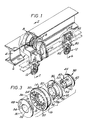
- FIGS 1 and 2 show perspective and front cross sectional views, respectively, of a trolley assembly in accordance with the instant invention.
- the trolley assembly is adapted toworkwith X-348, X-347 and similar overhead conveyors as are available from Green- line Corporation (Charlotte, North Carolina) and other suppliers.
- X-348 overhead conveyor I-beam 2 including web portion 4 and flange portion 6.
- the trolley assembly includes basically three components; wheel assembly 8, trolley bracket 10, and pendant 12. Due to symmetry of the trolley assembly, it will be appreciated that two identical wheel assemblies and two identical trolley brackets (left and right) are used to make a complete trolley assembly. Only a single pendant is required for a complete trolley assembly. It will also be appreciated that the trolley assembly is adapted to have its wheel assemblies 8 run on flange portion 6 of I-beam 2. Sufficient space is provided between the right and left wheel assemblies 8 to prevent contact with the web portion 4 of I-beam 2. Similarly, sufficient space is provided between the right and left trolley brackets 10 to prevent contact with flange portion 6 of the I-beam 2.
- FIG 3 is shown an exploded view of a wheel assembly of the present invention.
- the wheel 14 is made of a thermoplastic material, e.g. polyacetal, and is preferably 57mm in diameter with a face-to-face thickness of about 18mm.
- a preferred thermoplastic material is ULTRAFORM-2320 from BASF.
- Wheel 14 has an annular surface 16 with a taper of approximately 20° with respect to the centre line of the wheel. It will be appreciated that the annular surface 16 could also have a round or flat shape as may be desired for a particular application.
- On the inside of wheel 14 is web portion 18 with ribs 20 which extend radially inward toward through hole 24. The web and the ribs are preferably 2.5mm in thickness.
- ribs 20 may be provided on both sides of flange 18. It will be further appreciated that the ribs do not extend all the way to the side wall of the wheel. Rather, they may be recessed approximately 2.5mm thereby providing a recess in the side wall of the wheel.
- the wheel is designed such that more than 70% of the wheel is made of flange and ribs having a wall thickness of only 2.5mm and only at the annular outer surface (the portion which rotates against the I-beam) does the wall thickness increase to about 7mm.
- the wall thickness of prior art wheels is about 15-17mm.
- Bushing 28 includes face portion 30 and collar 32 and provides a through hole 34.
- the bushing 28 is made of an internally lubricated thermoplastic, e.g. polyacetal.
- a preferred thermoplastic material is DeirinAF313 from DuPontwhich has a lubricant in the material.
- the face portion preferably has a thickness of2.5mm and the collar portion preferably has a thickness of 4mm.
- On the back of the face portion is provided at least one rib 36 having a thickness of 2.5mm.
- FIG 3 further shows an axle of the wheel assembly 8.
- the axle 38 is preferably made of reinforced nylon.
- a preferred reinforced nylon material is RTP-205 from Fiberit Corp.
- Axle 38 includes side bearing surface 40, bevelled head 42, and shoulder 44.
- the axle provides through hole 46 with recess 48 adapted to contain a bolt head therein. (See Figure 2).
- the recess may be adapted to capture the bolt head and prevent its rotation by making recess 48, for example, six sided.
- the recess may be adapted to capture the nut of a bolt. It will be appreciated that the recess 48 may be designed to capture any configuration of bolt head or nut.
- axle 38 On the opposite side of axle 38 from recess 48 is mating face 50 which includes at least one pin 52 having a preferred diameter of 3mm.
- pin 52 On the opposite side of axle 38 from recess 48 is mating face 50 which includes at least one pin 52 having a preferred diameter of 3mm.
- cylindrical bearing surface 40 and shoulder 44 of axle 38 are adapted to rotatably contact the inside of collar 32 and the front of face portion 30 of bushing 28.
- shoulder 44 prevents axial movement of the wheel 14 and bevelled head 42 of axle 38 provides a smoother profile to the wheel assembly when in use.
- Figure 2 shows a cross sectional view of a complete wheel assembly.
- a bushing 28 is inserted on eitherside of the wheel 14 and due to symmetry of the inside configuration of the wheel, two identical bushings may be used for each wheel.
- ribs 36 of bushing 28 interlocks with ribs 20 of wheel 14 preventing rotation of the bushing with respect to the wheel.
- face portion 30 of bushing 28 recesses into the recess in the side wall of wheel 14 to present a substantially smooth surface to the bushing/wheel interface.
- the outside surface (the circumference of the wheel) must be smooth in order to roll well against the I-beam.
- the outside surface should also preferably be from a material with a low wear factor and the proper friction to prevent the wheel from slipping against the I-beam rather than rolling.
- the inside surface must be very smooth, but with a minimum possible coefficient of friction and abrasion, in order to permit excellent rotation against the axle.
- the bushing is produced from a special plastic material having an inherent lubricant, such as Delrin AF313 from DuPont.
- the bushings interconnected with the wheel.
- the bushing has integral ribs which are located between the ribs of the wheel. The wheel with the two bushings (one on each side) may then act as one part which is made of two different materials.
- An additional advantage of the invention is that the bushing also prevents friction and abrasion between the wheel and the trolley bracket and between the wheel and the axle - both in the axial direction. Axial forces are created because of the horizontal distance between the load and the wheels and because of the sloped flange portion of the I-beam.
- the wheel assembly according to the invention creates a chamber between the bushing 28 and the wheel 14.
- This chamber not only saves material and improves the properties of the parts, but also can be used as a vessel for grease or other lubricants for trolley applications other than in processing plants.
- the bushing 28 may be designed to be sealed around the wheel 14, and a clearance provided between the two bushings to allow lubricant to exit from the chamber through the clearance between bushings 28 and the axle 38.
- a special greasing thread as are known in the art may also be provided.
- Figures 1 and 2 show perspective and cross sectional views respectively of a trolley bracket which is preferably made of reinforced nylon.
- a preferred reinforced nylon material is Nylon 6/6 ADEL AR16 from Adel Plastics.
- At the upper end of trolley bracket 10 is provided through hole 56 and axle face 58 which is designed to allow free rotation against face portion 30 of bushing 28 of the wheel assembly 8.
- axle face 58 is provided at least one pin recess 60 which is adapted to accept pin 52 from axle 38 in the trolley asembly creating an interlock to prevent rotation of the axle should the connecting bolt loosen.
- the upper portion of trolley bracket 10 is generally U-shaped in cross section and includes an essentially flat portion preferably 5mm in thickness with stiffening ribs on either side, again preferably 5mm in thickness.
- trolley bracket 10 On the lower portion of trolley bracket 10 is provided pendant face 70 which is adapted to mate with a pendant. The face-to-face distance between axle face 58 and pendant face 70 is preferaby about 26mm. On the lower portion of trolley bracket 10 are provided bolt holes 66 for attaching the trolley bracket to another similar trolley bracket and a pendant to form a trolley assembly.
- the trolley bracket has been designed to have a moment of intertia such that the bending stresses are maintained low enough to permit carrying a continuous load of at least 100kg per bracket.
- the surface of the trolley bracket is preferably very smooth with high radii in order to prevent any accumulation of dirt.
- Figures 5 and 2 show perspective and cross sectional views, respectively, of a pendant 12 for use with the trolley assembly.
- the pendant has a preferred thickness of 5mm.
- Pendant 12 is preferably made of reinforced nylon.
- a preferred reinforced nylon material isADELAR-16 from Adel Plastics.
- Pendant 12 provides through holes 74 for connection with trolley brackets 10.
- Pendant 12 is adapted to be mated between two pendant faces of opposing trolley brackets.
- Pendant 12 presents a rounded lower end 78 to the trolley assembly.
- the weight of the pendant made according to the invention is about 29gr.
- FIGS 1 and 6 show perspective and cross sectional views, respectively, of an H-attachment assembly, including two H-attachments and a pendant, as may be used with the trolley assembly.
- the H-attachment is preferably made of a reinforced nylon.
- a preferred reinforced nylon isADELAR-16fromAdel Plastics.
- the H-attachment 80 has a substantially planar surface preferably 4mm in thickness with stiffening ribs 82 and including bolt holes 86 to attach one such H-attachment on each side of a pendant 12. Stiffening ribs 82 also define a channel portion 88 for the conveyor chain similar to the channel portion in the trolley assembly.
- the weight of the H-attachment made according to the invention is only 18gr while a prior art metal H-attachment weighs about 80gr.
- the components which make up the trolley assembly i.e. the wheel assembly, the trolley bracket, the pendant and the H-attachment assembly can be replaced on a one-to-one basis with parts of prior art trolley assemblies.
- axle and trolley bracket are described herein as being two separate components, the trolley bracket may be integrally formed with the axle as shown in Figure 7. This arrangement may be preferable for certain applications and results in fewer individual components for the trolley assembly.
Landscapes
- Engineering & Computer Science (AREA)
- Mechanical Engineering (AREA)
- General Engineering & Computer Science (AREA)
- Carriers, Traveling Bodies, And Overhead Traveling Cranes (AREA)
- Vehicle Body Suspensions (AREA)
- Body Structure For Vehicles (AREA)
- Handcart (AREA)
Applications Claiming Priority (2)
| Application Number | Priority Date | Filing Date | Title |
|---|---|---|---|
| US87139392A | 1992-04-21 | 1992-04-21 | |
| US871393 | 1992-04-21 |
Publications (1)
| Publication Number | Publication Date |
|---|---|
| EP0567295A1 true EP0567295A1 (fr) | 1993-10-27 |
Family
ID=25357352
Family Applications (1)
| Application Number | Title | Priority Date | Filing Date |
|---|---|---|---|
| EP93303050A Ceased EP0567295A1 (fr) | 1992-04-21 | 1993-04-20 | Assemblage de chariot roulant pour convoyeur |
Country Status (7)
| Country | Link |
|---|---|
| US (1) | US5357868A (fr) |
| EP (1) | EP0567295A1 (fr) |
| JP (1) | JPH06127883A (fr) |
| AU (1) | AU3702093A (fr) |
| BR (1) | BR9301618A (fr) |
| CA (1) | CA2094572A1 (fr) |
| MX (1) | MX9302223A (fr) |
Cited By (3)
| Publication number | Priority date | Publication date | Assignee | Title |
|---|---|---|---|---|
| EP1052198A1 (fr) * | 1999-05-03 | 2000-11-15 | Cersa NV (Société Anonyme) | Convoyeur utilisé dans l'industrie pour acheminer des pièces en nombre important |
| WO2007039338A1 (fr) * | 2005-10-01 | 2007-04-12 | Demag Cranes & Components Gmbh | Dispositif pour suspendre un rail, notamment un rail de roulement d'un convoyeur suspendu ou d'un engin de levage |
| WO2012048864A1 (fr) * | 2010-10-12 | 2012-04-19 | Wolffkran Holding Ag | Chariot roulant en matière plastique renforcée par des fibres de carbone |
Families Citing this family (21)
| Publication number | Priority date | Publication date | Assignee | Title |
|---|---|---|---|---|
| JPH08230665A (ja) * | 1995-02-22 | 1996-09-10 | Central Motor Co Ltd | トロリー |
| US6733728B1 (en) * | 1996-03-11 | 2004-05-11 | Hitachi, Ltd. | Analyzer system having sample rack transfer line |
| US5971618A (en) | 1996-05-26 | 1999-10-26 | Valu Engineering, Inc. | Flange bearing having reinforced molded housing |
| US5681117A (en) * | 1996-08-09 | 1997-10-28 | Deere & Company | Retainer for reel toothbar bearing |
| US6205929B1 (en) | 1998-01-15 | 2001-03-27 | Vgk Inc. | Trolley wheel |
| US5916066A (en) * | 1998-02-27 | 1999-06-29 | Chen; Ping | Wheel assembly adapted to be mounted on a wheel-bearing tube of an exerciser without the need for a locking bolt |
| JP2003130045A (ja) * | 2001-10-25 | 2003-05-08 | Pentax Corp | 軸受構造 |
| US20040041462A1 (en) * | 2002-08-29 | 2004-03-04 | Hicks E. David | Cart wheel with molded bearing components |
| US6915745B2 (en) * | 2003-01-17 | 2005-07-12 | Tac Lube, Llc | Self-lubricating overhead conveyor system |
| US20070261590A1 (en) * | 2006-05-11 | 2007-11-15 | Vgk, Inc. | Trolley wheel assembly |
| US7775162B1 (en) * | 2006-08-07 | 2010-08-17 | Cislo Lawrence | Roller for trolley assembly |
| ITBO20060638A1 (it) * | 2006-09-18 | 2008-03-19 | Emilsider Meccanica | Rotella auto-orientabile per mobili. |
| JP2009220723A (ja) * | 2008-03-17 | 2009-10-01 | Honda Motor Co Ltd | 小型艇の操舵装置 |
| US8702178B2 (en) * | 2009-12-23 | 2014-04-22 | Oconomowoc Mfg. Corp. | Trolley wheel technology |
| KR102312692B1 (ko) * | 2017-09-20 | 2021-10-18 | 현덕산기주식회사 | 분리형 트롤리 |
| KR102285406B1 (ko) * | 2017-09-20 | 2021-08-05 | 현덕산기주식회사 | 분리형 트롤리 |
| US12030341B2 (en) | 2017-11-27 | 2024-07-09 | Omco Sumo, Inc. | Caster braking system technology |
| US11498360B2 (en) | 2019-05-21 | 2022-11-15 | Ngs Capital Management, Llc | Hybrid bearing arrangement caster technology |
| WO2021081587A1 (fr) * | 2019-10-31 | 2021-05-06 | Bomac Engineering Pty. Ltd. | Perfectionnements se rapportant à des systèmes de rail et chariot |
| JP7178130B1 (ja) * | 2021-09-01 | 2022-11-25 | 小野谷機工株式会社 | 車両用作業装置 |
| CN117023202B (zh) * | 2023-09-09 | 2025-10-28 | 江苏中矿重型装备有限公司 | 一种自动化散状物料移动堆料机的行走回转定位装置 |
Citations (7)
| Publication number | Priority date | Publication date | Assignee | Title |
|---|---|---|---|---|
| US1721759A (en) * | 1928-10-17 | 1929-07-23 | Jervis B Webb | Chain conveyer |
| US4178856A (en) * | 1978-07-03 | 1979-12-18 | Dearborn Fabricating & Engineering Company | Wheel assembly for overhead conveyor |
| US4228738A (en) * | 1978-09-22 | 1980-10-21 | Forshee David J | Conveyor trolley construction |
| GB2097486A (en) * | 1981-04-20 | 1982-11-03 | Kamatics Corp | Bearings |
| EP0243718A1 (fr) * | 1986-04-26 | 1987-11-04 | INA Wälzlager Schaeffler KG | Elément de construction en matériau polymère injecté ou moulé |
| WO1992014665A1 (fr) * | 1991-02-26 | 1992-09-03 | Vfv Polymers Pty. Ltd. | Train de roulement de convoyeur |
| US5156533A (en) * | 1985-10-15 | 1992-10-20 | Hoffman Frank F | Replaceable plastic trolley wheel and method |
Family Cites Families (16)
| Publication number | Priority date | Publication date | Assignee | Title |
|---|---|---|---|---|
| US2759592A (en) * | 1953-02-24 | 1956-08-21 | Dearborn Fabricating & Enginee | Wheel mounting for conveyor |
| US3268062A (en) * | 1964-10-07 | 1966-08-23 | Gladstone Ben | Overhead conveyer trolley |
| DE2118232A1 (en) * | 1971-04-15 | 1972-11-02 | Industria Hans H. Tüxen KG, 2362 Wahlstedt | Chain conveyor - with plastic linkages,and unaffected by chemicals |
| GB1391914A (en) * | 1971-10-05 | 1975-04-23 | British Mathews Ltd | Conveyor chains |
| AT336491B (de) * | 1973-08-04 | 1977-05-10 | Interroll Foerdertechnik Gmbh | Zerlegbare gelenkkette |
| GB1394640A (en) * | 1973-10-24 | 1975-05-21 | Gill Co Ltd Stewart | Wheels or rollers for conveyors |
| US4109343A (en) * | 1976-05-10 | 1978-08-29 | C. L. Frost & Son, Inc. | Trolley wheel assembly |
| DE3030870A1 (de) * | 1979-08-29 | 1981-03-26 | Bando Chemical Industries Ltd., Kobe, Hyogo | Selbstschmierendes lager |
| US4441601A (en) * | 1981-04-20 | 1984-04-10 | C. L. Frost & Son, Inc. | Plastic conveyor roller and method of making same |
| US4484525A (en) * | 1981-07-06 | 1984-11-27 | Formall Syn-Trac Systems, Inc. | Plastic monorail conveyor trolley |
| US4433627A (en) * | 1981-07-29 | 1984-02-28 | Formall Syn-Trac Systems, Inc. | Plastic conveyor trolley with bearings |
| US4471867A (en) * | 1982-07-06 | 1984-09-18 | Formall Syn-Trac Systems, Inc. | Plastic monorail conveyor structure |
| US4467911A (en) * | 1982-07-14 | 1984-08-28 | Formall Syn-Trac Systems, Inc. | Plastic clevis for conveyor trolley and hanger |
| US4467913A (en) * | 1982-12-13 | 1984-08-28 | Formall Syn-Trac Systems, Inc. | Plastic monorail conveyor drive chain wheel |
| FR2629318B1 (fr) * | 1988-04-05 | 1990-12-14 | Delsey Soc | Roue en particulier pour bagages |
| DE4031685C3 (de) * | 1990-10-04 | 2001-11-08 | Mannesmann Ag | Laufradblock |
-
1993
- 1993-04-16 MX MX9302223A patent/MX9302223A/es unknown
- 1993-04-19 AU AU37020/93A patent/AU3702093A/en not_active Abandoned
- 1993-04-20 EP EP93303050A patent/EP0567295A1/fr not_active Ceased
- 1993-04-20 BR BR9301618A patent/BR9301618A/pt not_active Application Discontinuation
- 1993-04-21 JP JP5119005A patent/JPH06127883A/ja active Pending
- 1993-04-21 CA CA002094572A patent/CA2094572A1/fr not_active Abandoned
- 1993-12-30 US US08/176,498 patent/US5357868A/en not_active Expired - Fee Related
Patent Citations (7)
| Publication number | Priority date | Publication date | Assignee | Title |
|---|---|---|---|---|
| US1721759A (en) * | 1928-10-17 | 1929-07-23 | Jervis B Webb | Chain conveyer |
| US4178856A (en) * | 1978-07-03 | 1979-12-18 | Dearborn Fabricating & Engineering Company | Wheel assembly for overhead conveyor |
| US4228738A (en) * | 1978-09-22 | 1980-10-21 | Forshee David J | Conveyor trolley construction |
| GB2097486A (en) * | 1981-04-20 | 1982-11-03 | Kamatics Corp | Bearings |
| US5156533A (en) * | 1985-10-15 | 1992-10-20 | Hoffman Frank F | Replaceable plastic trolley wheel and method |
| EP0243718A1 (fr) * | 1986-04-26 | 1987-11-04 | INA Wälzlager Schaeffler KG | Elément de construction en matériau polymère injecté ou moulé |
| WO1992014665A1 (fr) * | 1991-02-26 | 1992-09-03 | Vfv Polymers Pty. Ltd. | Train de roulement de convoyeur |
Cited By (8)
| Publication number | Priority date | Publication date | Assignee | Title |
|---|---|---|---|---|
| EP1052198A1 (fr) * | 1999-05-03 | 2000-11-15 | Cersa NV (Société Anonyme) | Convoyeur utilisé dans l'industrie pour acheminer des pièces en nombre important |
| US6241082B1 (en) * | 1999-05-03 | 2001-06-05 | Cersa N.V. Societe Anonyme | Conveyor for use in the automotive industry |
| WO2007039338A1 (fr) * | 2005-10-01 | 2007-04-12 | Demag Cranes & Components Gmbh | Dispositif pour suspendre un rail, notamment un rail de roulement d'un convoyeur suspendu ou d'un engin de levage |
| US7503263B2 (en) | 2005-10-01 | 2009-03-17 | Demag Cranes & Components Gmbh | Device for suspending a rail of an overhead conveyor or a hoisting machine |
| RU2378182C2 (ru) * | 2005-10-01 | 2010-01-10 | ДЕМАГ КРЕЙНЗ ЭНД КОМПОНЕНТС ГмбХ | Устройство для крепления направляющей, в частности, рельса подвесного конвейера или подъемного механизма |
| US7784627B2 (en) | 2005-10-01 | 2010-08-31 | Demag Cranes & Components Gmbh | Device for suspending a rail, particularly a running rail of an overhead conveyor or of a lifting apparatus |
| CN101272981B (zh) * | 2005-10-01 | 2012-08-01 | 德马格起重机及部件有限公司 | 用于悬挂导轨的装置 |
| WO2012048864A1 (fr) * | 2010-10-12 | 2012-04-19 | Wolffkran Holding Ag | Chariot roulant en matière plastique renforcée par des fibres de carbone |
Also Published As
| Publication number | Publication date |
|---|---|
| MX9302223A (es) | 1994-07-29 |
| CA2094572A1 (fr) | 1993-10-22 |
| US5357868A (en) | 1994-10-25 |
| BR9301618A (pt) | 1993-10-26 |
| JPH06127883A (ja) | 1994-05-10 |
| AU3702093A (en) | 1993-10-28 |
Similar Documents
| Publication | Publication Date | Title |
|---|---|---|
| EP0567295A1 (fr) | Assemblage de chariot roulant pour convoyeur | |
| US4228738A (en) | Conveyor trolley construction | |
| US4433627A (en) | Plastic conveyor trolley with bearings | |
| US8967371B2 (en) | Stub shaft and bearing assembly and conveyor idler roller incorporating same | |
| US8702178B2 (en) | Trolley wheel technology | |
| CA2456986A1 (fr) | Ensemble interface resistant a l'usure, plus particulierement, roulement a rouleaux ou a chaines resistant a l'usure | |
| US3365253A (en) | Self-aligning antifriction-bearing equipped roller | |
| MXPA02009589A (es) | Montaje de cadena transportadora de pista cubierta. | |
| US5281033A (en) | Housed bearing assembly with sealed roller | |
| EP0739833A1 (fr) | Transporteurs | |
| US5566623A (en) | Wheel and bearing system for a load transporting overhead trolley assembly | |
| EP0513271A4 (en) | Sealed roller assembly | |
| US4858752A (en) | Wheel assembly for conveyer system | |
| EP1237803B1 (fr) | Composants de convoyeurs | |
| CA2119062C (fr) | Roulement a portees chanfreinees | |
| GB1578349A (en) | Bearing assemblies | |
| US3680933A (en) | Idler roll structure with improved bearing seal assembly | |
| CA1153410A (fr) | Roulement avec gorge interieure amelioree | |
| EP0572499B1 (fr) | Train de roulement de convoyeur | |
| US20240408966A1 (en) | Corrosion-resistant trolley wheel | |
| US20250276853A1 (en) | No lube conveyor chain | |
| CS198283B2 (cs) | Masivní klec dvouřadového naklápěciho ložiska, vedená vnějším kroužkem | |
| AU1327092A (en) | Conveyor trolley wheel assembly |
Legal Events
| Date | Code | Title | Description |
|---|---|---|---|
| PUAI | Public reference made under article 153(3) epc to a published international application that has entered the european phase |
Free format text: ORIGINAL CODE: 0009012 |
|
| AK | Designated contracting states |
Kind code of ref document: A1 Designated state(s): ES FR GB IT NL |
|
| 17P | Request for examination filed |
Effective date: 19940124 |
|
| 17Q | First examination report despatched |
Effective date: 19950725 |
|
| GRAG | Despatch of communication of intention to grant |
Free format text: ORIGINAL CODE: EPIDOS AGRA |
|
| STAA | Information on the status of an ep patent application or granted ep patent |
Free format text: STATUS: THE APPLICATION HAS BEEN REFUSED |
|
| 18R | Application refused |
Effective date: 19960910 |