EP0567813A2 - Vorrichtung zur Messung der Feuchtigkeit in Öfen, insbesondere Nahrungsmittelöfen - Google Patents
Vorrichtung zur Messung der Feuchtigkeit in Öfen, insbesondere Nahrungsmittelöfen Download PDFInfo
- Publication number
- EP0567813A2 EP0567813A2 EP93105657A EP93105657A EP0567813A2 EP 0567813 A2 EP0567813 A2 EP 0567813A2 EP 93105657 A EP93105657 A EP 93105657A EP 93105657 A EP93105657 A EP 93105657A EP 0567813 A2 EP0567813 A2 EP 0567813A2
- Authority
- EP
- European Patent Office
- Prior art keywords
- cooking
- humidity
- cavity
- measurement arrangement
- heat
- Prior art date
- Legal status (The legal status is an assumption and is not a legal conclusion. Google has not performed a legal analysis and makes no representation as to the accuracy of the status listed.)
- Granted
Links
Images
Classifications
-
- H—ELECTRICITY
- H05—ELECTRIC TECHNIQUES NOT OTHERWISE PROVIDED FOR
- H05B—ELECTRIC HEATING; ELECTRIC LIGHT SOURCES NOT OTHERWISE PROVIDED FOR; CIRCUIT ARRANGEMENTS FOR ELECTRIC LIGHT SOURCES, IN GENERAL
- H05B6/00—Heating by electric, magnetic or electromagnetic fields
- H05B6/64—Heating using microwaves
- H05B6/642—Cooling of the microwave components and related air circulation systems
-
- A—HUMAN NECESSITIES
- A21—BAKING; EDIBLE DOUGHS
- A21B—BAKERS' OVENS; MACHINES OR EQUIPMENT FOR BAKING
- A21B3/00—Parts or accessories of ovens
- A21B3/04—Air-treatment devices for ovens, e.g. regulating humidity
-
- A—HUMAN NECESSITIES
- A47—FURNITURE; DOMESTIC ARTICLES OR APPLIANCES; COFFEE MILLS; SPICE MILLS; SUCTION CLEANERS IN GENERAL
- A47J—KITCHEN EQUIPMENT; COFFEE MILLS; SPICE MILLS; APPARATUS FOR MAKING BEVERAGES
- A47J27/00—Cooking-vessels
- A47J27/14—Cooking-vessels for use in hotels, restaurants, or canteens
- A47J27/16—Cooking-vessels for use in hotels, restaurants, or canteens heated by steam
-
- F—MECHANICAL ENGINEERING; LIGHTING; HEATING; WEAPONS; BLASTING
- F24—HEATING; RANGES; VENTILATING
- F24C—DOMESTIC STOVES OR RANGES ; DETAILS OF DOMESTIC STOVES OR RANGES, OF GENERAL APPLICATION
- F24C15/00—Details
- F24C15/32—Arrangements of ducts for hot gases, e.g. in or around baking ovens
- F24C15/322—Arrangements of ducts for hot gases, e.g. in or around baking ovens with forced circulation
- F24C15/327—Arrangements of ducts for hot gases, e.g. in or around baking ovens with forced circulation with air moisturising
-
- F—MECHANICAL ENGINEERING; LIGHTING; HEATING; WEAPONS; BLASTING
- F24—HEATING; RANGES; VENTILATING
- F24C—DOMESTIC STOVES OR RANGES ; DETAILS OF DOMESTIC STOVES OR RANGES, OF GENERAL APPLICATION
- F24C7/00—Stoves or ranges heated by electric energy
- F24C7/08—Arrangement or mounting of control or safety devices
- F24C7/082—Arrangement or mounting of control or safety devices on ranges, e.g. control panels, illumination
- F24C7/085—Arrangement or mounting of control or safety devices on ranges, e.g. control panels, illumination on baking ovens
-
- G—PHYSICS
- G01—MEASURING; TESTING
- G01N—INVESTIGATING OR ANALYSING MATERIALS BY DETERMINING THEIR CHEMICAL OR PHYSICAL PROPERTIES
- G01N25/00—Investigating or analyzing materials by the use of thermal means
- G01N25/56—Investigating or analyzing materials by the use of thermal means by investigating moisture content
- G01N25/66—Investigating or analyzing materials by the use of thermal means by investigating moisture content by investigating dew-point
- G01N25/68—Investigating or analyzing materials by the use of thermal means by investigating moisture content by investigating dew-point by varying the temperature of a condensing surface
-
- H—ELECTRICITY
- H05—ELECTRIC TECHNIQUES NOT OTHERWISE PROVIDED FOR
- H05B—ELECTRIC HEATING; ELECTRIC LIGHT SOURCES NOT OTHERWISE PROVIDED FOR; CIRCUIT ARRANGEMENTS FOR ELECTRIC LIGHT SOURCES, IN GENERAL
- H05B6/00—Heating by electric, magnetic or electromagnetic fields
- H05B6/64—Heating using microwaves
- H05B6/6447—Method of operation or details of the microwave heating apparatus related to the use of detectors or sensors
- H05B6/645—Method of operation or details of the microwave heating apparatus related to the use of detectors or sensors using temperature sensors
-
- H—ELECTRICITY
- H05—ELECTRIC TECHNIQUES NOT OTHERWISE PROVIDED FOR
- H05B—ELECTRIC HEATING; ELECTRIC LIGHT SOURCES NOT OTHERWISE PROVIDED FOR; CIRCUIT ARRANGEMENTS FOR ELECTRIC LIGHT SOURCES, IN GENERAL
- H05B6/00—Heating by electric, magnetic or electromagnetic fields
- H05B6/64—Heating using microwaves
- H05B6/6447—Method of operation or details of the microwave heating apparatus related to the use of detectors or sensors
- H05B6/6458—Method of operation or details of the microwave heating apparatus related to the use of detectors or sensors using humidity or vapor sensors
-
- Y—GENERAL TAGGING OF NEW TECHNOLOGICAL DEVELOPMENTS; GENERAL TAGGING OF CROSS-SECTIONAL TECHNOLOGIES SPANNING OVER SEVERAL SECTIONS OF THE IPC; TECHNICAL SUBJECTS COVERED BY FORMER USPC CROSS-REFERENCE ART COLLECTIONS [XRACs] AND DIGESTS
- Y02—TECHNOLOGIES OR APPLICATIONS FOR MITIGATION OR ADAPTATION AGAINST CLIMATE CHANGE
- Y02P—CLIMATE CHANGE MITIGATION TECHNOLOGIES IN THE PRODUCTION OR PROCESSING OF GOODS
- Y02P60/00—Technologies relating to agriculture, livestock or agroalimentary industries
- Y02P60/80—Food processing, e.g. use of renewable energies or variable speed drives in handling, conveying or stacking
Definitions
- This invention relates to an arrangement for measuring the humidity in ovens in general, and in particular in food-cooking ovens, so as to regulate the degree of humidity to the pre-determined level during food cooking processes performed in appliances of this kind.
- Food-cooking ovens are known from the prior art to be constituted substantially by a box-like outer casing delimiting an inner cooking cavity in which the food to be cooked is arranged, a forced circulation of hot air being brought about in said cooking cavity through a gas-fuelled or electric heat generator and at least a fan.
- thermostatic control systems to regulate the food cooking temperature, which are associated with temperature selector means that are to be set on the desired temperature value before starting any cooking process to be performed, in accordance with the kind and the amount of food to be cooked.
- the thermostatic temperature control systems equipping said ovens operate to keep the food cooking temperature within pre-defined limits inside the cooking cavity, in general by energizing and de-energizing both the heat generator and/or the possibly provided steam generator, if the ovens are intended to also cook by steam, and the air-moving fan, so as to vary in an appropriate way the flow of air circulating through the cooking cavity.
- humidity measurement devices are known in connection with applications of a different kind. These are generally constituted by semiconductor sensing means which are arranged in the moist environment to be controlled, and are connected with electrical bridge-type measurement circuits that are adapted to detect the corresponding electric quantities generated by said sensing means and to automatically convert them into corresponding humidity levels prevailing in said moist environment.
- Further humidity measuring devices are constituted by elements measuring the concentration of oxygen in gas mixtures, such as for instance in the case of zirconium oxide cells, according to per sè known principles of operation.
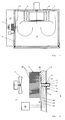
- FIG. 1 shows schematically a food cooking oven 6 featuring forced circulation of the hot air generated by appropriate gas-fuelled or electric heat generators of some per sè known type (not shown), or even some further steam alone and/or combined hot air/steam and/or microwave alone and/or combined microwave/hot-air/steam cooking mode facilities, said oven comprising substantially a metal box-like outer casing 7 delimiting an inner cooking cavity 8 in which the food items to be cooked are arranged, and which is equipped with a fan 8 for said forced circulation of the hot air, said cavity being in this particular case (in which the oven with forced hot-air circulation is specially considered) divided internally by a partition wall 9 into a further cavity 10 communicating with the afore considered cavity 8 and housing a fan 11 whose function will be described further on.
- the oven being considered here further comprises the humidity measurement arrangement 12 according to the present invention, which is housed in the cavities 8 and 10 and is built anda operating as described in detail hereinafter.
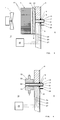
- FIG 2 shows schematically the humidity measurement arrangement 12 according to the present invention, in a first possible embodiment thereof.
- said humidity measurement arrangement consists substantially of at least a body 13 made of highly heat-conductive metal to various geometrical shapes and extending preferably in a rectilinear direction, which can be seen as being inserted through a corresponding through-passing hole 14 that is made in the partition wall 9 separating the cooking cavity 8 from the cavity 10 that houses the fan 11.
- Said heat-conductive metal body 13 is in an advantageous way constituted by an internally hollow copper body, while its outer surface 15 is separated by the sheet-metal material of the partition wall 9 by means of a small bushing 16 made of a per sè known heat-insulating material, or by means of some other separating element of similar material, which is inserted through the peripheral edge of said sheet-metal delimiting said through-passing hole 14.
- the heat-conductive metal body 13 is closed by a small metal bottom plate 17 at its end penetrating for a short length into the cooking cavity 8 of the oven, and is further closed by a similar small metal bottom plate 18 even at its opposite end extending into the other cavity 10 of the oven, the latter metal bottom plate being connected or integrally made with a highly heat-conductive metal element acting as a heat-sink, which in this particular case is constituted by a metal rectilinear plate 19 which is applied at right angle against the corresponding outer surface of the small bottom plate 18 and is provided with a plurality of separate fins 20 directed toward the fan 11 and arranged so as to be hit by the flow of air generated by the same fan, in view of causing in this way the entire surface of the plate 19, and hence the respective end of the metal body 13 defined by the small bottom plate 18, to gradually cool down.
- a highly heat-conductive metal element acting as a heat-sink which in this particular case is constituted by a metal rectilinear plate 19 which is applied at right angle against the corresponding
- At least two temperature sensors are applied inside said metal body 13 , preferably in the form of thermocouples 21 and 22, ie. a first thermocouple 21 applied against the inner surface of the end bottom plate 17 and a second thermocouple 22 applied against the inner surface of the opposite end bottom plate 18, respectively, said thermocouples being connected, through respective electrical lead wires 23 and 24 passing through the inner cavity of said metal body 13, with an appropriate oven control device that, in a most advantageous way, may be made in the form of an electronic microprocessor 25 housed in an appropriate, separate site of the oven to perform the functions that will be better described hereinafter.
- the humidity measurement arrangement is constituted by at least a further temperature sensor, preferably in the form of another thermocouple 26, which penetrates partially into the cooking cavity 8 of the oven through the afore cited partition wall 9, to the purpose of detecting the temperature of the hot air circulated through said cooking cavity, said temperature sensor being connected with its free end with said electronic microprocessor 25 through a respective electrical lead wire 27.
- the described arrangement of the temperature sensors 21, 22 and 26 enables not only the cooking temperature T1 of the food items in the cooking cavity 8 to be measured through said temperature sensor 26, but also the temperatures T2 and T3 of the end bottom plates 17 and 18 of said metal body 13 to be measured through the respective temperature sensors 21 and 22, wherein the temperature T2 of the end bottom plate 17, being in particular subject to direct contact with the hot air circulated in the cooking cavity 8, is higher than the temperature T3 of the end bottom plate 18 which on the contrary is cooled down by the heat-conductive contact with the metal heat-sink element 19.
- the temperature sensor 21 that is associated therewith will immediately detect said temperature T2 and convey the corresponding information to the electronic microprocessor 25, which will in turn determine the respective measurement value, along with the measurement values relating to both the temperature T3 of the end bottom plate 18 and the temperature T1 of the cooking cavity 8, which are detected by the temperature sensors 22 and 26, respectively.
- the humidity measurement arrangement is capable of automatically and instantaneously determining the humidity content of the air inside the oven, in correspondence of the afore cited dew point, by taking advantage of the physical principle according to which in a gas mixture containing also water vapour (such as in the case of the moist air contained in the cooking cavity of the oven), said water vapour will fully condense in correspondence of its dew point, which is a variable quantity depending on the ambient pressure, whereas the remaining gaseous mixture will on the contrary not be condensable, so that it will remain in its gaseous state. It should further be noticed that this condensation temperature, or dew point, is also dependent on the humidity content of the gaseous mixture.
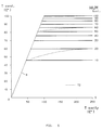
- FIG. 5 illustrates a chart which should be used in order to better understand the operation of the humidity measurement arrangement according to the present invention.
- This chart indicates how the condensation temperature, or dew point, (indicated in the ordinates) of the water vapour contained in a gaseous mixture, ie. in this particular case the moist air contained in the cooking cavity of the oven, changes according to the ambient heating-up temperature (indicated in the abscissae), ie. in this particular case the food heating-up temperature in the cooking cavity of the oven.
- This chart has been plotted with reference to a constant ambient pressure, ie. in this particular case the pressure of the ambient air, on the basis of the Mollier diagram for moist air, and extrapolating the corresponding values of the condensation temperature, or dew point, at said constant pressure.
- the water vapour heating-up temperatures in the cooking cavity of the oven turn out in general to be situated anywhere between ambient temperature and a highest possible value of approx. 250°C, based on said extrapolated values it is possible to determine, for said constant ambient pressure, the condensation temperature, or dew point, of said water vapour, ie. in this particular example for temperatures situated anywhere between the ambient temperature and 100°C, as a function of its humidity content.
- the humidity contents in vol.- percent of the water vapour which, as determined theoretically through the afore cited extrapolation, correspond to its respective condensation temperatures, are indicated with straight horizontal lines running parallelly to each other, each one of them duly marked with the respective humidity content.
- the straight inclined line B which starts from the point O where the cartesian axes meet, defines the delimitation zone between the air-water vapour mixture in its gaseous state (on the right side with respect to said straight line) and the condensed water vapour, ie. in its liquid state, (on the left side with respect to said straight line).
- the microprocessor automatically measures the humidity content of the air contained in the cooking cavity of the oven and, at the same time, is also capable of causing said humidity content to be regulated to pre-set values that will have been selected manually by means of appropriate selectors equipping the oven and associated with said microprocessor, by continuously comparing the actual humidity values with the pre-set ones that have been previously stored in a coded form in the memory of said microprocessor, so as to be capable of acting on the various functional component parts of the oven (ie. heat generator, steam generator, etc.) until the desired humidity content, corresponding to the one that has been pre-set through said selectors, is actually reached in the cooking cavity.
- the various functional component parts of the oven ie. heat generator, steam generator, etc.
- the humidity measurement arrangement according to the present invention may be used to both measure humidity under any cooking temperature condition, in a very reliable way and to a very accurate extent, and to carry out cooking processes under pre-set and variable humidity level conditions that will each time be appropriately selected by the user in accordance with the amount and the kind of the food items to be cooked, so as to bring about optimal cooking processes for the same food items, by keeping their flavour and properties nearly unaltered, and enable the operation performance and efficiency of the cooking ovens to be rationalized.
- FIG. 3 it can be noticed that it shows a second possible embodiment of the humidity measurement arrangement according to the present invention, wherein it can further be noticed that while the metal body 13 is unchanged with respect to the afore described embodiment, the heat-sink provision used in this case is provided in the form of a battery of per sè known Peltier elements, indicated with the reference numeral 28, which is also provided with separate fins 20 arranged so as to face the fan 11 and to be cooled by the flow of air generated by the same fan.
- the heat-sink provision used in this case is provided in the form of a battery of per sè known Peltier elements, indicated with the reference numeral 28, which is also provided with separate fins 20 arranged so as to face the fan 11 and to be cooled by the flow of air generated by the same fan.
- Figure 4 shows a further possible embodiment of the humidity measurement arrangement according to the present invention, wherein it can be noticed that around the terminal portion of the metal body 13 and the corresponding end 18, which are inserted in said separate cavity 10 of the oven, an innerly hollow cool-down metal element 32 is applied in tight contact therewith, the hollow section 33 thereof being such as to enable an appropriate cooling medium from a separate supply source (not shown) to be circulated therein.
- this humidity measurement arrangement may be used not only in cooking ovens, but also in ovens or heating equipment of a different type or kind, to different purposes or applications, such as for instance in laboratory equipment operating under controlled humidity conditions, without departing from the scopes of the present invention.
Landscapes
- Physics & Mathematics (AREA)
- Engineering & Computer Science (AREA)
- Electromagnetism (AREA)
- Chemical & Material Sciences (AREA)
- Life Sciences & Earth Sciences (AREA)
- Food Science & Technology (AREA)
- Health & Medical Sciences (AREA)
- General Engineering & Computer Science (AREA)
- Mechanical Engineering (AREA)
- Combustion & Propulsion (AREA)
- Analytical Chemistry (AREA)
- Biochemistry (AREA)
- General Health & Medical Sciences (AREA)
- General Physics & Mathematics (AREA)
- Immunology (AREA)
- Pathology (AREA)
- Investigating Or Analyzing Materials Using Thermal Means (AREA)
- Control Of High-Frequency Heating Circuits (AREA)
- Electric Ovens (AREA)
Applications Claiming Priority (2)
| Application Number | Priority Date | Filing Date | Title |
|---|---|---|---|
| ITPN920036A IT1258073B (it) | 1992-04-29 | 1992-04-29 | Dispositivo di misura dell'umidita' per forni, in particolare forni dicottura di alimenti |
| ITPN920036 | 1992-04-29 |
Publications (3)
| Publication Number | Publication Date |
|---|---|
| EP0567813A2 true EP0567813A2 (de) | 1993-11-03 |
| EP0567813A3 EP0567813A3 (de) | 1994-10-19 |
| EP0567813B1 EP0567813B1 (de) | 1997-09-03 |
Family
ID=11394674
Family Applications (1)
| Application Number | Title | Priority Date | Filing Date |
|---|---|---|---|
| EP93105657A Expired - Lifetime EP0567813B1 (de) | 1992-04-29 | 1993-04-06 | Vorrichtung zur Messung der Feuchtigkeit, insbesondere in Nahrungsmittelöfen |
Country Status (5)
| Country | Link |
|---|---|
| US (1) | US5272963A (de) |
| EP (1) | EP0567813B1 (de) |
| DE (1) | DE69313507T2 (de) |
| ES (1) | ES2109386T3 (de) |
| IT (1) | IT1258073B (de) |
Cited By (12)
| Publication number | Priority date | Publication date | Assignee | Title |
|---|---|---|---|---|
| EP0656174A1 (de) * | 1993-12-04 | 1995-06-07 | AEG Hausgeräte GmbH | Back- und Bratofen mit einem Garraum und einem Dampferzeuger für den Garraum |
| EP0701388B1 (de) * | 1994-09-09 | 2000-09-20 | ELECTROLUX ZANUSSI GRANDI IMPIANTI S.p.A. | Kochofen ausgestattet mit einem verbesserten Feuchtigkeitssensor |
| EP1371291A1 (de) | 2002-05-21 | 2003-12-17 | Olis S.p.A. | Feuchtigkeitsmess- und Abgleichvorrichtung, insbesondere in einen Nahrungsmittelofen |
| WO2004077952A1 (de) | 2003-03-05 | 2004-09-16 | Rational Ag | Verfahren zum steuern eines garprozesses |
| DE10309485A1 (de) * | 2003-03-05 | 2004-10-28 | Rational Ag | Verfahren zum Steuern eines Garprozesses |
| WO2007042168A1 (de) | 2005-10-10 | 2007-04-19 | Vereta Gmbh | Vorrichtung zur messung der kondensationstemperatur eines gases |
| EP1837600A3 (de) * | 2006-03-24 | 2009-01-28 | E.G.O. ELEKTRO-GERÄTEBAU GmbH | Verfahren zur Überwachung bzw. Steuerung oder Regelung eines geschlossenen Elektrowärmegerätes |
| CN105911094A (zh) * | 2016-06-23 | 2016-08-31 | 哈尔滨工业大学 | 微/纳米孔隙材料高温传热的测量装置及高温传热实验方法 |
| IT201600079080A1 (it) * | 2016-07-27 | 2018-01-27 | Primax S R L | Dispositivo di rilevamento della temperatura del punto di rugiada dell’atmosfera di una camera di trattamento termico |
| WO2018033385A1 (de) * | 2016-08-19 | 2018-02-22 | BSH Hausgeräte GmbH | Entfeuchten eines garraums |
| EP2639514B1 (de) * | 2012-03-14 | 2021-05-12 | BSH Hausgeräte GmbH | Gargerätevorrichtung |
| WO2021162644A1 (en) | 2020-02-12 | 2021-08-19 | Gorenje,D.O.O. | Environmental control system suitable to operate at high temperatures for transient conditions with controled condensation effect |
Families Citing this family (38)
| Publication number | Priority date | Publication date | Assignee | Title |
|---|---|---|---|---|
| SG46236A1 (en) * | 1992-06-03 | 1998-02-20 | Esec Sa | Apparatus for the heat treatment of a magazine for lead frames with electronic chips |
| US5451744A (en) * | 1992-11-10 | 1995-09-19 | Henny Penny Corporation | Rotisserie oven |
| US5660103A (en) * | 1993-05-05 | 1997-08-26 | Henny Penny Corporation | Humidity generating system |
| IT1268279B1 (it) * | 1994-07-29 | 1997-02-27 | Polin & C Spa Ing | Forno di cottura, in particolare per pane o prodotti di pasticceria |
| US5532456A (en) * | 1995-03-02 | 1996-07-02 | The Delfield Company | Temperature and humidity controllable doorless oven |
| US5680810A (en) * | 1996-08-09 | 1997-10-28 | Sham; John C. K. | Steam toaster oven |
| AU738500B2 (en) * | 1997-02-21 | 2001-09-20 | Taco Bell Corp. | Restaurant food preparation line |
| EP0926449B2 (de) * | 1997-12-23 | 2003-05-21 | eloma GmbH Grossküchentechnik | Verfahren zum Entfeuchten eines Garraumes eines Dampfgargerätes sowie Vorrichtung hierfür |
| DE19824172A1 (de) * | 1998-05-29 | 1999-12-09 | Rational Gmbh | Gargerät mit Energiespeicher- und Energieentnahmesystem |
| AU1855600A (en) * | 1998-10-22 | 2000-05-08 | Rational Ag | Cooking device with a catalyst |
| US6101925A (en) * | 1999-10-12 | 2000-08-15 | Lundar Electric Industrial Co., Ltd. | Humidity device for oven |
| US6344630B1 (en) * | 2000-10-25 | 2002-02-05 | Cambro Manufacturing Company | Thermoelectric heated food service cart |
| DE10060155A1 (de) * | 2000-12-04 | 2002-06-20 | Bsh Bosch Siemens Hausgeraete | Gargerät |
| DE10132581A1 (de) * | 2001-07-10 | 2003-01-30 | Imp Werke Ohg | Dampfgargerät |
| FI20011786A7 (fi) | 2001-09-10 | 2003-03-11 | Dieta Oy | Leivinuunin kosteuden mittausmenetelmä ja laite |
| US7308852B2 (en) * | 2001-12-28 | 2007-12-18 | Sharp Kabushiki Kaisha | Heating cooking device |
| US6952930B1 (en) | 2003-03-31 | 2005-10-11 | General Electric Company | Methods and apparatus for controlling refrigerators |
| US7220946B2 (en) | 2004-01-23 | 2007-05-22 | Hatco Corporation | Food container |
| ES2287836T3 (es) * | 2005-04-29 | 2007-12-16 | MKN MASCHINENFABRIK KURT NEUBAUER GMBH & CO. | Aparato de cocinado con una salida del recinto de cocinado y un sifon. |
| ITMO20050159A1 (it) * | 2005-06-22 | 2006-12-23 | Angelo Grandi Cucine Societa P | Sistema per il controllo dell'umidita'. |
| DE102005055773B4 (de) * | 2005-11-21 | 2008-04-10 | Miele & Cie. Kg | Dampfgargerät zur Wärmebehandlung von Speisen |
| DE102006058617B3 (de) * | 2006-12-11 | 2008-02-21 | Miele & Cie. Kg | Verfahren zur Bestimmung des zeitlichen Verlaufs der während eines Garvorgangs in einem Garraum eines Backofens von einem Gargut abgegebenen Dampfmenge sowie Vorrichtung zur Durchführung des Verfahrens |
| US8134101B2 (en) * | 2007-10-11 | 2012-03-13 | Hatco Corporation | Food container |
| US20110005409A1 (en) * | 2009-07-10 | 2011-01-13 | Hatco Corporation | Heated air curtain container with multiple temperature zones |
| WO2011110197A1 (de) | 2010-03-11 | 2011-09-15 | Bartec Gmbh | Vorrichtung und verfahren zum bestimmen des taupunktes eines gases |
| DE102010061472A1 (de) * | 2010-12-22 | 2012-06-28 | Miele & Cie. Kg | Gargerät |
| WO2013157185A1 (ja) * | 2012-04-16 | 2013-10-24 | エスペック株式会社 | 湿度計及びこの湿度計を備えた恒温恒湿槽 |
| US9841261B2 (en) * | 2013-04-29 | 2017-12-12 | Alto-Shaam, Inc. | Combination oven with peak power control |
| US11104502B2 (en) * | 2016-03-01 | 2021-08-31 | Jeffrey S. Melcher | Multi-function compact appliance and methods for a food or item in a container with a container storage technology |
| DE102016215650A1 (de) * | 2016-08-19 | 2018-02-22 | BSH Hausgeräte GmbH | Haushaltsgargerät |
| EP3412973B1 (de) * | 2017-06-07 | 2024-02-28 | Electrolux Appliances Aktiebolag | Ofen mit einer anordnung zur erfassung von betriebsparametern innerhalb des ofenraumes |
| DE102017123322A1 (de) * | 2017-10-09 | 2019-04-11 | Rational Aktiengesellschaft | Verfahren zum Betreiben eines Gargeräts und Gargerät |
| US10747968B2 (en) | 2017-11-22 | 2020-08-18 | Jeffrey S. Melcher | Wireless device and selective user control and management of a wireless device and data |
| CN111195082B (zh) * | 2018-11-19 | 2022-02-18 | 宁波方太厨具有限公司 | 一种食物焦糊状态智能识别方法 |
| CN111870140A (zh) * | 2020-07-30 | 2020-11-03 | 佛山市顺德区美的电热电器制造有限公司 | 烹饪设备的控制方法、烹饪设备和计算机可读存储介质 |
| EP3770508B1 (de) * | 2020-11-27 | 2024-11-27 | V-Zug AG | Garverfahren zum betreiben eines gargerätes sowie gargerät |
| EP4112465B1 (de) * | 2021-06-28 | 2025-02-19 | B/E Aerospace, Inc. | Kücheneinsatz mit ofen für die luftfahrt |
| EP4579134A1 (de) * | 2023-12-26 | 2025-07-02 | Arçelik Anonim Sirketi | Feuchtigkeitsmessvorrichtung und dampfofen damit |
Family Cites Families (18)
| Publication number | Priority date | Publication date | Assignee | Title |
|---|---|---|---|---|
| FR1343830A (fr) * | 1962-10-30 | 1963-11-22 | Zentralinstitut Fuer Automatis | Procédé et appareil de mesure de la teneur en eau d'un produit |
| US3712140A (en) * | 1971-03-29 | 1973-01-23 | United Aircraft Corp | Wet bulb temperature sensor |
| SU486263A1 (ru) * | 1972-12-02 | 1975-09-30 | Способ определени влажности воздуха | |
| US4462383A (en) * | 1982-06-09 | 1984-07-31 | Lincoln Manufacturing Company, Inc. | Impingement food preparation apparatus |
| JPS58194747U (ja) * | 1982-06-18 | 1983-12-24 | 大畠 隆 | 加工食品保管庫 |
| US4876426A (en) * | 1982-08-13 | 1989-10-24 | Smith Donald P | Method and apparatus for water vapor control in convection ovens |
| US4455924A (en) * | 1982-09-30 | 1984-06-26 | Alco Standard Corporation | Oven for cooking and flavoring meat products |
| FR2564308B1 (fr) * | 1984-05-17 | 1987-08-21 | Jovanovic Dragomir | Appareil de cuisson a injection de vapeur a pression atmospherique |
| CA1277548C (en) * | 1985-10-12 | 1990-12-11 | Ojima, Tadasu | Method of and an apparatus for making bread at home |
| US4700685A (en) * | 1986-05-09 | 1987-10-20 | Lincoln Foodservice Products, Inc. | Combination convection and steamer oven |
| AU575743B2 (en) * | 1986-05-15 | 1988-08-04 | Kabushiki Kaisha Toshiba | Circulating air cooker |
| DE3722282A1 (de) * | 1986-11-24 | 1988-06-01 | Convotherm Elektrogeraete | Vorrichtung zur waermebehandlung von nahrungsmitteln |
| FR2609532B1 (fr) * | 1987-01-08 | 1990-12-14 | Bourgeois Sc | Four a vapeur au gaz |
| SU1453291A1 (ru) * | 1987-03-19 | 1989-01-23 | Ровенское Производственное Объединение "Азот" Им.50-Летия Ссср | Устройство дл измерени точки росы |
| GB2207514A (en) * | 1987-06-12 | 1989-02-01 | Flour Milling & Baking Res | Apparatus for measuring atmospheric humidity in ovens |
| FR2629569B1 (fr) * | 1988-03-29 | 1990-08-17 | Armines | Procede et appareil de cuisson ou de rechauffage d'un aliment au moyen de vapeur d'eau |
| BE1001974A5 (fr) * | 1988-05-17 | 1990-05-02 | Itt Ind Belgium | Appareil de cuisson d'aliments. |
| US5014679A (en) * | 1989-09-18 | 1991-05-14 | Tecogen, Inc. | Gas fired combination convection-steam oven |
-
1992
- 1992-04-29 IT ITPN920036A patent/IT1258073B/it active IP Right Grant
-
1993
- 1993-04-06 EP EP93105657A patent/EP0567813B1/de not_active Expired - Lifetime
- 1993-04-06 DE DE69313507T patent/DE69313507T2/de not_active Expired - Fee Related
- 1993-04-06 ES ES93105657T patent/ES2109386T3/es not_active Expired - Lifetime
- 1993-04-26 US US08/052,505 patent/US5272963A/en not_active Expired - Fee Related
Cited By (17)
| Publication number | Priority date | Publication date | Assignee | Title |
|---|---|---|---|---|
| EP0656174A1 (de) * | 1993-12-04 | 1995-06-07 | AEG Hausgeräte GmbH | Back- und Bratofen mit einem Garraum und einem Dampferzeuger für den Garraum |
| EP0701388B1 (de) * | 1994-09-09 | 2000-09-20 | ELECTROLUX ZANUSSI GRANDI IMPIANTI S.p.A. | Kochofen ausgestattet mit einem verbesserten Feuchtigkeitssensor |
| EP1371291A1 (de) | 2002-05-21 | 2003-12-17 | Olis S.p.A. | Feuchtigkeitsmess- und Abgleichvorrichtung, insbesondere in einen Nahrungsmittelofen |
| WO2004077952A1 (de) | 2003-03-05 | 2004-09-16 | Rational Ag | Verfahren zum steuern eines garprozesses |
| DE10309486A1 (de) * | 2003-03-05 | 2004-09-23 | Rational Ag | Verfahren zum Steuern eines Garprozesses |
| DE10309485A1 (de) * | 2003-03-05 | 2004-10-28 | Rational Ag | Verfahren zum Steuern eines Garprozesses |
| DE10309486B4 (de) * | 2003-03-05 | 2006-05-24 | Rational Ag | Verfahren zum Regeln eines Garprozesses |
| US7196292B2 (en) | 2003-03-05 | 2007-03-27 | Rational Ag | Method for controlling a cooking process |
| WO2007042168A1 (de) | 2005-10-10 | 2007-04-19 | Vereta Gmbh | Vorrichtung zur messung der kondensationstemperatur eines gases |
| EP1837600A3 (de) * | 2006-03-24 | 2009-01-28 | E.G.O. ELEKTRO-GERÄTEBAU GmbH | Verfahren zur Überwachung bzw. Steuerung oder Regelung eines geschlossenen Elektrowärmegerätes |
| EP2639514B1 (de) * | 2012-03-14 | 2021-05-12 | BSH Hausgeräte GmbH | Gargerätevorrichtung |
| CN105911094A (zh) * | 2016-06-23 | 2016-08-31 | 哈尔滨工业大学 | 微/纳米孔隙材料高温传热的测量装置及高温传热实验方法 |
| CN105911094B (zh) * | 2016-06-23 | 2018-11-02 | 哈尔滨工业大学 | 微/纳米孔隙材料高温传热的测量装置及高温传热实验方法 |
| IT201600079080A1 (it) * | 2016-07-27 | 2018-01-27 | Primax S R L | Dispositivo di rilevamento della temperatura del punto di rugiada dell’atmosfera di una camera di trattamento termico |
| WO2018033385A1 (de) * | 2016-08-19 | 2018-02-22 | BSH Hausgeräte GmbH | Entfeuchten eines garraums |
| US11013074B2 (en) * | 2016-08-19 | 2021-05-18 | BSH Hausgeräte GmbH | Dehumidifying a cooking chamber |
| WO2021162644A1 (en) | 2020-02-12 | 2021-08-19 | Gorenje,D.O.O. | Environmental control system suitable to operate at high temperatures for transient conditions with controled condensation effect |
Also Published As
| Publication number | Publication date |
|---|---|
| EP0567813B1 (de) | 1997-09-03 |
| EP0567813A3 (de) | 1994-10-19 |
| DE69313507D1 (de) | 1997-10-09 |
| ITPN920036A0 (it) | 1992-04-29 |
| US5272963A (en) | 1993-12-28 |
| IT1258073B (it) | 1996-02-20 |
| ES2109386T3 (es) | 1998-01-16 |
| ITPN920036A1 (it) | 1993-10-29 |
| DE69313507T2 (de) | 1998-01-08 |
Similar Documents
| Publication | Publication Date | Title |
|---|---|---|
| EP0567813B1 (de) | Vorrichtung zur Messung der Feuchtigkeit, insbesondere in Nahrungsmittelöfen | |
| US20250155297A1 (en) | Wet bulb temperature sensor system and method for direct measurement of wet bulb temperature in an oven | |
| US8302527B2 (en) | Method for determining the variation with time of the amount of steam released from a food product during a cooking process in a cooking chamber of a baking oven | |
| US4286391A (en) | Control system for an automatic clothes dryer | |
| US10278532B2 (en) | Household appliance and electrical heating element for use in a household appliance | |
| CN105982520A (zh) | 烹饪用具 | |
| EP0701388A2 (de) | Verbesserte Feuchtigkeitssensor und mit diesem ausgestattetem Kochofen | |
| US20200326075A1 (en) | Automatic oven with humidity sensor | |
| US5402709A (en) | Method and apparatus for detecting steam in a volume of air and a steam generator and a steam cooking oven using such method and such apparatus | |
| KR19990028892A (ko) | 복수의 식품재료를 균일하게 가열하기 위한 방법 및 가열조리장치 | |
| WO2010008279A1 (en) | Heating element and method for operating such a heating element | |
| NO177243B (no) | Temperatursonde samt ovn forsynt med slik sonde | |
| EP0001396B1 (de) | Verfahren um Fleisch in einem Mikrowellenofen zu kochen | |
| US11617237B2 (en) | Cooking appliance | |
| US20210172610A1 (en) | Oven appliance having a humidity sensor | |
| US20230111723A1 (en) | Heat probe | |
| JPH0587345A (ja) | 閉成される調理室を有する料理装置 | |
| CN209231251U (zh) | 一种均热板性能快速评估装置 | |
| US2128462A (en) | Thermocouple hygrometer | |
| JP6909211B2 (ja) | 加熱調理器 | |
| CN223335941U (zh) | 烹饪装置 | |
| US12478208B2 (en) | Cooking adjustment system | |
| KR100691895B1 (ko) | 전기오븐의 온도센서 고정구조 | |
| EP1371291A1 (de) | Feuchtigkeitsmess- und Abgleichvorrichtung, insbesondere in einen Nahrungsmittelofen | |
| KR960010019Y1 (ko) | 식품증기 가열장치 |
Legal Events
| Date | Code | Title | Description |
|---|---|---|---|
| PUAI | Public reference made under article 153(3) epc to a published international application that has entered the european phase |
Free format text: ORIGINAL CODE: 0009012 |
|
| AK | Designated contracting states |
Kind code of ref document: A2 Designated state(s): CH DE ES FR GB IT LI NL SE |
|
| PUAL | Search report despatched |
Free format text: ORIGINAL CODE: 0009013 |
|
| AK | Designated contracting states |
Kind code of ref document: A3 Designated state(s): CH DE ES FR GB IT LI NL SE |
|
| 17P | Request for examination filed |
Effective date: 19950303 |
|
| GRAG | Despatch of communication of intention to grant |
Free format text: ORIGINAL CODE: EPIDOS AGRA |
|
| GRAH | Despatch of communication of intention to grant a patent |
Free format text: ORIGINAL CODE: EPIDOS IGRA |
|
| 17Q | First examination report despatched |
Effective date: 19970212 |
|
| ITF | It: translation for a ep patent filed | ||
| GRAH | Despatch of communication of intention to grant a patent |
Free format text: ORIGINAL CODE: EPIDOS IGRA |
|
| GRAA | (expected) grant |
Free format text: ORIGINAL CODE: 0009210 |
|
| AK | Designated contracting states |
Kind code of ref document: B1 Designated state(s): CH DE ES FR GB IT LI NL SE |
|
| REG | Reference to a national code |
Ref country code: CH Ref legal event code: EP |
|
| REF | Corresponds to: |
Ref document number: 69313507 Country of ref document: DE Date of ref document: 19971009 |
|
| ET | Fr: translation filed | ||
| REG | Reference to a national code |
Ref country code: CH Ref legal event code: NV Representative=s name: PATENTANWAELTE SCHAAD, BALASS, MENZL & PARTNER AG |
|
| REG | Reference to a national code |
Ref country code: ES Ref legal event code: FG2A Ref document number: 2109386 Country of ref document: ES Kind code of ref document: T3 |
|
| PLBE | No opposition filed within time limit |
Free format text: ORIGINAL CODE: 0009261 |
|
| 26N | No opposition filed | ||
| REG | Reference to a national code |
Ref country code: GB Ref legal event code: IF02 |
|
| PGFP | Annual fee paid to national office [announced via postgrant information from national office to epo] |
Ref country code: FR Payment date: 20030310 Year of fee payment: 11 |
|
| PGFP | Annual fee paid to national office [announced via postgrant information from national office to epo] |
Ref country code: GB Payment date: 20030313 Year of fee payment: 11 |
|
| PGFP | Annual fee paid to national office [announced via postgrant information from national office to epo] |
Ref country code: CH Payment date: 20030317 Year of fee payment: 11 |
|
| PGFP | Annual fee paid to national office [announced via postgrant information from national office to epo] |
Ref country code: SE Payment date: 20030319 Year of fee payment: 11 |
|
| PGFP | Annual fee paid to national office [announced via postgrant information from national office to epo] |
Ref country code: DE Payment date: 20030324 Year of fee payment: 11 |
|
| PGFP | Annual fee paid to national office [announced via postgrant information from national office to epo] |
Ref country code: NL Payment date: 20030325 Year of fee payment: 11 |
|
| PGFP | Annual fee paid to national office [announced via postgrant information from national office to epo] |
Ref country code: ES Payment date: 20030403 Year of fee payment: 11 |
|
| PG25 | Lapsed in a contracting state [announced via postgrant information from national office to epo] |
Ref country code: GB Free format text: LAPSE BECAUSE OF NON-PAYMENT OF DUE FEES Effective date: 20040406 |
|
| PG25 | Lapsed in a contracting state [announced via postgrant information from national office to epo] |
Ref country code: SE Free format text: LAPSE BECAUSE OF NON-PAYMENT OF DUE FEES Effective date: 20040407 Ref country code: ES Free format text: LAPSE BECAUSE OF NON-PAYMENT OF DUE FEES Effective date: 20040407 |
|
| PG25 | Lapsed in a contracting state [announced via postgrant information from national office to epo] |
Ref country code: LI Free format text: LAPSE BECAUSE OF NON-PAYMENT OF DUE FEES Effective date: 20040430 Ref country code: CH Free format text: LAPSE BECAUSE OF NON-PAYMENT OF DUE FEES Effective date: 20040430 |
|
| PG25 | Lapsed in a contracting state [announced via postgrant information from national office to epo] |
Ref country code: NL Free format text: LAPSE BECAUSE OF NON-PAYMENT OF DUE FEES Effective date: 20041101 |
|
| PG25 | Lapsed in a contracting state [announced via postgrant information from national office to epo] |
Ref country code: DE Free format text: LAPSE BECAUSE OF NON-PAYMENT OF DUE FEES Effective date: 20041103 |
|
| GBPC | Gb: european patent ceased through non-payment of renewal fee | ||
| EUG | Se: european patent has lapsed | ||
| REG | Reference to a national code |
Ref country code: CH Ref legal event code: PL |
|
| PG25 | Lapsed in a contracting state [announced via postgrant information from national office to epo] |
Ref country code: FR Free format text: LAPSE BECAUSE OF NON-PAYMENT OF DUE FEES Effective date: 20041231 |
|
| NLV4 | Nl: lapsed or anulled due to non-payment of the annual fee |
Effective date: 20041101 |
|
| REG | Reference to a national code |
Ref country code: FR Ref legal event code: ST |
|
| PG25 | Lapsed in a contracting state [announced via postgrant information from national office to epo] |
Ref country code: IT Free format text: LAPSE BECAUSE OF NON-PAYMENT OF DUE FEES;WARNING: LAPSES OF ITALIAN PATENTS WITH EFFECTIVE DATE BEFORE 2007 MAY HAVE OCCURRED AT ANY TIME BEFORE 2007. THE CORRECT EFFECTIVE DATE MAY BE DIFFERENT FROM THE ONE RECORDED. Effective date: 20050406 |
|
| REG | Reference to a national code |
Ref country code: ES Ref legal event code: FD2A Effective date: 20040407 |