EP0567929A1 - Appareil de maintenance à distance - Google Patents
Appareil de maintenance à distance Download PDFInfo
- Publication number
- EP0567929A1 EP0567929A1 EP93106557A EP93106557A EP0567929A1 EP 0567929 A1 EP0567929 A1 EP 0567929A1 EP 93106557 A EP93106557 A EP 93106557A EP 93106557 A EP93106557 A EP 93106557A EP 0567929 A1 EP0567929 A1 EP 0567929A1
- Authority
- EP
- European Patent Office
- Prior art keywords
- laser beam
- optical path
- laser
- laser beams
- generators
- Prior art date
- Legal status (The legal status is an assumption and is not a legal conclusion. Google has not performed a legal analysis and makes no representation as to the accuracy of the status listed.)
- Granted
Links
Images






Classifications
-
- B—PERFORMING OPERATIONS; TRANSPORTING
- B23—MACHINE TOOLS; METAL-WORKING NOT OTHERWISE PROVIDED FOR
- B23K—SOLDERING OR UNSOLDERING; WELDING; CLADDING OR PLATING BY SOLDERING OR WELDING; CUTTING BY APPLYING HEAT LOCALLY, e.g. FLAME CUTTING; WORKING BY LASER BEAM
- B23K26/00—Working by laser beam, e.g. welding, cutting or boring
- B23K26/02—Positioning or observing the workpiece, e.g. with respect to the point of impact; Aligning, aiming or focusing the laser beam
- B23K26/06—Shaping the laser beam, e.g. by masks or multi-focusing
- B23K26/0604—Shaping the laser beam, e.g. by masks or multi-focusing by a combination of beams
- B23K26/0613—Shaping the laser beam, e.g. by masks or multi-focusing by a combination of beams having a common axis
-
- B—PERFORMING OPERATIONS; TRANSPORTING
- B23—MACHINE TOOLS; METAL-WORKING NOT OTHERWISE PROVIDED FOR
- B23K—SOLDERING OR UNSOLDERING; WELDING; CLADDING OR PLATING BY SOLDERING OR WELDING; CUTTING BY APPLYING HEAT LOCALLY, e.g. FLAME CUTTING; WORKING BY LASER BEAM
- B23K26/00—Working by laser beam, e.g. welding, cutting or boring
- B23K26/02—Positioning or observing the workpiece, e.g. with respect to the point of impact; Aligning, aiming or focusing the laser beam
- B23K26/06—Shaping the laser beam, e.g. by masks or multi-focusing
-
- B—PERFORMING OPERATIONS; TRANSPORTING
- B23—MACHINE TOOLS; METAL-WORKING NOT OTHERWISE PROVIDED FOR
- B23K—SOLDERING OR UNSOLDERING; WELDING; CLADDING OR PLATING BY SOLDERING OR WELDING; CUTTING BY APPLYING HEAT LOCALLY, e.g. FLAME CUTTING; WORKING BY LASER BEAM
- B23K26/00—Working by laser beam, e.g. welding, cutting or boring
- B23K26/02—Positioning or observing the workpiece, e.g. with respect to the point of impact; Aligning, aiming or focusing the laser beam
- B23K26/06—Shaping the laser beam, e.g. by masks or multi-focusing
- B23K26/0604—Shaping the laser beam, e.g. by masks or multi-focusing by a combination of beams
-
- B—PERFORMING OPERATIONS; TRANSPORTING
- B23—MACHINE TOOLS; METAL-WORKING NOT OTHERWISE PROVIDED FOR
- B23K—SOLDERING OR UNSOLDERING; WELDING; CLADDING OR PLATING BY SOLDERING OR WELDING; CUTTING BY APPLYING HEAT LOCALLY, e.g. FLAME CUTTING; WORKING BY LASER BEAM
- B23K26/00—Working by laser beam, e.g. welding, cutting or boring
- B23K26/02—Positioning or observing the workpiece, e.g. with respect to the point of impact; Aligning, aiming or focusing the laser beam
- B23K26/06—Shaping the laser beam, e.g. by masks or multi-focusing
- B23K26/064—Shaping the laser beam, e.g. by masks or multi-focusing by means of optical elements, e.g. lenses, mirrors or prisms
-
- B—PERFORMING OPERATIONS; TRANSPORTING
- B23—MACHINE TOOLS; METAL-WORKING NOT OTHERWISE PROVIDED FOR
- B23K—SOLDERING OR UNSOLDERING; WELDING; CLADDING OR PLATING BY SOLDERING OR WELDING; CUTTING BY APPLYING HEAT LOCALLY, e.g. FLAME CUTTING; WORKING BY LASER BEAM
- B23K26/00—Working by laser beam, e.g. welding, cutting or boring
- B23K26/02—Positioning or observing the workpiece, e.g. with respect to the point of impact; Aligning, aiming or focusing the laser beam
- B23K26/06—Shaping the laser beam, e.g. by masks or multi-focusing
- B23K26/064—Shaping the laser beam, e.g. by masks or multi-focusing by means of optical elements, e.g. lenses, mirrors or prisms
- B23K26/0643—Shaping the laser beam, e.g. by masks or multi-focusing by means of optical elements, e.g. lenses, mirrors or prisms comprising mirrors
-
- B—PERFORMING OPERATIONS; TRANSPORTING
- B23—MACHINE TOOLS; METAL-WORKING NOT OTHERWISE PROVIDED FOR
- B23K—SOLDERING OR UNSOLDERING; WELDING; CLADDING OR PLATING BY SOLDERING OR WELDING; CUTTING BY APPLYING HEAT LOCALLY, e.g. FLAME CUTTING; WORKING BY LASER BEAM
- B23K26/00—Working by laser beam, e.g. welding, cutting or boring
- B23K26/02—Positioning or observing the workpiece, e.g. with respect to the point of impact; Aligning, aiming or focusing the laser beam
- B23K26/06—Shaping the laser beam, e.g. by masks or multi-focusing
- B23K26/064—Shaping the laser beam, e.g. by masks or multi-focusing by means of optical elements, e.g. lenses, mirrors or prisms
- B23K26/0648—Shaping the laser beam, e.g. by masks or multi-focusing by means of optical elements, e.g. lenses, mirrors or prisms comprising lenses
-
- B—PERFORMING OPERATIONS; TRANSPORTING
- B23—MACHINE TOOLS; METAL-WORKING NOT OTHERWISE PROVIDED FOR
- B23K—SOLDERING OR UNSOLDERING; WELDING; CLADDING OR PLATING BY SOLDERING OR WELDING; CUTTING BY APPLYING HEAT LOCALLY, e.g. FLAME CUTTING; WORKING BY LASER BEAM
- B23K26/00—Working by laser beam, e.g. welding, cutting or boring
- B23K26/02—Positioning or observing the workpiece, e.g. with respect to the point of impact; Aligning, aiming or focusing the laser beam
- B23K26/06—Shaping the laser beam, e.g. by masks or multi-focusing
- B23K26/0665—Shaping the laser beam, e.g. by masks or multi-focusing by beam condensation on the workpiece, e.g. for focusing
-
- B—PERFORMING OPERATIONS; TRANSPORTING
- B23—MACHINE TOOLS; METAL-WORKING NOT OTHERWISE PROVIDED FOR
- B23K—SOLDERING OR UNSOLDERING; WELDING; CLADDING OR PLATING BY SOLDERING OR WELDING; CUTTING BY APPLYING HEAT LOCALLY, e.g. FLAME CUTTING; WORKING BY LASER BEAM
- B23K26/00—Working by laser beam, e.g. welding, cutting or boring
- B23K26/12—Working by laser beam, e.g. welding, cutting or boring in a special environment or atmosphere, e.g. in an enclosure
- B23K26/1224—Working by laser beam, e.g. welding, cutting or boring in a special environment or atmosphere, e.g. in an enclosure in vacuum
-
- B—PERFORMING OPERATIONS; TRANSPORTING
- B23—MACHINE TOOLS; METAL-WORKING NOT OTHERWISE PROVIDED FOR
- B23K—SOLDERING OR UNSOLDERING; WELDING; CLADDING OR PLATING BY SOLDERING OR WELDING; CUTTING BY APPLYING HEAT LOCALLY, e.g. FLAME CUTTING; WORKING BY LASER BEAM
- B23K26/00—Working by laser beam, e.g. welding, cutting or boring
- B23K26/12—Working by laser beam, e.g. welding, cutting or boring in a special environment or atmosphere, e.g. in an enclosure
- B23K26/123—Working by laser beam, e.g. welding, cutting or boring in a special environment or atmosphere, e.g. in an enclosure in an atmosphere of particular gases
-
- B—PERFORMING OPERATIONS; TRANSPORTING
- B23—MACHINE TOOLS; METAL-WORKING NOT OTHERWISE PROVIDED FOR
- B23K—SOLDERING OR UNSOLDERING; WELDING; CLADDING OR PLATING BY SOLDERING OR WELDING; CUTTING BY APPLYING HEAT LOCALLY, e.g. FLAME CUTTING; WORKING BY LASER BEAM
- B23K26/00—Working by laser beam, e.g. welding, cutting or boring
- B23K26/12—Working by laser beam, e.g. welding, cutting or boring in a special environment or atmosphere, e.g. in an enclosure
- B23K26/123—Working by laser beam, e.g. welding, cutting or boring in a special environment or atmosphere, e.g. in an enclosure in an atmosphere of particular gases
- B23K26/125—Working by laser beam, e.g. welding, cutting or boring in a special environment or atmosphere, e.g. in an enclosure in an atmosphere of particular gases of mixed gases
-
- G—PHYSICS
- G21—NUCLEAR PHYSICS; NUCLEAR ENGINEERING
- G21B—FUSION REACTORS
- G21B1/00—Thermonuclear fusion reactors
- G21B1/25—Maintenance, e.g. repair or remote inspection
-
- Y—GENERAL TAGGING OF NEW TECHNOLOGICAL DEVELOPMENTS; GENERAL TAGGING OF CROSS-SECTIONAL TECHNOLOGIES SPANNING OVER SEVERAL SECTIONS OF THE IPC; TECHNICAL SUBJECTS COVERED BY FORMER USPC CROSS-REFERENCE ART COLLECTIONS [XRACs] AND DIGESTS
- Y02—TECHNOLOGIES OR APPLICATIONS FOR MITIGATION OR ADAPTATION AGAINST CLIMATE CHANGE
- Y02E—REDUCTION OF GREENHOUSE GAS [GHG] EMISSIONS, RELATED TO ENERGY GENERATION, TRANSMISSION OR DISTRIBUTION
- Y02E30/00—Energy generation of nuclear origin
- Y02E30/10—Nuclear fusion reactors
Definitions
- the present invention relates to a remote maintenance apparatus that is intended to increase the power of combined laser beams which are used in the disassembly of a vacuum wall of a fusion device.
- a plasma fusion device wherein a high-temperature plasma is confined within a vacuum wall and a nuclear fusion reaction is generated therein has a configuration such as that shown abbreviated in FIG. 9.
- a fusion device 1 has a vacuum wall 3 formed of a plurality of segments that create a vacuum boundary around a plasma 2.
- a toroidal coil 5 and a poloidal coil 6 are arranged around the outside of the vacuum wall 3, and the plasma 2 is confined within the vacuum wall 3 by the electromagnetic force of the toroidal coil 5 and the poloidal coil 6.
- the fusion device 1 is also provided with an impurity removal device 7 for expelling impurities generated within the plasma 2 to the outside, with a vacuum exhaust duct 8 connected thereto.
- the impurity removal device 7 is subjected to a high-temperature load from the plasma 2 and it is highly likely to receive damage due to impacts from neutrons. Therefore an operator of an impurity removal device 7 that is already installed must consider periodic disassembly and reassembly during the service lifetime of the fusion device 1.
- the arrangement is such that it is supplied with cooling water from a cooling piping system 9. Therefore, in order to periodically disassemble the impurity removal device 7, the cooling piping system 9 must be isolated and cut away beforehand, and a connection method such as welding must be used after the reassembly of the impurity removal device 7, to connect the cooling piping system 9.
- a connection method such as welding must be used after the reassembly of the impurity removal device 7, to connect the cooling piping system 9.
- a proposed solution to this problem is to use a laser beam from within the cooling piping to cut the piping to disassemble it, or reassemble the piping by laser welding.
- a laser processing device 10 is installed in a movable manner within the cooling piping system 9, as shown in FIG. 10, and a laser beam 11 emitted from the outside is guided onto a work site 14 via a focusing lens 12 and a full mirror 13, to enable operation at the work site 14.
- the toroidal coil 5 and vacuum wall 3 shown in FIG. 9 are basic structural members making up the reactor core of the fusion device 1 and, in a conventional fusion device 1, these basic structural elements are not designed to be subject to maintenance or replacement.
- FIG. 12 is a partial plan view of a typical example of replacing a toroidal coil 5 by disassembling part of a vacuum wall 3 into individual segments 3a, 3b, ..., then pulling the toroidal coil 5 and the segment 3a out in the direction of the arrow.
- the fusion device shown in FIG. 12 makes use of a design that leaves plenty of room in the space within a toroidal plasma, to facilitate disassembly and assembly.
- recent increases in the energy generated by fusion devices have dictated that they are designed so that the size of the plasma is relatively large in comparison with that of the entire device, as shown in FIG. 9.
- FIG. 13 is an external view of a case of such a high-power type of fusion device using a segment structure for the vacuum wall.
- This fusion device 1 is also configured of a large number of segments 3a, 3b, 3c, ..., and it is provided with a toroidal coil 5, a poloidal coil 6, and vacuum exhaust ducts 8.
- the segments can be connected together in a mechanical fashion by a means such as nuts and bolts.
- the segments 3a, 3b, 3c, ... are in mutual contact, there is virtually no space for installing the nuts and bolts, nor for the work of tightening and removing them. That is why methods are being developed for this type of high-power fusion device to enable disassembly or reassembly by cutting or welding the vacuum wall 3 from the inside, in order to disassemble or reassemble the vacuum wall.
- weld portions 3m in order to connect the segments 3a, 3b, 3c, ... from the inside, they are welded together at weld portions 3m.
- Any suitable method can be used for welding the weld portions 3m, such as ordinary arc welding such as TIG or MIG welding, electron beam welding using a high-energy beam, or laser welding.
- arc welding using an arc plasma of a low energy density such as TIG or MIG welding
- TIG or MIG welding has disadvantages such as it not only takes a great deal of time for the welding process, the materials are highly likely to become distorted by the heat, and, particularly when a single segment is reassembled, the fusion device cannot be re-created in the same condition as that at its initial assembly, and the functionality of the entire system can thus be lost.
- It is difficult to adapt electron beam welding to operations in atmosphere so it is usually done in a vacuum chamber.
- a partial vacuum electron beam welding method that makes use of a partial vacuum device for maintaining an evacuated region only at the area to be welded.
- this partial vacuum electron beam welding method it is difficult to maintain vacuum seal portion thereof, which makes this method unsuitable for reassembly welding in a fusion device where the welding is expected to be highly reliable and trustworthy.
- the laser welding method is a high-energy beam welding method having the same high welding capability as the electron beam welding method, but welding distortion can be restrained, and this method can also be used in the reassembly welding of a fusion device.
- FIG. 15 The configuration of a system that uses the laser welding method to weld between segments from within the vacuum wall is shown in FIG. 15.
- a laser beam transmission system 17 formed of a beam duct connected to a laser beam generator 16 is guided into the interior of a vacuum wall 3 through a maintenance port 18, a laser beam work head 19 linked to the tip of the laser beam transmission system 17 is manipulated to reach a work site, a laser beam 20a generated from the laser beam generator 16 is transmitted via full mirrors 21a and 21b up to the laser beam work head 19, and the laser beam work head 19 is moved in a suitable manner to perform a prescribed job.
- the laser beam work head 19 is provided with a focusing optical system 22 for focusing the laser beam 20a within a main work head body 19a, and the laser beam focused by the focusing optical system 22 is emitted from a operating nozzle at the tip, to irradiate a prescribed work site A, as shown in FIG. 16.
- the main work head body 19a is also provided with an assist gas introduction opening 24 for introducing an assist gas to protect the optical system from spattering metal and metal vapor during the work.
- a laser beam transport system shown in FIG. 17 comprises robotics 25 that support the laser beam transmission system 17 formed of the full mirrors and beam duct, and a robot guide used up until the robotics 25 get into the vicinity of the work site.
- the laser beam is focused at a prescribed energy density by the laser beam work head 19 via the laser beam transmission system 17, to perform an operation such as welding on the prescribed work site A.
- the thus-configured laser welding system for welding between segments from within the vacuum wall is used to weld the surface of the vacuum wall, but structural requirements dictate that the thickness of this wall is between 8 mm and 40 mm, or even more, so a laser beam with an output power of approximately 5 kW to 50 kW is necessary. If the system is designed in such a manner that oxygen, nitrogen, or a mixture thereof is used in addition to the assist gas comprising Ar, He, or a mixture thereof that is used during welding, this system can also be used without modification as a laser cutting system.
- the laser processing system makes remote maintenance both feasible and efficient, when it is used in either the disassembly/reassembly of cooling piping for an impurity removal device of a fusion device, or in the disassembly/reassembly between segments of a vacuum wall.
- the thickness of the vacuum wall is between 8 mm and 40 mm, so the ranges of laser outputs necessary for working with these two thicknesses differ as 3 kW to 25 kW and 5 kW to 50 kW. Therefore, laser beam generators of differing power outputs must be installed around the periphery of the fusion device, as shown in FIG. 18.
- laser beam generators 30a and 30b of an output power of 5 kW to 50 kW for cutting or welding between segments from within the vacuum wall must be provided near corresponding maintenance ports 18a and 18b of the fusion device 1, and also laser beam generators 31a, 31b, ... of an output power of 3 kW to 25 kW for cutting or welding while the cooling piping of the impurity removal device is being disassembled or reassembled must be provided at suitable positions around the periphery of the fusion device 1.
- the cooling piping is also expected to undergo periodic disassembly and reassembly, so the laser beam generators 31a, 31b, ... for cutting and welding the piping are used periodically. In other words, a pre-specified usage frequency can be expected of these laser beam generators.
- the system for cutting or welding between segments from within the vacuum wall is provided in case the vacuum wall itself or the basic structural elements such as the toroidal coil should by some mischance become damaged or defective, so the likelihood that the laser beam generators 30a and 30b are used is extremely low.
- these laser beam generators 30a and 30b must put out approximately twice the power output than the other laser beam generators 31a, 31b, ... for the cooling piping, the laser beam generators 31a, 31b, ... cannot be used to replace the laser beam generators 30a and 30b for the vacuum wall. Therefore, expensive dedicated laser beam generators must be provided for the vacuum wall, despite them having such an extremely low operating efficiency.
- a fusion device remote maintenance system that provides dedicated high-power laser beam generators in the vicinity of maintenance ports in order to disassemble and reassemble segments from within the vacuum wall must be provided. This is a loss from the cost point of view and also the space in the vicinity of the maintenance ports required for placing the high-power laser beam generators is lost.
- the provision of laser beam generators that will hardly ever be used could cause further problems such as release of laser gases and the inconvenience of output windows, so that there are problems such as the lasers must be activated at suitable intervals, even when they are not needed.
- the present invention was devised in the light of the above problems and has as its objective the provision of a remote maintenance system wherein there is no particular necessity to provide high-power laser beam generators for purposes such as welding vacuum walls, where the likelihood of such welding is low.
- the present invention is characterized in comprising at least two laser beam generators, each being intended for performing cutting or welding work at a prescribed location; an optical path switcher which switches an optical path of each of the laser beams generated from the laser beam generators; and a laser beam combiner which reflects the laser beams that have been polarized by the corresponding optical path switcher into the same direction, and combines the plurality of laser beams into a parallel laser beam bundle.
- the remote maintenance system of the present invention When the remote maintenance system of the present invention is cutting or welding between segments from within the vacuum wall, which demands a high level of power, the laser beams from the two or more laser beam generators for cooling piping are combined by the laser beam combiner to form a single high-power laser beam, and this laser beam is used for the cutting or welding between segments.
- the same high level of performance can be obtained as that when dedicated high-power laser beam generators are provided for the segments.
- the remote maintenance system of the present invention need only be provided with laser beam generators installed for ordinary periodic maintenance, so that when special cutting or welding between segments of the vacuum wall is to be done, a beam combiner can be used to combine laser beams emitted from at least two laser beam generators and form a high-power laser beam therefrom, and this laser beam is guided into the interior of the vacuum wall. Therefore, there is no need to install expensive high-power laser beam generators that are dedicated to the roles of cutting and welding between the segments of the vacuum wall. There is also no need to lose valuable space in the vicinity of the maintenance ports to high-power laser beam generators that are unlikely to be used often.
- the beam combiner is designed to combine laser beams generated from low-power laser beam generators into a parallel laser beam, it can be used at a location separated from the work site, which provides the effect of simulating the use of high-power lasers without having to provide high-power laser beam generators.
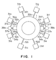
- FIG. 1 is a structural diagram of a first embodiment of a remote maintenance apparatus of the present invention.
- FIG. 2 consists of structural diagrams of a laser path switcher, wherein FIG. 2A shows an unswitched laser path and FIG. 2B shows a switched laser path.
- FIG. 3 shows an embodiment of a laser beam combiner.
- FIG. 4 shows a second embodiment of a laser beam combiner.
- FIG. 5 shows a third embodiment of a laser beam combiner.
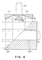
- FIG. 6 shows a fourth embodiment of a laser beam combiner.
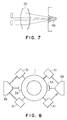
- FIG. 7 is an explanatory diagram of an example of working with the combined laser beam.
- FIG. 8 shows a second embodiment of a remote maintenance apparatus of the present invention.
- FIG. 9 is a structural diagram of a conventional fusion device.
- FIG. 10 is an explanatory diagram of a laser processing device for a cooling piping system of an impurity removal device of the conventional fusion device shown in FIG. 9.
- FIG. 11 is a structural diagram of a remote maintenance system for cutting or welding cooling piping in a conventional impurity removal device.
- FIG. 12 is an explanatory diagram of a method of disassembling a vacuum wall of a conventional fusion device.
- FIG. 13 is a perspective view of a high-power type of fusion device.
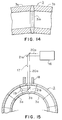
- FIG. 14 is a partial cross-sectional view of a joint portion of a segment of the vacuum wall of a fusion device.
- FIG. 15 is a structural diagram of a remote cutting and welding device inserted between segments of a conventional vacuum wall.
- FIG. 16 is an explanatory diagram of a laser work head.
- FIG. 17 is an explanatory diagram of a laser robot in a state wherein it is welding between segments.
- FIG. 18 is a structural diagram of a remote maintenance apparatus of a conventional fusion device.
- Laser beam generators 31a, 31b, ..., and 31h for cutting or welding cooling piping are arranged around the entire periphery of a fusion device 1 corresponding to installation locations of cooling piping of an impurity removal device, as shown in FIG. 1.
- Each of the laser beam generators 31a, 31b, ..., 31h is connected to a corresponding laser beam transmission system 32a, 32b, ..., 32h for guiding a laser beam generated from that laser beam generator into the corresponding cooling piping.
- Two maintenance ports 33a and 33b are provided on the outer periphery of a diameter of the fusion device 1, to allow periodic maintenance of the impurity removal device.
- Laser beam outlet ports of the laser beam generators 31a, 31b, 31e, and 31f on either side of the maintenance ports 33a and 33b are provided with corresponding optical path switchers 34a, 34b, 34e, and 34f.
- Each of the optical path switchers 34a, 34b, 34e, and 34f comprises a full mirror 35, a mirror holder 36 that supports the full mirror 35, and a mirror movement mechanism that is a screw mechanism. If a laser beam 31 a1 generated from the laser beam generator 31a is to be transmitted along a laser beam transmission pipe in order to guide it into the cooling piping of the impurity removal device, the full mirror 35 is held at an inoperative location as shown in FIG. 2A.
- the full mirror 35 is moved to the location shown in FIG. 2B, to send the laser beam 31a1 into a beam combiner transmission system 37a (shown in FIG. 1).
- Beam combiner transmission systems 37a and 37b are connected to a laser beam combiner 38a, and beam combiner transmission systems 37e and 37f are connected to a beam combiner 38b, as shown in FIG. 1.
- Each of the beam combiner transmission systems 37a and 37b is provided with a laser beam transmission system 39a or 39b that transmits a laser beam through the maintenance port 33a or 33b to a work head inserted within the vacuum wall.
- Each of the laser beam combiners 38a and 38b has a full mirror 40 in the shape of a triangular prism, as shown in FIG. 3.
- Laser beams 41a and 41b directed at the full mirror 40 and incident thereon from opposite sides thereof are reflected into the same direction by corresponding mirror surfaces 40a and 40b of the full mirror 40.
- the two beams that have been reflected into the same direction can then be manipulated as a single combined beam.
- these laser beam combiners 38a and 38b can be used to combine the two beams by the full mirror of triangular prism shape alone, and the combination efficiency (the ratio of the output power of the combined beam to the sum of the powers of the individual laser beams) is also good--affected only by deterioration in the absorption coefficient of the mirror surfaces of the full mirror.
- the operation is as follows. First the cutting/welding position is determined to see which of the two maintenance ports 33a and 33b is closer. Assuming that maintenance port 33a is the closer, the two laser beam generators 31a and 31b on either side of that port are then activated and also the optical path switchers 34a and 34b are operated, so that the laser beams generated by the laser beam generators 31a and 31b are guided to the laser beam combiner 38a via the beam combiner transmission systems 37a and 37b.
- the two laser beams are combined by the laser beam combiner 38a to increase the laser power, the combined beam is supplied to the work head within the vacuum wall, through the maintenance port 33a via the laser beam transmission system 39a, and the vacuum wall is cut or welded thereby.
- the combined laser beam that is introduced into the vacuum wall has a power close to the sum of the powers of the laser beams generated by the laser beam generators 31a and 31b, and thus a laser power can be obtained that is far higher than that produced by the individual laser beam generators 31a, 31b, ..., 31h provided for the cooling piping.
- This can remove the various problems involved with using a dedicated laser to cut or weld a vacuum wall of a thickness far greater than that of the cooling piping.
- a laser beam combiner of a type that combines three laser beams is shown in FIG. 4 and a similar one that combines four laser beams is shown in FIG. 5.
- the laser beam combiner of FIG. 4 presents a full mirror 42 of the shape of a triangular pyramid with a circular base.
- laser beams 43a, 43b, and 43c that are incident on the full mirror 42 from three directions parallel to the plane of the paper are reflected by corresponding mirror surfaces 42a, 42b, and 42c into a direction perpendicular to the plane of the paper and are combined.
- laser beams 45a, 45b, 45c, and 45d that are incident on a full mirror 44, shown in FIG. 5, from four directions parallel to the plane of the paper can be converted by corresponding mirror surfaces 44a, 44b, 44c, and 44d into a single laser beam in a direction perpendicular to the plane of the paper.
- Another embodiment of the laser beam combiner is provided with a first full mirror 50 of a circular pyramid shape and a second full mirror 51 of a doughnut shape having a slanting mirror surface 51a in a lower surface thereof, as shown in FIG. 6.
- a third full mirror 52 wherein one end surface thereof forms a mirror surface 52a at an angle with respect to the mirror surface 51a, the third mirror 52 also having a central aperture 52b extending in a direction perpendicular to the axis of the first mirror 50.
- first incident laser beam 53 strikes the first mirror 50, it is converted into an annular laser beam by the first mirror 50 and the second mirror 51, and the annular laser beam is converted to strike the mirror surface 52a of the third mirror 52, which has a central aperture therein extending in an direction perpendicular to the axis of the first mirror 50.
- second incident laser beam 54 is incident through the central aperture 52b of the third mirror 52, the second incident laser beam 54 is concentric with the annular laser beam whose direction has been converted as described above, to obtain a combined laser beam that has a roughly circular cross-section.
- the laser beam combiner of the above configuration does require three full mirrors, but the combined laser beam obtained thereby has a circular cross-section and the characteristics of the focused beam obtained after it is incident on a focusing optical system are good.
- each of the original beams generates a focusing peak so that, as shown in FIG. 7, a combination of two beams generates two peaks after the focusing. If this feature is utilized, a broad weld portion 56 can be obtained therefrom, to enable specific laser working.
- a second embodiment of the present invention shown in FIG. 8 is provided with four laser beam generators 31, two laser beam combiners, and the laser beams combined by the laser beam combiners are guided into the vacuum wall through two maintenance ports 33 to provide cutting or welding between the segments. It should be obvious to those skilled in the art that, with an even bigger fusion device, eight or more laser beam generators could be provided and three or more laser beams could be combined from these laser beam generators, to obtain effects similar to those described above.
Landscapes
- Physics & Mathematics (AREA)
- Optics & Photonics (AREA)
- Engineering & Computer Science (AREA)
- Plasma & Fusion (AREA)
- Mechanical Engineering (AREA)
- General Engineering & Computer Science (AREA)
- High Energy & Nuclear Physics (AREA)
- Laser Beam Processing (AREA)
- Lasers (AREA)
Applications Claiming Priority (2)
| Application Number | Priority Date | Filing Date | Title |
|---|---|---|---|
| JP107826/92 | 1992-04-27 | ||
| JP4107826A JP2807371B2 (ja) | 1992-04-27 | 1992-04-27 | 遠隔保全装置 |
Publications (2)
| Publication Number | Publication Date |
|---|---|
| EP0567929A1 true EP0567929A1 (fr) | 1993-11-03 |
| EP0567929B1 EP0567929B1 (fr) | 1996-08-21 |
Family
ID=14469022
Family Applications (1)
| Application Number | Title | Priority Date | Filing Date |
|---|---|---|---|
| EP93106557A Expired - Lifetime EP0567929B1 (fr) | 1992-04-27 | 1993-04-22 | Appareil de maintenance à distance |
Country Status (4)
| Country | Link |
|---|---|
| US (1) | US5444213A (fr) |
| EP (1) | EP0567929B1 (fr) |
| JP (1) | JP2807371B2 (fr) |
| DE (1) | DE69304123T2 (fr) |
Cited By (1)
| Publication number | Priority date | Publication date | Assignee | Title |
|---|---|---|---|---|
| CN104400276A (zh) * | 2014-09-02 | 2015-03-11 | 中国科学院等离子体物理研究所 | 一种用于核聚变装置真空室内部管路遥操作切焊的机构 |
Families Citing this family (7)
| Publication number | Priority date | Publication date | Assignee | Title |
|---|---|---|---|---|
| DE19910146B4 (de) * | 1998-03-31 | 2006-08-10 | Bakal, Semen, Dr. | Vorrichtung zur Erzeugung von Kollisionen gegenläufiger Ionenbündel |
| US6266359B1 (en) | 1999-09-02 | 2001-07-24 | Alphamicron, Inc. | Splicing asymmetric reflective array for combining high power laser beams |
| US8432943B2 (en) * | 2007-02-22 | 2013-04-30 | The Boeing Company | Monolithic fiber laser beam combiner |
| CH700083A2 (de) * | 2008-12-03 | 2010-06-15 | Cosmobrain Ag | Verfahren und Vorrichtung zum Herstellen von Rohrabschnitten. |
| DE102010047917A1 (de) * | 2010-10-08 | 2012-04-12 | Jenoptik Automatisierungstechnik Gmbh | Vorrichtung zur simultanen Umfangsbearbeitung eines Werkstückes mit Laserstrahlen |
| US8599487B2 (en) * | 2011-11-21 | 2013-12-03 | Coherent, Inc. | Beam-combiner for fiber-delivered laser-beams of different wavelengths |
| JP5574354B2 (ja) | 2012-03-09 | 2014-08-20 | 株式会社トヨコー | 塗膜除去方法及びレーザー塗膜除去装置 |
Citations (4)
| Publication number | Priority date | Publication date | Assignee | Title |
|---|---|---|---|---|
| FR1561258A (fr) * | 1968-01-15 | 1969-03-28 | ||
| EP0130799A1 (fr) * | 1983-06-29 | 1985-01-09 | Integrated Laser Systems Limited | Appareil pour le soudage des tubes ou semblables par laser |
| DE3642386A1 (de) * | 1985-12-12 | 1987-08-13 | Mitsubishi Electric Corp | Dual-polarisierungs-, dual-frequenz-schneidmaschine |
| US4953950A (en) * | 1987-04-30 | 1990-09-04 | Yoshiaki Arata | Apparatus for producing ultra-high power ultra-high density laser beam |
Family Cites Families (14)
| Publication number | Priority date | Publication date | Assignee | Title |
|---|---|---|---|---|
| JPS5969979A (ja) * | 1982-10-15 | 1984-04-20 | Hitachi Ltd | レ−ザ光源装置 |
| JPS607592A (ja) * | 1983-06-24 | 1985-01-16 | シャープ株式会社 | 電子式キャッシュレジスタ |
| US4694136A (en) * | 1986-01-23 | 1987-09-15 | Westinghouse Electric Corp. | Laser welding of a sleeve within a tube |
| JPS62183992A (ja) * | 1986-02-10 | 1987-08-12 | Mitsubishi Heavy Ind Ltd | レ−ザ加工装置 |
| JPS6347714A (ja) * | 1986-08-14 | 1988-02-29 | Yoshiaki Arata | レ−ザビ−ム重畳方法 |
| US4701018A (en) * | 1986-10-02 | 1987-10-20 | Greyhawk Systems, Inc. | Apparatus for mounting two lasers to produce parallel or colinear beams |
| DE3743902A1 (de) * | 1986-12-26 | 1988-07-07 | Mitsubishi Electric Corp | Laserbearbeitungsvorrichtung |
| JPS63165092A (ja) * | 1986-12-26 | 1988-07-08 | Mitsubishi Electric Corp | レ−ザ加工装置 |
| JPS63165094A (ja) * | 1986-12-26 | 1988-07-08 | Mitsubishi Electric Corp | レ−ザ加工装置 |
| DE3709351A1 (de) * | 1987-03-21 | 1988-09-29 | Heraeus Gmbh W C | Strahlfuehrungsoptik fuer laserstrahlung |
| JPS63273582A (ja) * | 1987-05-01 | 1988-11-10 | Toshiba Corp | レ−ザ加工機 |
| JPH01245992A (ja) * | 1988-03-25 | 1989-10-02 | Ind Res Inst Japan | 多波長レーザー加工装置 |
| US5138491A (en) * | 1988-08-26 | 1992-08-11 | Fuji Photo Film Co., Ltd. | Beam-combining laser beam source device |
| JPH04344884A (ja) * | 1991-05-22 | 1992-12-01 | Nippon Steel Corp | レーザビーム合成光学装置 |
-
1992
- 1992-04-27 JP JP4107826A patent/JP2807371B2/ja not_active Expired - Fee Related
-
1993
- 1993-04-22 EP EP93106557A patent/EP0567929B1/fr not_active Expired - Lifetime
- 1993-04-22 DE DE69304123T patent/DE69304123T2/de not_active Expired - Fee Related
- 1993-04-26 US US08/051,883 patent/US5444213A/en not_active Expired - Fee Related
Patent Citations (4)
| Publication number | Priority date | Publication date | Assignee | Title |
|---|---|---|---|---|
| FR1561258A (fr) * | 1968-01-15 | 1969-03-28 | ||
| EP0130799A1 (fr) * | 1983-06-29 | 1985-01-09 | Integrated Laser Systems Limited | Appareil pour le soudage des tubes ou semblables par laser |
| DE3642386A1 (de) * | 1985-12-12 | 1987-08-13 | Mitsubishi Electric Corp | Dual-polarisierungs-, dual-frequenz-schneidmaschine |
| US4953950A (en) * | 1987-04-30 | 1990-09-04 | Yoshiaki Arata | Apparatus for producing ultra-high power ultra-high density laser beam |
Non-Patent Citations (3)
| Title |
|---|
| MILLS S. F., LOVING A., IRVING M.: "THE DESIGN, DEVELOPMENT AND USE OF PIPE CUTTING TOOLS FOR REMOTE HANDLING IN JET.", PROCEEDINGS OF THE IEEE/NPSS SYMPOSIUM ON FUSION ENGINEERING. SAN DIEGO, SEPT. 30 - OCT. 3, 1991., NEW YORK, IEEE., US, vol. 01., 30 September 1991 (1991-09-30), US, pages 559 - 562., XP000308364, ISBN: 978-0-7803-0132-0 * |
| PATENT ABSTRACTS OF JAPAN vol. 10, no. 368 (M-543)(2425) 9 December 1986 & JP-A-61 162 281 ( NIPPON STEEL ) 22 July 1986 * |
| PATENT ABSTRACTS OF JAPAN vol. 13, no. 130 (M-808)(3478) 30 March 1989 & JP-A-63 299 883 ( MITSUBISHI ) 7 December 1988 * |
Cited By (2)
| Publication number | Priority date | Publication date | Assignee | Title |
|---|---|---|---|---|
| CN104400276A (zh) * | 2014-09-02 | 2015-03-11 | 中国科学院等离子体物理研究所 | 一种用于核聚变装置真空室内部管路遥操作切焊的机构 |
| CN104400276B (zh) * | 2014-09-02 | 2016-02-17 | 中国科学院等离子体物理研究所 | 一种用于核聚变装置真空室内部管路遥操作切焊的机构 |
Also Published As
| Publication number | Publication date |
|---|---|
| DE69304123T2 (de) | 1997-02-06 |
| JP2807371B2 (ja) | 1998-10-08 |
| EP0567929B1 (fr) | 1996-08-21 |
| DE69304123D1 (de) | 1996-09-26 |
| US5444213A (en) | 1995-08-22 |
| JPH05305463A (ja) | 1993-11-19 |
Similar Documents
| Publication | Publication Date | Title |
|---|---|---|
| US5444213A (en) | Remote maintenance method and system for a fusion reactor | |
| Sanderson et al. | Advanced welding processes for fusion reactor fabrication | |
| US7982935B2 (en) | Mirror positioning apparatus for use in beam switching | |
| EP0483964A2 (fr) | Tube accélérateur supraconducteur et méthode pour le produire | |
| Erckmann et al. | ECRH and ECCD with high power gyrotrons at the stellarators W7-AS and W7-X | |
| US6429403B1 (en) | Supporting grid welding apparatus | |
| US6614037B2 (en) | Electron beam irradiating apparatus | |
| CA1189576A (fr) | Appareil pour le decoupage au rayon laser, et methode connexe | |
| RU2756175C1 (ru) | Роботизированный лазерный комплекс и способ демонтажа металлоконструкций аэс | |
| US8320426B2 (en) | Apparatus for selectively distributing energy from a laser beam | |
| AU7080487A (en) | C.W. multi-slab laser | |
| US6291795B1 (en) | Unfocused laser beam delivery system | |
| Prater et al. | A design study for the ECH launcher for ITER | |
| Hallada et al. | Chemical oxygen-iodine laser (COIL) for the dismantlement of nuclear facilities | |
| Erckmann et al. | The 10 MW ECRH and CD System for W7‐X | |
| JP6850057B2 (ja) | レーザー光路変更装置 | |
| Crea | Tokamak, fusion reactor device: Welding and joining for plasma facing components | |
| CN215941838U (zh) | 高功率激光光学系统 | |
| WO2023159205A1 (fr) | Composants optiques à base de plasma et de gaz pour contrôler les dommages causés par les rayonnements | |
| KR102391624B1 (ko) | 이동식 레이저 용접 장치 | |
| Erckmann et al. | The 10 MW, CW ECRH System For W7‐X: Status And First Integrated Tests | |
| Laqua et al. | The steady-state ECRH-system at wendelstein7-X | |
| Jones | Developments in joining processes for structural steel applications | |
| Gormezano | RF systems for heating and current drive in fusion experiments | |
| Callis et al. | Status of the DIII-D 110 GHz ECH system |
Legal Events
| Date | Code | Title | Description |
|---|---|---|---|
| PUAI | Public reference made under article 153(3) epc to a published international application that has entered the european phase |
Free format text: ORIGINAL CODE: 0009012 |
|
| 17P | Request for examination filed |
Effective date: 19930422 |
|
| AK | Designated contracting states |
Kind code of ref document: A1 Designated state(s): DE FR GB |
|
| 17Q | First examination report despatched |
Effective date: 19950411 |
|
| GRAH | Despatch of communication of intention to grant a patent |
Free format text: ORIGINAL CODE: EPIDOS IGRA |
|
| GRAA | (expected) grant |
Free format text: ORIGINAL CODE: 0009210 |
|
| GRAH | Despatch of communication of intention to grant a patent |
Free format text: ORIGINAL CODE: EPIDOS IGRA |
|
| AK | Designated contracting states |
Kind code of ref document: B1 Designated state(s): DE FR GB |
|
| REF | Corresponds to: |
Ref document number: 69304123 Country of ref document: DE Date of ref document: 19960926 |
|
| ET | Fr: translation filed |
Free format text: CORRECTIONS |
|
| PLBE | No opposition filed within time limit |
Free format text: ORIGINAL CODE: 0009261 |
|
| 26N | No opposition filed | ||
| PGFP | Annual fee paid to national office [announced via postgrant information from national office to epo] |
Ref country code: GB Payment date: 19990421 Year of fee payment: 7 |
|
| PG25 | Lapsed in a contracting state [announced via postgrant information from national office to epo] |
Ref country code: GB Free format text: LAPSE BECAUSE OF NON-PAYMENT OF DUE FEES Effective date: 20000422 |
|
| GBPC | Gb: european patent ceased through non-payment of renewal fee |
Effective date: 20000422 |
|
| PGFP | Annual fee paid to national office [announced via postgrant information from national office to epo] |
Ref country code: DE Payment date: 20020502 Year of fee payment: 10 |
|
| PG25 | Lapsed in a contracting state [announced via postgrant information from national office to epo] |
Ref country code: DE Free format text: LAPSE BECAUSE OF NON-PAYMENT OF DUE FEES Effective date: 20031101 |
|
| PGFP | Annual fee paid to national office [announced via postgrant information from national office to epo] |
Ref country code: FR Payment date: 20050408 Year of fee payment: 13 |
|
| REG | Reference to a national code |
Ref country code: FR Ref legal event code: ST Effective date: 20061230 |
|
| PG25 | Lapsed in a contracting state [announced via postgrant information from national office to epo] |
Ref country code: FR Free format text: LAPSE BECAUSE OF NON-PAYMENT OF DUE FEES Effective date: 20060502 |