EP0568057A2 - Kassette mit dünnwandigem Deckel - Google Patents
Kassette mit dünnwandigem Deckel Download PDFInfo
- Publication number
- EP0568057A2 EP0568057A2 EP93106953A EP93106953A EP0568057A2 EP 0568057 A2 EP0568057 A2 EP 0568057A2 EP 93106953 A EP93106953 A EP 93106953A EP 93106953 A EP93106953 A EP 93106953A EP 0568057 A2 EP0568057 A2 EP 0568057A2
- Authority
- EP
- European Patent Office
- Prior art keywords
- cover
- wall
- upper wall
- videocassette
- side walls
- Prior art date
- Legal status (The legal status is an assumption and is not a legal conclusion. Google has not performed a legal analysis and makes no representation as to the accuracy of the status listed.)
- Withdrawn
Links
Images


Classifications
-
- G—PHYSICS
- G11—INFORMATION STORAGE
- G11B—INFORMATION STORAGE BASED ON RELATIVE MOVEMENT BETWEEN RECORD CARRIER AND TRANSDUCER
- G11B23/00—Record carriers not specific to the method of recording or reproducing; Accessories, e.g. containers, specially adapted for co-operation with the recording or reproducing apparatus ; Intermediate mediums; Apparatus or processes specially adapted for their manufacture
- G11B23/02—Containers; Storing means both adapted to cooperate with the recording or reproducing means
- G11B23/04—Magazines; Cassettes for webs or filaments
- G11B23/08—Magazines; Cassettes for webs or filaments for housing webs or filaments having two distinct ends
- G11B23/087—Magazines; Cassettes for webs or filaments for housing webs or filaments having two distinct ends using two different reels or cores
- G11B23/08707—Details
- G11B23/08721—Brakes for tapes or tape reels
-
- G—PHYSICS
- G11—INFORMATION STORAGE
- G11B—INFORMATION STORAGE BASED ON RELATIVE MOVEMENT BETWEEN RECORD CARRIER AND TRANSDUCER
- G11B23/00—Record carriers not specific to the method of recording or reproducing; Accessories, e.g. containers, specially adapted for co-operation with the recording or reproducing apparatus ; Intermediate mediums; Apparatus or processes specially adapted for their manufacture
- G11B23/02—Containers; Storing means both adapted to cooperate with the recording or reproducing means
- G11B23/04—Magazines; Cassettes for webs or filaments
- G11B23/08—Magazines; Cassettes for webs or filaments for housing webs or filaments having two distinct ends
- G11B23/087—Magazines; Cassettes for webs or filaments for housing webs or filaments having two distinct ends using two different reels or cores
- G11B23/08707—Details
- G11B23/08728—Reels or cores; positioning of the reels in the cassette
-
- G—PHYSICS
- G11—INFORMATION STORAGE
- G11B—INFORMATION STORAGE BASED ON RELATIVE MOVEMENT BETWEEN RECORD CARRIER AND TRANSDUCER
- G11B23/00—Record carriers not specific to the method of recording or reproducing; Accessories, e.g. containers, specially adapted for co-operation with the recording or reproducing apparatus ; Intermediate mediums; Apparatus or processes specially adapted for their manufacture
- G11B23/02—Containers; Storing means both adapted to cooperate with the recording or reproducing means
- G11B23/04—Magazines; Cassettes for webs or filaments
- G11B23/08—Magazines; Cassettes for webs or filaments for housing webs or filaments having two distinct ends
- G11B23/087—Magazines; Cassettes for webs or filaments for housing webs or filaments having two distinct ends using two different reels or cores
- G11B23/08707—Details
- G11B23/08785—Envelopes
Definitions
- the present invention relates to molded parts. More particularly, the present invention relates to molded cassette parts.
- Videocassettes typically include a housing having a reel of magnetic recording tape called the supply reel and a take-up reel. One end of the tape on the supply reel is attached to the take-up reel.
- the housing typically includes a lower half, called the base 10, and an upper half, called the cover 12.
- a door (not shown), which protects the exposed length of tape 16 running between the supply reel 18 and the take-up reel 20 when the cassette is not in use, is attached to the cover 12.
- VCR videocassette recorder
- the tape 16 follows a prescribed path from the supply reel 18, over various tape guides, out of the housing, across a planar area called the left bridge 22, across an open area 24 where the tape 16 is unsupported, to a planar area called the right bridge 26, and back into the housing to the take-up reel 20.
- the long side of the cassette on which the bridges 22, 26 are located is the front 28 of the cassette, and the long side opposite the front side of the cassette is the rear 30 of the cassette.
- the end of the cassette nearest the supply reel 18 is the left end 32 of the cassette, and the end of the cassette nearest the take-up reel 20 is the right end 34.
- reel brakes 36, 38 which pivot on pins 40, 42, which typically are molded as part of the base 10.
- the reel brakes 36, 38 keep the reels 18, 20 from unrolling the tape 16 when the cassette is out the VCR.
- Other safety devices signal the VCR that the end of the tape 16 has been reached, thereby preventing damage to the recorded material.
- the base 10 and cover 12 fit together to enclose the tape reels 18, 20, along with the other internal parts, to exclude contaminants and protect the tape 16 from damage. Alignment of the cover 12 with the base 10 is assured by screw bosses 44 in the base 10 which mate with corresponding bosses 46 in the cover 12, as shown in Figure 2.
- Videocassette housings typically are injection molded using a synthetic resin such as polystyrene or acrylonitrile-butadiene-styrene (ABS). Molds for the base 10 and cover 12 are typically designed to pull apart vertically, with one half of the mold forming substantially all of the internal parts of the base 10 or cover 12, and the other half forming the outside surfaces of the part. Since videocassette housings have large wall areas, reducing wall thickness is important to minimizing injection molding costs. Wall thickness contributes to part cost not only through the quantity of material used in the part, but also through the time required to cool the part before ejection from the mold.
- ABS acrylonitrile-butadiene-styrene
- the spring 54 is typically formed from a thin strip of metal which is bent slightly away from the cover surface 56 at crimps 58 to press downward on the centers of reels 18, 20 when the cover 12 is fitted onto the base 10.
- the reel spring 54 is typically held in place by bosses 60, which pass through holes in the spring 54 and are pressed down with a heated riveting tool to form expanded heads which press the spring 54 against the cover surface 56. Because the ends 62 of the spring 54 press against the centers of the reels 18, 20, the cover surface 56 must have sufficient structural strength, and hence sufficient wall thickness, to sustain this spring force without excessive outward bowing or breakage.
- Another factor in determining wall thickness is resin flow during injection molding.
- the various parts of the mold serve not only to determine the size and shape of the part being molded, but also act as passages through which the molten plastic must flow to reach other parts of the mold. If a wall section is too thin, the portion of the mold forming that wall section will be correspondingly thin, thereby restricting flow, and causing excessive reduction in injection pressure at points farther from the point of injection, or gate. As a result, the injection pressure may have to be raised, or the injection time may have to be lengthened, or both.
- U.S. Patent No. 4,706,149 describes the ejection difficulties which can arise when injection pressures are high. Additionally, polymeric materials which are forced to flow through very thin channels at the high shear rates produced by high injection pressures often undergo excessive orientation of the polymer chains, which can weaken the part and directionally vary shrink rates, which can, in turn, lead to warping.
- cassette bases and covers have sections having a variety of shapes and thicknesses, these various sections will require different times to cool during injection molding.
- the overall cooling time required for the part will be determined by the slowest cooling section, called the "critical section for cooling.” Further, as the cooling time for some sections is shortened by thinning, it is possible that another section may become the critical section. Therefore, thinning of only the wall sections may not be sufficient to significantly shorten the overall cooling time for the part.
- the videocassette cover according to the present invention includes an upper wall with a mounting device for receiving a reel spring.
- Two opposing side walls are perpendicular to the upper wall, a front wall is perpendicular to the upper wall and the side walls, and a rear wall opposes the front wall and is perpendicular to the upper wall and the side walls.
- a first portion of conventional thickness is located substantially in the center of the cover upper wall and is spaced from the side, front, and rear walls. The first portion extends over an area which encompasses at least the area contacted by the reel spring and can be cross-shaped.
- a second portion of reduced thickness is located substantially adjacent the side, front, and rear walls.
- the upper wall has a transition area of varying thickness located between the first and second portions.
- the transition area varies uniformly from the thickness of the first portion to the thickness of the second portion and extends between the first and second portions at only the sides of the first portion that run generally in the same direction as the side walls of the cover.
- the cover side walls combine with the rear wall to form rear corners of the cover and the thickness of the upper wall in the rear corners of the cover is greater than the thickness of the remainder of the second portion located substantially adjacent the side, front, and rear walls to form a thicker corner pad.
- Figure 1 is a plan view of the base of a known videocassette.
- Figure 2 is a plan view of a known cover of the videocassette of Figure 1.
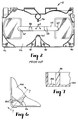
- Figure 3 is a plan view of a cover of a videocassette according to the present invention.
- Figure 4 is a cross-sectional view of the videocassette taken along line 4-4 of Figure 3.
- Figure 5 is a cross-sectional view of the videocassette taken along line 5-5 of Figure 3.
- Figure 6 is an enlarged view of the corner pad of Figure 3.
- Figure 7 is a cross-sectional view taken through line 7-7 of Figure 6.
- a videocassette cover includes an upper wall including a mounting device for receiving a reel spring, two opposing side walls perpendicular to the upper wall, a front wall perpendicular to the upper wall and the side walls, and a rear wall opposing the front wall and perpendicular to the upper wall and the side walls.
- the side walls define the left and right ends 32, 34 of the cassette while the respective front and rear walls define the front 28 and rear 30 of the cassette.
- a portion of the cover, area 164 is of conventional wall thickness, which is about 2.0 mm (0.08 in).
- This thicker area 164 is shown as cross-shaped, although other shapes, such as rectangular, also can be used and can extend beyond, within, or to the label indentation 160 edges.
- Another portion of the cover, area 166 has a reduced wall thickness of about 1.4-1.5 mm (0.055-0.060 in), compared to a wall thickness in area 164 and in this area in known VHS cassettes of about 2.0 mm.
- the thinnest section of the cover top wall 56 are in the areas 168 located to the left and right of the area 164.
- the wall thickness of the areas 168 is further reduced by the depth of the label indentation 160, which can be as high as 0.53 mm.
- edges 170 of the area 164 extend slightly beyond the edges 172 of the label indentation area 160, so that the area 164 slightly overlaps the label indentation area 160 in the front-to-back direction.
- a sectional view of this overlap is shown in Figure 5.
- the amount of overlap t o is approximately equal to wall thickness t w .
- This overlap enhances the structural strength of the cover top wall 56 and facilitates the flow of molding material during injection.
- the chances of sink marks or other surface defects appearing as a result of sudden changes in wall thickness are reduced.
- the edge 170 is portrayed as forming sharp corners in Figure 5, it could also form a more gentle transition, such as by being sloping or rounded.
- the area 164 need not extend beyond the area defined by the label indentation 160, provided a suitable transition is made between the area 164 and the thinner area 166.
- the area 164 need not overlap the label indentation area 160 in the left-to-right direction the way that it does in the front-to-back direction.
- the transition areas 174, 176, 178, 180, 182 connect the area 164 with the areas 166 as shown in Figure 3.
- Extensions 184 of the area 164 provide additional support of the spring 54 to allow springs used in conventional cassettes to be used in the thinner wall cassette of the present invention, without changing the location or bend angles of the crimps 58. Extensions 184 give the area 164 its cross-shaped configuration.
- the area 164 also provides improved flow of molding material during injection. As shown in Figure 3, when the cover 12 is produced by injection molding, the gate 162 is typically located such that molding material must first flow through the area 164 before reaching the other parts of the mold. It has been found that by providing an area of conventional wall thickness, such as the area 164 connecting the gate 162 with the rest of the mold, the required injection pressure can be significantly reduced, thereby improving both manufacturability and part quality.
- An additional feature of the present invention is the use of sloping transition sections between the thicker areas and the thinner areas.
- the transition areas 174, 176, 178, 180, 182 provide a gradual change in wall thickness between the area 164 and the area 166, as shown in Figure 3. If the transition from a wall thickness of 1.46 mm (0.058 inches) (in the area 164) to a wall thickness of 1.1 mm (0.043 inches) (in the area 168) is made over a distance of about 7.6 mm (0.30 inches), the appearance of the outside of the cover 12, especially in the label area 160, remains unaffected. This indicates that the flow of molding material during injection is not noticeably disrupted.
- transition from a first wall thickness to a second wall thickness which is 75% of the first wall thickness occurs over a distance of about five times the first wall thickness, no noticeable defects occur, even after subjecting the cassette to an environmental test of holding the cassette at 71°C (160° F) for 3 days.
- the transition areas 174-182 extend between the thicker area 164 and the thinner area 166 at only the sides of the first portion that run generally in the same direction as the side walls of the cover, as shown in Figure 3.
- the range of distances over which the transition from the area 164 to the area 168 can be made depends upon the extent to which the outside surface can be treated, for example, with texturing to hide any defects. Making the transition over a shorter distance tends to create more severe surface defects the hiding of which, in turn, requires deeper texturing. If deeper texturing is not permitted, then the transition must be more gradual, occurring over a longer distance, to reduce the severity of surface blemishing to be covered. Depending upon the depth of texturing permitted in label indentation area 160, the transition in wall thickness can take place in as little as 1.27 mm (0.05 inches), if deep texturing is permitted on the outside surface, or as much as 10.1 mm (0.40 inches), if only shallower texturing is permitted.
- Each side wall of the cover 12 combines with the rear wall to form a rear corner of the cover 12.
- the thickness of the upper wall in the rear corners of the cover 12 is greater than the thickness of the remainder of the thinner areas 166 to form a thicker corner pad 186, with the thicker area on the inside of the cover as shown in Figures 3, 6, and 7.
- the thickness of the corner pads 186 could equal the thickness of the thicker area 164.
- the corner pads 186 extend toward the screw bosses 46 and are spaced from the screw bosses 46 as best shown in Figures 6 and 7.
- the corner pads 186 eliminate visual defects in the cover caused by air entrapment due to the accelerating flow of material over the top and rear label surfaces of the cover 12 to the side walls. Increasing the wall thickness of the corner pads 186 decelerates the melt front of the mold material to allow proper venting and prevent air entrapment.
- a triangular strengthening brace 188 can be located on at least one side wall of the cover 12.
- the triangular strengthening brace 188 improves the surface quality of the outside wall of the cover 12.
- the triangular strengthening brace 188 can be designed to avoid leaving sink marks on the outside surface of the outside wall.
- Another type of defect which has been reduced by the triangular strengthening brace 188 is the appearance of weld lines. Weld lines occur when, during molding, plastic flows to an area by two different paths with the flow fronts from each path meeting to form a weld line, which remains visible on the finished part.
- Another closely related surface defect which is reduced by the triangular strengthening brace 188 is the flow line, which is a wavy line caused by certain unsatisfactory flow patterns.
- a further improvement to the cover is the center insert 126, which includes walls 134, 136, as shown in Figure 2.
- the center insert 126 serves primarily to hold a reel brake lever and to provide reinforcement to the outside wall 146 of the cover 12.
- These walls 134, 136 also serve as flow channels for conveying molding material to the outside wall during injection.
Landscapes
- Injection Moulding Of Plastics Or The Like (AREA)
Applications Claiming Priority (2)
| Application Number | Priority Date | Filing Date | Title |
|---|---|---|---|
| US87747792A | 1992-05-01 | 1992-05-01 | |
| US877477 | 2001-06-08 |
Publications (2)
| Publication Number | Publication Date |
|---|---|
| EP0568057A2 true EP0568057A2 (de) | 1993-11-03 |
| EP0568057A3 EP0568057A3 (de) | 1994-12-21 |
Family
ID=25370051
Family Applications (1)
| Application Number | Title | Priority Date | Filing Date |
|---|---|---|---|
| EP93106953A Withdrawn EP0568057A3 (de) | 1992-05-01 | 1993-04-29 | Kassette mit dünnwandigem Deckel. |
Country Status (2)
| Country | Link |
|---|---|
| EP (1) | EP0568057A3 (de) |
| JP (1) | JPH0596964U (de) |
Cited By (1)
| Publication number | Priority date | Publication date | Assignee | Title |
|---|---|---|---|---|
| EP0827149A1 (de) * | 1996-08-27 | 1998-03-04 | TDK Corporation | Bandkasette |
Family Cites Families (6)
| Publication number | Priority date | Publication date | Assignee | Title |
|---|---|---|---|---|
| JPS571343Y2 (de) * | 1977-11-18 | 1982-01-09 | ||
| JPS5616886U (de) * | 1979-07-17 | 1981-02-14 | ||
| US4512534A (en) * | 1982-08-12 | 1985-04-23 | T/B & H Home Video | Cassette reel lock |
| DE8335294U1 (de) * | 1983-12-09 | 1984-03-22 | Basf Ag, 6700 Ludwigshafen | Andruckfeder für Bandkassetten und Bandkassetten damit |
| DE8807993U1 (de) * | 1988-06-22 | 1988-08-11 | Agfa-Gevaert Ag, 5090 Leverkusen | Magnetbandkassette |
| JPH0276183A (ja) * | 1988-09-12 | 1990-03-15 | Sony Corp | テープカセット |
-
1993
- 1993-04-29 EP EP93106953A patent/EP0568057A3/de not_active Withdrawn
- 1993-04-30 JP JP2297693U patent/JPH0596964U/ja active Pending
Cited By (3)
| Publication number | Priority date | Publication date | Assignee | Title |
|---|---|---|---|---|
| EP0827149A1 (de) * | 1996-08-27 | 1998-03-04 | TDK Corporation | Bandkasette |
| US5946170A (en) * | 1996-08-27 | 1999-08-31 | Tdk Corporation | Tape cassette with selected wall thicknesses |
| KR100292754B1 (ko) * | 1996-08-27 | 2001-07-12 | 사또 히로시 | 테이프카세트 |
Also Published As
| Publication number | Publication date |
|---|---|
| JPH0596964U (ja) | 1993-12-27 |
| EP0568057A3 (de) | 1994-12-21 |
Similar Documents
| Publication | Publication Date | Title |
|---|---|---|
| US5472655A (en) | Method and apparatus for molding magnetic tape cassette | |
| EP0160538A2 (de) | Biegsame Magnetplattenkassetten und Verfahren um solche Kassetten herzustellen | |
| US5209424A (en) | Single reel cartridge with thinner cover and deep label recess | |
| EP0175347A2 (de) | Bandkassette | |
| EP0027653A1 (de) | Wickelkern zur Verwendung in einer Magnetaufzeichnungsbandkassette und Magnetaufzeichnungsbandkassette mit mindestens einem solchen Wickelkern | |
| EP0568060A2 (de) | Kassettenschraubenbuckeln mit gerippten Flächen | |
| EP0568057A2 (de) | Kassette mit dünnwandigem Deckel | |
| US5161081A (en) | Disk cartridge made by injecting molten synthetic resin into a mold so that flash lines, weld lines and burn marks do not occur | |
| US5398147A (en) | Cassette base with triangular strengthening braces | |
| EP0323101B1 (de) | Bandkassette mit Vorder- und Hinterklappe | |
| US5328123A (en) | Single reel cartridge with decreased base sink | |
| EP0568063A2 (de) | Gegossener Kassettenboden mit Rippen | |
| US6224362B1 (en) | Molding die for molding a component of magnetic tape cartridge | |
| JPH11328728A (ja) | 光ディスク基板と成形方法及び光ディスク基板用射出成形装置 | |
| JP3521572B2 (ja) | 情報記録媒体収納カセット | |
| JPH0437355Y2 (de) | ||
| US5516056A (en) | Videotape cassette | |
| JPH075590Y2 (ja) | テ−プカセット | |
| JP2856830B2 (ja) | テープカセット | |
| KR0132309Y1 (ko) | 테이프 카세트 | |
| JPH0737360A (ja) | テープカセット | |
| JPH0763992B2 (ja) | 2色成形ケ−スを備えるテ−プカセツトおよび2色成形ケ−ス製造用の成形装置 | |
| JPH04286759A (ja) | 磁気記録カートリッジ | |
| JPH03216311A (ja) | ディスクケースの成形用金型装置 | |
| JPH09153267A (ja) | テープカセットのハーフ製造用成形金型装置 |
Legal Events
| Date | Code | Title | Description |
|---|---|---|---|
| PUAI | Public reference made under article 153(3) epc to a published international application that has entered the european phase |
Free format text: ORIGINAL CODE: 0009012 |
|
| AK | Designated contracting states |
Kind code of ref document: A2 Designated state(s): DE FR GB IT |
|
| PUAL | Search report despatched |
Free format text: ORIGINAL CODE: 0009013 |
|
| AK | Designated contracting states |
Kind code of ref document: A3 Designated state(s): DE FR GB IT |
|
| 17P | Request for examination filed |
Effective date: 19950421 |
|
| 17Q | First examination report despatched |
Effective date: 19960812 |
|
| 18D | Application deemed to be withdrawn |
Effective date: 19961223 |