EP0577840B2 - Blasformverfahren, unter druck stehende flüssigkeitseinspritzvorrichtung und auswurfvorrichtung - Google Patents
Blasformverfahren, unter druck stehende flüssigkeitseinspritzvorrichtung und auswurfvorrichtung Download PDFInfo
- Publication number
- EP0577840B2 EP0577840B2 EP93900388A EP93900388A EP0577840B2 EP 0577840 B2 EP0577840 B2 EP 0577840B2 EP 93900388 A EP93900388 A EP 93900388A EP 93900388 A EP93900388 A EP 93900388A EP 0577840 B2 EP0577840 B2 EP 0577840B2
- Authority
- EP
- European Patent Office
- Prior art keywords
- pressurized fluid
- mold
- shaft core
- sleeve
- opening portion
- Prior art date
- Legal status (The legal status is an assumption and is not a legal conclusion. Google has not performed a legal analysis and makes no representation as to the accuracy of the status listed.)
- Expired - Lifetime
Links
Images


Classifications
-
- B—PERFORMING OPERATIONS; TRANSPORTING
- B29—WORKING OF PLASTICS; WORKING OF SUBSTANCES IN A PLASTIC STATE IN GENERAL
- B29C—SHAPING OR JOINING OF PLASTICS; SHAPING OF MATERIAL IN A PLASTIC STATE, NOT OTHERWISE PROVIDED FOR; AFTER-TREATMENT OF THE SHAPED PRODUCTS, e.g. REPAIRING
- B29C45/00—Injection moulding, i.e. forcing the required volume of moulding material through a nozzle into a closed mould; Apparatus therefor
- B29C45/17—Component parts, details or accessories; Auxiliary operations
- B29C45/1703—Introducing an auxiliary fluid into the mould
- B29C45/1734—Nozzles therefor
-
- B—PERFORMING OPERATIONS; TRANSPORTING
- B29—WORKING OF PLASTICS; WORKING OF SUBSTANCES IN A PLASTIC STATE IN GENERAL
- B29C—SHAPING OR JOINING OF PLASTICS; SHAPING OF MATERIAL IN A PLASTIC STATE, NOT OTHERWISE PROVIDED FOR; AFTER-TREATMENT OF THE SHAPED PRODUCTS, e.g. REPAIRING
- B29C45/00—Injection moulding, i.e. forcing the required volume of moulding material through a nozzle into a closed mould; Apparatus therefor
- B29C45/17—Component parts, details or accessories; Auxiliary operations
- B29C45/1703—Introducing an auxiliary fluid into the mould
- B29C45/1704—Introducing an auxiliary fluid into the mould the fluid being introduced into the interior of the injected material which is still in a molten state, e.g. for producing hollow articles
- B29C45/1706—Introducing an auxiliary fluid into the mould the fluid being introduced into the interior of the injected material which is still in a molten state, e.g. for producing hollow articles using particular fluids or fluid generating substances
- B29C2045/1707—Introducing an auxiliary fluid into the mould the fluid being introduced into the interior of the injected material which is still in a molten state, e.g. for producing hollow articles using particular fluids or fluid generating substances using a liquid, e.g. water
Definitions
- This invention relates to a hollow injection-molding method of forming a hollow portion in molten resin in a mold cavity by introducing a pressurized fluid, and the invention also relates to a pressurized fluid introducing and discharging apparatus therefore. More particularly, the invention relates to a hollow injection-molding method wherein a pressurized fluid is directly introduced into molten resin in a mold such as a sprue, a runner and a mold cavity, and the pressurized fluid in the hollow portion is discharged through the pressurized fluid introducing passage, and the invention also relates to a pressurized fluid introducing and discharging apparatus therefor.
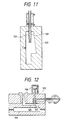
- Examined Japanese Patent Publication No. SHO. 48-41264 discloses a hollow injection-molding method and a pressurized fluid introducing and discharging apparatus therefor wherein, as shown in Fig. 11, a thin cylindrical projection 102 having a pressurized fluid passage 101 therein is disposed so that it can be projected into and retracted from a mold 103. While the projection 102 is projected into the mold 103, molten resin is injected and a pressurized fluid is introduced from the pressurized fluid passage 101, thereby forming a hollow portion. After cooling and solidification, the pressurized fluid is discharged from the hollow portion through the pressurized fluid passage 101. The projection 102 is retracted from the mold 103, and then the mold article is removed.
- Examined Japanese Patent Publication No. SHO. 59-19017 discloses a hollow injection-molding method and a pressurized fluid introducing and discharging apparatus therefor wherein, as shown in Fig. 12, a valve 107 operated by a cylinder 106 to open and close the pressurized fluid passage 101 is disposed in the intermediate portion of a molten-resin passage 105 through which injected molten resin is guided to a mold cavity 104. A pressurized fluid is introduced and discharged through the valve 107 and the pressurized fluid passage 101.
- U.S. Patent No. 4,740,150 discloses an injection-molding method and a pressurized fluid introducing and discharging apparatus therefor wherein a pressurized fluid is introduced into molten resin injected into a mold cavity, through a non-return valve and a nozzle having a pressurized fluid introducing passage which can be communicated with the mold cavity. After the resin solidifies, the nozzle is retracted to open the valve port so that the pressurized fluid in the resin is discharged to the atmosphere.
- the hollow injection-molding method and the pressurized fluid introducing and discharging apparatus therefor which are disclosed in Examined Japanese Patent Publication No. SHO. 48-41264 have problems as follows: When molten resin is injected, the molten resin flows back to the pressurized fluid passage 101 in the projection 102, thereby causing the pressurized fluid passage 101 to be clogged. In order to prevent the backflow of molten resin, it may be considered that the bore diameter of the pressurized fluid passage is reduced. However, such a manner causes to take a lot of time to discharge the pressurized fluid from the hollow portion particularly and to be the mold cycle long, thereby reducing the mold efficiency.
- the hollow injection-molding method and the pressurized fluid introducing and discharging apparatus therefor which are disclosed in Examined Japanese Patent Publication No. SHO. 59-19017 have problems as follows:
- the valve 107 When the valve 107 is opened during the introduction of the pressurized fluid, the molten resin flows back to the pressurized fluid passage 101 through the opened valve 107, thereby causing the pressurized fluid passage 101 to be clogged.
- the pressurized fluid in the introduction process may fail to be introduced into the molten resin and leak out through the molten resin and the inner surface of the mold 103 to an outside of the mold 103.
- a hollow portion can not be formed or the pressure of the pressurized fluid in a hollow portion is not maintained at a required level, thereby causing a poor moldability.
- the hollow injection-molding method and a pressurized fluid introducing and discharging apparatus therefor which are disclosed in U.S. Patent No. 4,740,150 have problems as follows:
- the apparatus has the nozzle functioning as a valve member and the valve seat, and in which the pressurized fluid introducing passage is formed in the nozzle and a pressurized fluid discharging passage is formed outside the nozzle.
- Such a construction causes the valve member and valve seat to have a complex structure, and since the pressurized fluid introducing passage is separated from the discharging passage, the structure of the pressurized fluid introducing and discharging apparatus is complicated. Furthermore, since the introducing passage is closed by the non-return valve excepting when the pressurized fluid is introduced, the mechanism of operating the non-return valve is further complicated.
- the invention is conducted in view of the above-mentioned problems, and has an object of preventing the backflow of molten resin to a pressurized fluid passage and performing sure introduction and rapid discharging of the pressurized fluid.
- a hollow injection-molding method wherein a pressurized fluid is introduced from a pressurized fluid passage 1 so as to form a hollow portion in molten resin in a mold cavity 2, and, after the molten resin in the mold cavity 2 cools and solidifies, the pressurized fluid in the hollow portion is discharged through the pressurized fluid passage 1 and the hollow injection-molded article is then removed.
- an opening portion of the pressurized fluid passage 1 in the side of a mold 3 is set to a narrowed state where the pressurized fluid can pass through the opening portion but the molten resin cannot enter the opening portion, a guide face 4 is projected into the mold 3 from the opening portion of the introducing passage in the side of the mold 3 along the opening direction, and the opening portion of the pressurized fluid passage 1 in the side of the mold 3 is widened from the narrow state to a widened state to discharge the pressurized fluid in the hollow portion.
- a pressurized fluid introducing and discharging apparatus is constructed as follows: A shaft core 6 is inserted into a sleeve 5 whose front end opens to the mold 3 with remaining a gap as the pressurized fluid passage 1 between an inner face of the sleeve 5 and the shaft core.
- the width of the opening portion of the pressurized fluid passage 1 in the side of the mold 3 can be changed by moving the shaft core 6, from the narrowed state having a width in which the pressurized fluid can pass through the opening portion but the molten resin cannot enter the opening portion, to the widened state exceeding the narrowed state or vice versa.
- the front end of the shaft core 6 projects beyond the front end face of the sleeve at least when the opening portion is in the narrowed state, and the outer peripheral face of the front end of the shaft core 6 which is projected beyond the front end face of the sleeve 5 constitutes the guide face 4 which is projected into the mold 3 from the opening portion of the pressurized fluid passage in the side of the mold 3 along the opening direction.
- Fig. 1 is a longitudinal section view showing a first embodiment of the invention.
- Fig. 2 is a diagram illustrating the narrowed state of an opening portion of a pressurized fluid passage in the side of a mold.
- Fig. 3 is a diagram illustrating the widened state of the opening portion of the pressurized fluid passage in the side of the mold.
- Fig. 4 is a diagram illustrating the operation of a guide face according to the invention.
- Fig. 5 is a longitudinal section view showing a second embodiment of the invention.
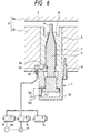
- Fig. 6 is a longitudinal section view showing a third embodiment of the invention.
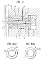
- Fig. 7 is a longitudinal section view showing a fourth embodiment of the invention.
- Fig. 8 is a diagram illustrating the narrowed and widened states in the fourth embodiment of the invention.
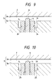
- Fig. 9 is a longitudinal section view showing a fifth embodiment of the invention.
- Fig. 10 is a longitudinal section view showing a sixth embodiment of the invention.
- Fig. 11 is a diagram illustrating the prior art.
- Fig. 12 is a diagram illustrating the prior art.
- Fig. 1 is a longitudinal section view showing a first embodiment of the pressurized fluid introducing and discharging apparatus.
- the mold 3 consists of a stationary mold 3a and a movable mold 3b, and the mold cavity 2 is formed between them.
- the pressurized fluid introducing and discharging apparatus comprises as main components the sleeve 5, the shaft core 6 and a driving device 7, and the apparatus is disposed to the mold cavity 2 in the side of the movable mold 3b.
- the pressurized fluid introducing and discharging apparatus may be disposed in the side of the stationary mold 3a.
- the pressurized fluid introducing and discharging apparatus may be disposed to not only the mold cavity 2 but also another space in the mold 3 where molten resin flows such as a sprue or a runner.
- a plurality of pressurized fluid introducing and discharging apparatuses may be disposed so as to be directed to a single space in the mold 3, or to be respectively directed to plural spaces in the mold 3.
- the sleeve 5 of the pressurized fluid introducing and discharging apparatus has a cylindrical shape, a front end of the sleeve opens to the mold 3 (in the embodiment, which is the mold cavity 2) which is a portion of introducing and discharging the presurized fluid, and the sleeve is locked to the movable mold 3b by a flange 8 formed in a rear end portion thereof.
- the cylindrical shaft core 6 is inserted into the center portion of the sleeve 5 so that an annular gap serving as the pressurized fluid passage 1 is formed between the shaft core and the inner face of the sleeve 5.
- An O-ring 9a functioning as a seal is lain between the rear end of the sleeve 5 and the shaft core 6.
- the rear end of the shaft core 6 is projected beyond the rear end of the sleeve 5 and connected to the driving device 7.
- the driving device 7 is a hydraulic device which consists of a cylinder 10 and a piston 11, and is driven by a hydraulic pressure applied from a hydraulic line 12a or 12b.
- the rear end of the shaft core 6 is connected to the piston 11. Accordingly, the shaft core 6 slides back and forth along center axis thereof in the sleeve 5 with moving the piston 11 of the driving device 7.
- a front end of a pressurized fluid supply and drain passage 13 is connected to the pressurized fluid passage 1, and the passage is formed in the movable mold 3.
- an introduction control valve 14, a recovery control valve 15, and an atmospheric release control valve 16 are connected in parallel.
- a pressurized fluid source 17 is connected to the introduction control valve 14, and a recovery vessel 18 is connected to the recovery control valve 15.
- the opening and closing of the control valves 14, 15 and 16 the supply of the pressurized fluid from the pressurized fluid source 17 to the mold 3, the recovery of the pressurized fluid from the mold 3 to the recovery vessel 18, and the discharge of the pressurized fluid in the mold 3 to the atmosphere can be respectively conducted through the pressurized fluid supply and drain passage 13 and the pressurized fluid passage 1.
- Fig. 1 shows the state where the shaft core 6 is advanced by the driving device 7.
- the front end of the shaft core 6 in this state is projected beyond the front end face of the sleeve 5 and into the mold 3 (in the embodiment, which is the mold cavity 2).
- the opening portion in the side of the mold 3 is made smaller in width than the other portions.
- the opening portion of the pressurized fluid passage 1 in the side of the mold 3 is in the narrowed state where the pressurized fluid can pass through the opening portion but the molten resin cannot enter the opening portion.
- the opening portion of the pressurized fluid passage 1 in the side of the mold 3 is widened to be in the widened state where the pressurized fluid can pass more easily as compared with the narrowed state.
- the length in the axial direction and width of the pressurized fluid passage 1 of the portion for forming the narrow state can be selected depending on the viscosity and pressure of the molten resin in the mold 3.
- the length in the axial direction is 1 to 50 mm, preferably 3 to 20 mm, and the width is 0.02 to 0.2 mm, preferably 0.05 to 0.15 mm.
- the narrowed state is set by the difference between the inner diameter of the sleeve 5 and the outer diameter of the shaft core 6, it is possible to perform the machining by a machine tool of a usual accuracy with an excellent repetitive reproducibility.
- the shaft core 6 when the shaft core 6 is advanced, its front end is projected beyond the front end face of the sleeve 5 and into the mold 3, and the outer peripheral face of the projected front end of the shaft core 6 constitutes the guide face 4 which is projected into the mold 3 from the opening portion of the pressurized fluid passage 1 in the side of the mold 3 along the opening direction.
- the guide face 4 is covered with the molten resin, the guide face 4 guides the introduced pressurized fluid so that it is surely directed into the molten resin.
- the guide face 4 for guiding the pressurized fluid will be further described with reference to Fig. 4.
- the guide face 4 When the guide face 4 is projected into the mold 3 as described above, as shown in the right side of Fig. 4, the pressurized fluid flowing out from the pressurized fluid passage 1 is guided along the guide face 4 and toward the inside of the mold 3, and thereafter the pressurized fluid further advances in the molted resin so that the pressurized fluid can be introduced into the vicinity of the center portion of the molten resin.
- the guide face 4 does not exist, as shown in the left side of Fig.
- the pressurized fluid flowing out from the pressurized fluid passage 1 is guided along the front end face of the sleeve 5 and toward the inside of the mold 3, and thereafter the pressurized fluid further advances into the molten resin. Accordingly, the pressurized fluid is liable to enter the interface of the molten resin and the inner face of the mold 103, thereby allowing easily the leakage of the pressurized fluid.
- the degree of the projection of the guide face 4 is adjusted by the interval of the shaft core 6 along the projection direction of the shaft core 6 in the space of the mold 3 wherein the shaft core 6 is projected (hereinafter, the interval is referred to as "corresponding mold space interval"). It is preferable to set the projection degree to be not less than 0.01 mm and not more than a half of the corresponding mold space interval. Generally, it is preferable to set the projection degree to be from 0.05 mm to 5 mm.
- a part being over the degree of the projected shaft may have an arbitrary shape such as a circularcone, a truncate cone and a hemisphere.
- the mold 3 is closed and a hydraulic pressure is applied through the hydraulic line 12a to the driving device 10 so as to advance the piston 11, whereby the shaft core 6 is held at the advanced position as shown in Figs. 1 and 2.
- the opening portion of the pressurized fluid passage 1 in the side of the mold 3 is set to the narrowed state, and the guide face 4 which is the outer peripheral face of the front end of the shaft core 6, is projected into the mold 3 from the opening portion of the pressurized fluid passage 1 in the side of the mold 3 along the opening direction.
- molten resin is injected into the mold 3 from an injection cylinder (not shown) of an injection molder.
- the introduction control valve 14 connected to the pressurized fluid source 17 is opened to initiate the introduction of the pressurized fluid At this time, the recovery control valve 15 and the atmospheric release control valve 16 are closed.
- the pressurized fluid is introduced, after injection of a part of molten resin required for molding, with the injection of the remaining part of the molten resin, or after completing to the injection of all parts of the molten resin.
- a fluid which has a low viscosity at room temperature and which does not react with the used resin under the temperature and pressure in the time of the injection molding.
- an inert gas such as nitrogen, a gas such as air, a liquid such as water, a resin oligomer or the like can be used.
- an inert gas such as nitrogen.
- the pressurized fluid is introduced into molten resin in the mold 3 from the pressurized fluid source 17 through the pressurized fluid supply and drain passage 13 and the pressurized fluid passage 1.
- the pressurized fluid introducing and discharging apparatus is disposed to the mold cavity 2
- the pressurized fluid is directly introduced into molten resin in the mold cavity 2 so as to form a hollow portion.
- the pressurized fluid introducing apparatus is disposed to the sprue or the runner, the pressurized fluid is introduced into molten resin being injected into the mold cavity 2 and flows together with the molten resin into the mold cavity 2 so that a hollow portion is also formed in the molten resin in the mold cavity 2.
- the introduction control valve 14 is closed, and this state is maintained for a preset period. During this period, while the molten resin in the mold cavity 2 is urged to the inner face of the mold cavity 2 by the pressure of the pressurized fluid in the hollow portion which is formed in the resin in the mold cavity 2, the molten resin in the mold cavity 2 cools down and solidifies.
- the recovery control valve 15 connected to the recovery vessel 18 is opened At the same time, a hydraulic pressure is applied through the hydraulic line 12b to the driving device 7 of the pressurized fluid introducing and discharging apparatus, and the retraction of the piston 11 causes the shaft core 6 to be retracted, whereby the opening portion of the pressurized fluid passage 1 in the side of the mold 3 is made the widened state shown in Fig. 3.
- the pressurized fluid in the hollow portion flows into the pressurized fluid passage 1 through the opening portion of the pressurized fluid passage 1 in the side of the mold 3 in which the portion is in the widened state, and the pressurized fluid is recovered into the recovery vessel 18 through the pressurized fluid supply and drain passage 13. Remains of the pressurized fluid which can not be recovered into the recovery vessel 18 is discharged into the atmosphere by closing the recovery control valve 15 after the elapse of a predetermined period and opening the atmospheric release control valve 16 for a predetermined period.
- the pressurized fluid from the hollow portion may be discharged by releasing all of the pressurized fluid into the atmosphere without recovering into the recovery vessel 18. In the view point of reusing the pressurized fluid to avoid its waste, it is preferable to recover it into the recovery vessel 18.
- the mold 3 is opened to remove the injection-molded article is removed.
- Fig. 5 shows a second embodiment of the pressurized fluid introducing and discharging apparatus of the invention.
- the embodiment is approximately the same as the above-described first embodiment, but differs from the apparatus of Fig. 1 in that an annular groove 19 is formed in the periphery of the front end of the sleeve 5.
- the annular groove 19 causes the resin to closely contact with the periphery of the front end of the sleeve 5 so as to prevent the pressurized fluid from leaking out through the interface of the sleeve 5 and the mold 3 (movable mold 3b). Therefore, the provision of the annular groove 19 can more surely prevent to occur the leakage of the pressurized fluid.
- the annular groove 19 is provided so as to prevent to be generated a gap between the resin in the annular groove 19 and sleeve 5 by shrinking the molten resin in the annular groove 19 toward sleeve 5 when the molten resin in the mold cavity cools down. Therefore, the annular groove 19 is preferably formed so as to be separated and independent from ribs and projections which are to be formed in an injection-molded article.
- Fig. 6 shows a third embodiment of the pressurized fluid introducing and discharging apparatus of the invention.
- the pressurized fluid introducing and discharging apparatus is disposed in the side of the movable mold 3b.
- the pressurized fluid introducing and discharging apparatus is also basically the same as the apparatus illustrated in conjunction with Fig. 1, however the apparatus is different in the mechanism by which the width of the opening portion of the pressurized fluid passage 1 in the side of the mold 3 is changed from the narrowed state to the widened state or vice versa, and the like.
- the same reference numerals designate the same components as those of Fig. 1.
- the annular groove 19 as described in the second embodiment is disposed on the front end face of the sleeve 5.
- the pressurized fluid supply and drain passage 13 opens from the sleeve 5 directly to outside the mold 3 without passing through the mold 3, and to which the introduction control valve 14, the recovery control valve 15, and the atmospheric release control valve 16 are connected through a connecting fitting 20 which is disposed in the outer face side of the mold 3.
- the pressurized fluid source 17 is connected to the introduction control valve 14, and the recovery vessel 18 is connected to the recovery control valve 15.
- the inner face of the front end side of the sleeve 5 is formed as a taper face which gradually increases in inner diameter in the direction from the front end to the rear end.
- the front end side of the shaft core 6 has a taper face corresponding to the taper face of the inner face of the sleeve 5.
- the shaft core 6 can slide along center axis thereof by the driving device 7. By sliding the shaft core 6 along the center axis, the width of the opening portion of the pressurized fluid passage 1 in the side of the mold 3 can be changed from the narrowed state to the widened state or vice versa.
- Fig. 6 shows the state wherein a hydraulic pressure is applied through the hydraulic line 12a to the driving device 7 and the advance of the piston 11 causes the shaft core 6 to be advanced.
- the taper faces of the sleeve 5 and that of the shaft core 6 are close to each other so that the opening portion of the pressurized fluid passage 1 in the side of the mold 3 is in the narrowed state.
- Figs. 7 and 8 show a fourth embodiment of the pressurized fluid introducing and discharging apparatus of the invention.
- the embodiment is approximately the same as the first embodiment except that the shaft core 6 is rotated about its center axis by the driving device 7, a bush 21 is disposed outside the sleeve 5, and the annular groove 19 described in the second embodiment is formed on the front end face of the bush 21.
- the identical reference numerals designate the same components as those of Fig. 1.
- the pressurized fluid introducing and discharging apparatus will be further described.
- the sleeve 5 has a cylindrical shape, opens at the front end in the mold cavity 2, and the sleeve is locked in the bush 21 inserted into the movable mold 3b by the flange 8 formed at the rear end.
- the inner diameter of the sleeve is small at the front and rear end portions, and large at the intermediate portion.
- the substantially columnar shaft core 6 is inserted into the sleeve 5.
- the shaft core 6 is fitted to the sleeve 5 to be an extent that the rotation of the shaft core 6 is not disturbed.
- a gap of the size sufficient for serving as the pressurized fluid passage 1 is formed between the sleeve 5 and the shaft core 6.
- An O-ring 9b functioning as a seal is disposed between the inner face of the rear end of the sleeve 5 having a smaller inner diameter and the shaft core 6.
- Grooves 22a and 22b are formed respectively in a part of the inner face of the front end of the sleeve 5 having the smaller inner diameter, and a part of the outer face of the front end of the shaft core 6 which is fitted into the front end of the sleeve 5.
- Each of the grooves 22a and 22b constitutes a part of the pressurized fluid passage 1, and is continuous with the pressurized fluid passage 1 which is formed between the shaft core 6 and the intermediate portion of the sleeve 5 having the large inner diameter.
- the grooves 22a and 22b are formed in parallel with the center axis of the shaft core 6.
- both the grooves 22a and 22b may be inclined in the same direction.
- the opening portion of the pressurized fluid passage 1 in the side of the mold 3 is formed by the grooves 22a and 22b so as to be arcuate as viewed from the inner face side of the mold 3.
- the grooves 22a of the sleeve 5 and the grooves 22b of the shaft core 6 are selectively positioned by the rotation of the shaft core 6 so as to be at either of the position where the grooves are displaced from each other and that where the grooves are positionally coincide with each other.
- the grooves constitute the narrowed state
- the grooves constitute the widened state.
- the inner portion of the front end of the bush 21 is cut away so that an annular groove 19 is formed between the bush and the periphery of the front end of the sleeve 5.
- the bush 21 is locked into the mold 3 (movable mold 3b) by a flange 23 which is formed at the rear end.
- groove 22a and/or 22b of the embodiment may be formed on the taper faces of the sleeve 5 and/or the shaft core 6 which are described in the third embodiment, so that the narrowed state is formed when the two taper faces closely contact with each other during the advance of the shaft core 6 and the widened state is formed by the retraction and/or rotation of the shaft core 6.
- Figs. 9 and 10 are fifth and sixth embodiments of the pressurized fluid introducing and discharging apparatus of the invention, and show modifications of the embodiment.
- the identical reference numerals designate the same components as those of Fig. 5.
- These embodiments have characteristic portion which a recess 24 or 25 is formed on the inner or outer wall of the annular groove 19.
- the recess 24 is formed on the inner wall of the annular groove 19
- the recess 25 is formed on the outer wall of the annular groove 19.
- the section shapes of the recesses 24 and 25 are not restricted to the illustrated triangular shape, and may be rectangular, semicircular, or the like.
- the resin in the annular groove 19 may perform an action in which the resin is lifted upward (as viewed in the figure) by the shrinkage during the solidification of the molten resin. Since the resin portion in the recess 24 engages with the inner wall, the lifting can be surely prevented from occurring. Also when the shrinkage causes a gap to be formed between the outer wall of the annular groove 19 and the solidifying resin, the same function is performed. Therefore, the effect that the introduced pressurized fluid becomes difficult to move in the mold cavity along the wall of the annular groove 19 is further assured.
- the recess 24 or 25 may be formed so as to surround annularly the whole of the inner or outer wall of the annular groove 19.
- the recess 24 or 25 may be formed as spots distributed on the inner or outer wall. In either case, the sealing performance can be exhibited. If the recess 24 or 25 is formed as spots, their shape may be in the shape of a circular cone, a truncated cone, a hemisphere and the like. In the illustrated examples, the recess 24 or 25 is formed on the inner or outer wall of the annular groove 19. Alternatively, a recess may be formed on the bottom face of the annular groove 19.
- the embodiments of Figs. 9 and 10 are modifications of the embodiment of Fig. 5, the configurations shown in Figs. 9 and 10 can attain the same effects even when they are applied to those of Figs. 6 and 7.
Landscapes
- Engineering & Computer Science (AREA)
- Manufacturing & Machinery (AREA)
- Mechanical Engineering (AREA)
- Moulds For Moulding Plastics Or The Like (AREA)
- Injection Moulding Of Plastics Or The Like (AREA)
- Blow-Moulding Or Thermoforming Of Plastics Or The Like (AREA)
Claims (15)
- Hohlspritzgießverfahren, bei dem ein unter Druck stehen- des Fluid aus einem Durchlaß (1) zur Einführung eines unter Druck stehenden Fluids durch einen Öffnungsbereich an der Seite einer Form (3) unter Bildung eines Hohlabschnitts im geschmolzenes Harz in einem Formhohlraum (2) eingeführt wird und, nachdem das geschmolzene Harz in dem Formhohlraum (2) sich abgekühlt und verfestigt hat, das unter Druck stehende Fluid im Hohlabschnitt durch den Durchlaß zur Einführung des unter Druck stehenden Fluids abgegeben und der hohle, spritzgegossene Formkörper anschließend entfernt wird, gekennzeichnet durch:Positionieren eines Schaftkerns (6) in dem Öffnungsabschnitt des Durchlasses (1) für ein unter Druck stehendes Fluid, so daß der Öffnungsabschnitt auf einen verengten Zustand eingestellt wird, wobei das unter Druck stehende Fluid durch den Öffnungsabschnitt treten kann, das geschmolzene Harz in dem Formhohlraum (2) jedoch nicht in den Öffnungsabschnitt eindringen kann, und Vorschieben des Schaftkerns (6) in den Formhohlraum (2) in der Richtung entlang des Einspritzens des unter Druck stehenden Fluids;Einspritzen des unter Druck stehenden Fluids durch den verengten Öffnungsabschnitt, wobei das unter Druck stehende Fluid in das geschmolzene Harz eingespritzt wird und der äußere Randbereich des vorschiebenden Schaftkerns (6) als Führungsfläche dient;Bewegen des Schaftkerns (6), um den Öffnungsabschnitt des Durchlasses (1) für ein unter Druck stehendes Fluid vom verengten Zustand in einen erweiterten Zustand zu erweitern; und Abgabe des unter Druck stehenden Fluids aus dem Hohlabschnitt durch den erweiterten Öffnungsabschnitt.
- Hohlspritzgießverfahren nach Anspruch 1, dadurch gekennzeichnet, daß der Durchlaß (1) für ein unter Druck stehendes Fluid ein Spalt ist, der zwischen dem Schaftkern (6) und einer Hülse (5) gebildet wird, wobei die Hülse (5) ein vorderes Ende hat, das sich zu einer Seite der Form (3) hin unter Bildung des Öffnungsabschnitts öffnet.
- Hohlspritzgießverfahren nach Anspruch 2, dadurch gekennzeichnet, daß der Schaftkern (6), der in die Hülse (5) eingeführt ist, entlang der zentralen Achse hin- und herbewegt wird, wobei der verengte und der erweiterte Zustand des Durchlasses (1) für das unter Druck stehende Fluid gebildet werden.
- Hohlspritzgießverfahren nach Anspruch 1, dadurch gekennzeichnet, daß eine ringförmige Rille (19) am Rand der Hülse (5) ausgebildet ist.
- Hohlspritzgießverfahren nach Anspruch 4, dadurch gekennzeichnet, daß eine Aussparung (24, 25) in mindestens einem Teil der Wand der ringförmigen Rille (19) ausgebildet ist.
- Hohlspritzgießverfahren nach Anspruch 1, dadurch gekennzeichnet, daß der Öffnungsabschnitt des Durchlasses (1) für das unter Druck stehende Fluid an der Seite der Form (3) während der Zeitspanne vom Beginn des Einspritzens des geschmolzenen Harzes in den Formhohlraum (2) bis zum Beginn der Abgabe des unter Druck stehenden Fluids in dem Hohlabschnitt auf den verengten Zustand und während der Zeitspanne vom Beginn der Abgabe des unter Druck stehenden Fluids in dem Hohlabschnitt zur Öffnung der Form (3) auf den erweiterten Zustand eingestellt wird.
- Hohlspritzgießverfahren nach Anspruch 1, dadurch gekennzeichnet, daß der Durchlaß (1) für das unter Druck stehende Fluid mit einer Quelle (17) für das unter Druck stehende Fluid, wenn das unter Druck stehende Fluid eingeführt werden soll, und mit einem Auffanggefäß (18), wenn das unter Druck stehende Fluid aus dem Hohlabschnitt abgegeben werden soll, wobei das abgegebene, unter Druck stehende Fluid aufgefangen wird, verbunden ist.
- Vorrichtung zur Einführung und Abgabe eines unter Druck stehenden Fluids, bei der ein Schaftkern (6) in eine Hülse (5) mit einem vorderen Ende, das sich in eine Form (3) öffnet, eingeführt ist, so daß ein Spalt in Bezug auf die innere Oberfläche der Hülse (5) verbleibt, wobei der Spalt als Durchlaß (1) für ein unter Druck stehendes Fluid dient, wobei die Breite des Öffnungsabschnitts des Durchlasses (1) für das unter Druck stehende Fluid an der Seite der Form (3) durch Bewegung des Schaftkerns (6) von einem verengten Zustand mit einer Breite, in der das unter Druck stehende Fluid durch den Öffnungsabschnitt treten kann, das geschmolzene Harz jedoch nicht in den Öffnungsabschnitt eindringen kann, zu einem erweiterten Zustand, der weiter als der verengte Zustand ist, oder umgekehrt verändert wird, wobei das vordere Ende des Schaftkerns (6) über die vordere Endfläche der Hülse (5) zumindest dann, wenn der Öffnungsabschnitt sich im verengten Zustand befindet, vorgeschoben ist und der äußere Rand des vorderen Endes des Schaftkerns (6), der über die vordere Endfläche der Hülse (5) vorgeschoben ist, eine Führungsfläche (4) bildet, die in die Form (3) vom Öffnungsabschnitt des Durchlasses (1) für das unter Druck stehende Fluid an der Seite der Form (3) entlang der Öffnungsrichtung vorgeschoben ist.
- Vorrichtung zur Einführung und Abgabe eines unter Druck stehenden Fluids nach Anspruch 8, dadurch gekennzeichnet, daß der Innendurchmesser der Hülse (5) am vorderen Ende der Hülse (5) klein und am rückwärtigen Ende der Hülse (5) groß ist, der Schaftkern (6) entlang der zentralen Achse gleitend geführt werden kann und der Öffnungsabschnitt des Durchlasses (1) für das unter Druck stehende Fluid an der Seite der Form (3), wenn der Schaftkern (6) vorgeschoben ist, zwischen dem Schaftkern (6) und dem vorderen Ende der Hülse (5) mit dem kleinen Innendurchmesser gebildet wird, wobei der Abschnitt sich im verengten Zustand befindet, und der Öffnungsabschnitt des Durchlasses (1) für das unter Druck stehende Fluid an der Seite der Form (3), wenn der Schaftkern (6) zurückgezogen ist, zwischen dem Schaftkern (6) und dem rückwärtigen Ende der Hülse (5) mit dem großen Innendurchmesser gebildet wird, wobei der Abschnitt sich im erweiterten Zustand befindet.
- Vorrichtung zur Einführung und Abgabe eines unter Druck stehenden Fluids nach Anspruch 8, dadurch gekennzeichnet, daß die innere Oberfläche der Hülse (5) als eine konische Oberfläche ausgebildet ist, deren Innendurchmesser allmählich in der Richtung vom vorderen Ende zum rückwärtigen Ende zunimmt und daß der Schaftkern (6) eine konische Oberfläche hat, die der konischen Oberfläche der inneren Oberfläche der Hülse (5) entspricht, und entlang der zentralen Achse gleitend geführt werden kann.
- Vorrichtung zur Einführung und Abgabe eines unter Druck stehenden Fluids nach Anspruch 8, dadurch gekennzeichnet, daß der Öffnungsabschnitt des Durchlasses (1) für das unter Druck stehende Fluid an der Seite der Form (3) durch Rillen (22a, 22b) gebildet wird, die in Abschnitten der inneren Umfangsfläche der Hülse (5) bzw. der äußeren Umfangsfläche des Schaftkerns (6) ausgebildet sind, wobei der Schaftkern (6) um die zentrale Achse rotiert werden kann und die Rillen (22a, 22b) der Hülse (5) und des Schaftkerns (6) gegeneinander versetzt sein können und sich decken können.
- Vorrichtung zur Einführung und Abgabe eines unter Druck stehenden Fluids nach Anspruch 8, dadurch gekennzeichnet, daß eine ringförmige Rille (19) in der Umfangsfläche des Öffnungsabschnitts des Durchlasses (1) für das unter Druck stehende Fluid an der Seite der Form (3) ausgebildet ist.
- Vorrichtung zur Einführung und Abgabe eines unter Druck stehenden Fluids nach Anspruch 12, dadurch gekennzeichnet, daß die Hülse (5) in der Form (3) angeordnet ist, während sie in eine Buchse (21) eingeführt ist, und daß der innere Rand der vorderen Endfläche der Buchse (21) unter Bildung einer ringförmigen Rille (19) am Rand der vorderen Endfläche der Hülse (5) weggeschnitten ist.
- Vorrichtung zur Einführung und Abgabe eines unter Druck stehenden Fluids nach Anspruch 12 oder 13, dadurch gekennzeichnet, daß eine Aussparung (24, 25) in mindestens einem Teil der Wand der ringförmigen Rille (19) ausgebildet ist.
- Vorrichtung zur Einführung und Abgabe eines unter Druck stehenden Fluids nach Anspruch 8, dadurch gekennzeichnet, daß der Durchlaß (1) für das unter Druck stehende Fluid in veränderbarer Weise mit einer Quelle (17) für das unter Druck stehende Fluid und einem Auffanggefäß (18) verbunden ist.
Applications Claiming Priority (4)
| Application Number | Priority Date | Filing Date | Title |
|---|---|---|---|
| JP357962/91 | 1991-12-27 | ||
| JP35796291 | 1991-12-27 | ||
| JP3357962A JP2884455B2 (ja) | 1991-12-27 | 1991-12-27 | 中空射出成形方法及びそれに用いる加圧流体圧入排出装置 |
| PCT/JP1992/001693 WO1993012919A1 (en) | 1991-12-27 | 1992-12-24 | Method of blow molding and pressurized fluid injection and discharge device therefor |
Publications (4)
| Publication Number | Publication Date |
|---|---|
| EP0577840A4 EP0577840A4 (de) | 1993-11-11 |
| EP0577840A1 EP0577840A1 (de) | 1994-01-12 |
| EP0577840B1 EP0577840B1 (de) | 1996-11-20 |
| EP0577840B2 true EP0577840B2 (de) | 2001-12-05 |
Family
ID=18456843
Family Applications (1)
| Application Number | Title | Priority Date | Filing Date |
|---|---|---|---|
| EP93900388A Expired - Lifetime EP0577840B2 (de) | 1991-12-27 | 1992-12-24 | Blasformverfahren, unter druck stehende flüssigkeitseinspritzvorrichtung und auswurfvorrichtung |
Country Status (7)
| Country | Link |
|---|---|
| US (1) | US5409659A (de) |
| EP (1) | EP0577840B2 (de) |
| JP (1) | JP2884455B2 (de) |
| KR (1) | KR960015292B1 (de) |
| CA (1) | CA2104457C (de) |
| DE (1) | DE69215361T3 (de) |
| WO (1) | WO1993012919A1 (de) |
Families Citing this family (16)
| Publication number | Priority date | Publication date | Assignee | Title |
|---|---|---|---|---|
| US5256047A (en) * | 1991-12-03 | 1993-10-26 | Nitrojection Corporation | Gas assisted injection molding apparatus utilizing sleeve and pin arrangement |
| US5545027A (en) * | 1993-06-02 | 1996-08-13 | Mitsubishi Gas Chemical Company, Inc. | Gas-feeding device for injection molding |
| JP3414459B2 (ja) * | 1993-11-15 | 2003-06-09 | 三菱エンジニアリングプラスチックス株式会社 | ガス注入ノズル |
| US5920943A (en) * | 1995-08-17 | 1999-07-13 | The Wooster Brush Company | Paint brush with co-injection molded handle and method of making same |
| US5989469A (en) * | 1997-09-11 | 1999-11-23 | Knight Plastics, Inc. | Method for making a non-drip valve for an inverted container |
| US6090327A (en) * | 1997-10-09 | 2000-07-18 | Churchwell; Richard | Method for molding hardenable material |
| US6042354A (en) * | 1998-02-02 | 2000-03-28 | Loren; Norman S. | Gas injection apparatus for gas assisted injection molding system |
| JPH11254457A (ja) * | 1998-03-12 | 1999-09-21 | Idemitsu Petrochem Co Ltd | 積層成形品の成形用金型および積層成形品の製造方法 |
| US6602062B1 (en) | 1999-04-23 | 2003-08-05 | Nissan Motor Co., Ltd. | Molded resin plate with internal voids and method and system for manufacturing a molded resin plate |
| US6527539B1 (en) * | 2000-10-25 | 2003-03-04 | Husky Injection Molding Systems, Ltd. | Injection unit of an injection system |
| JP4566477B2 (ja) * | 2001-08-08 | 2010-10-20 | 三菱エンジニアリングプラスチックス株式会社 | 射出成形方法 |
| US7320765B2 (en) * | 2004-04-30 | 2008-01-22 | International Automotive Components Group North America, Inc. | Gas pin for thermocouple for gas assisted injection molding |
| JP5187216B2 (ja) * | 2009-02-11 | 2013-04-24 | トヨタ紡織株式会社 | カウンタープレッシャー工法用成形型 |
| KR101402698B1 (ko) * | 2012-12-26 | 2014-06-03 | 한국생산기술연구원 | 점성유체 사출 성형장치 및 그의 제어방법 |
| KR101655987B1 (ko) * | 2014-11-21 | 2016-09-08 | (주)에뛰드 | 수축, 확장되는 다수의 언더컷성형코어를 갖는 사출금형 |
| CN108081539A (zh) * | 2016-11-21 | 2018-05-29 | 柳道万和(苏州)热流道系统有限公司 | 用于模具的气体辅助成型装置 |
Citations (1)
| Publication number | Priority date | Publication date | Assignee | Title |
|---|---|---|---|---|
| DE3936289A1 (de) † | 1989-11-01 | 1991-05-02 | Battenfeld Gmbh | Vorrichtung zum spritzgiessen von hohlraeumen enthaltenden gegenstaenden aus kunststoff |
Family Cites Families (13)
| Publication number | Priority date | Publication date | Assignee | Title |
|---|---|---|---|---|
| JPS4841264A (de) * | 1971-09-29 | 1973-06-16 | ||
| JPS5919017B2 (ja) * | 1979-05-02 | 1984-05-02 | 旭化成株式会社 | 中空物品の製造方法 |
| JPS5919017A (ja) * | 1982-07-22 | 1984-01-31 | Kawasaki Steel Corp | 鋼片移載装置 |
| GB2139548B (en) * | 1983-05-11 | 1986-11-19 | James Watson Hendry | Injection moulding |
| GB8706204D0 (en) * | 1987-03-16 | 1987-04-23 | Peerless Cinpres Ltd | Injection moulding apparatus |
| DE3834917A1 (de) * | 1988-10-13 | 1990-04-19 | Kloeckner Ferromatik Desma | Duese fuer spritzgiessmaschinen |
| DE3991547C2 (de) * | 1988-12-26 | 1994-11-03 | Asahi Chemical Ind | Verfahren und Vorrichtung zum Spritzgießen eines hohlen, geformten Gegenstandes |
| JPH03224719A (ja) * | 1990-01-31 | 1991-10-03 | Toyoda Gosei Co Ltd | 中空成形品製造用の成形型 |
| US5080570A (en) * | 1990-03-14 | 1992-01-14 | Nitrojection Corporation | Miniaturized for gas-assisted injection molding |
| JPH0712619B2 (ja) * | 1990-07-18 | 1995-02-15 | 豊田合成株式会社 | 射出中空成形型 |
| US5127814A (en) * | 1990-11-26 | 1992-07-07 | Nitrojection Corporation | Apparatus for producing a fluid-assisted injection molded product |
| US5198238A (en) * | 1991-05-16 | 1993-03-30 | Nitrojection Corporation | Apparatus having an in-the-mold gas injection pin |
| US5282730A (en) * | 1991-06-12 | 1994-02-01 | Automotive Plastic Technologies | Retractable gas injection pin for an injection mold |
-
1991
- 1991-12-27 JP JP3357962A patent/JP2884455B2/ja not_active Expired - Lifetime
-
1992
- 1992-12-24 CA CA002104457A patent/CA2104457C/en not_active Expired - Fee Related
- 1992-12-24 DE DE69215361T patent/DE69215361T3/de not_active Expired - Lifetime
- 1992-12-24 WO PCT/JP1992/001693 patent/WO1993012919A1/ja not_active Ceased
- 1992-12-24 KR KR1019930702521A patent/KR960015292B1/ko not_active Expired - Lifetime
- 1992-12-24 US US08/108,570 patent/US5409659A/en not_active Expired - Lifetime
- 1992-12-24 EP EP93900388A patent/EP0577840B2/de not_active Expired - Lifetime
Patent Citations (1)
| Publication number | Priority date | Publication date | Assignee | Title |
|---|---|---|---|---|
| DE3936289A1 (de) † | 1989-11-01 | 1991-05-02 | Battenfeld Gmbh | Vorrichtung zum spritzgiessen von hohlraeumen enthaltenden gegenstaenden aus kunststoff |
Also Published As
| Publication number | Publication date |
|---|---|
| CA2104457A1 (en) | 1993-06-28 |
| CA2104457C (en) | 1997-05-06 |
| DE69215361D1 (de) | 1997-01-02 |
| DE69215361T2 (de) | 1997-06-12 |
| EP0577840A1 (de) | 1994-01-12 |
| JPH05177667A (ja) | 1993-07-20 |
| WO1993012919A1 (en) | 1993-07-08 |
| EP0577840B1 (de) | 1996-11-20 |
| KR960015292B1 (ko) | 1996-11-07 |
| JP2884455B2 (ja) | 1999-04-19 |
| US5409659A (en) | 1995-04-25 |
| EP0577840A4 (de) | 1993-11-11 |
| DE69215361T3 (de) | 2002-08-22 |
Similar Documents
| Publication | Publication Date | Title |
|---|---|---|
| EP0577840B2 (de) | Blasformverfahren, unter druck stehende flüssigkeitseinspritzvorrichtung und auswurfvorrichtung | |
| US5798080A (en) | Method of producing a hollow resin body and apparatus therefor | |
| US5198238A (en) | Apparatus having an in-the-mold gas injection pin | |
| JPH04219219A (ja) | 射出中空成形型 | |
| USRE35705E (en) | Gas assisted injection molding apparatus utilizing sleeve and pin arrangement | |
| US6214275B1 (en) | Injection nozzle and method for injection molding | |
| US4830812A (en) | Method and system for making a hollow-shaped body from molten resin by injection molding | |
| KR950009716B1 (ko) | 사출 성형 노즐장치 | |
| US20060159798A1 (en) | Method for producing mould parts by injection and plugged needle nozzle for an injection mould | |
| US7314368B2 (en) | Dual-cylinder injection molding apparatus | |
| US6375449B1 (en) | Gas injection pin mechanism for plastic injection molding systems | |
| JP3233769B2 (ja) | 射出成形機のシャットオフノズル | |
| US6062842A (en) | Mold for use in a gas-assisted injection molding system and runner shut-off subsystem for use therein | |
| JP3342032B2 (ja) | 中空射出成形用加圧流体圧入装置 | |
| JP2776244B2 (ja) | 加圧流体圧入排出装置 | |
| JPH0976275A (ja) | 流体注入・回収装置 | |
| JP3186287B2 (ja) | ディスク用射出成形金型装置 | |
| EP1274553B1 (de) | Spritzgiessmaschine mit zwei zylindern | |
| JP3318959B2 (ja) | 射出成形用射出ノッズル | |
| JPH07299835A (ja) | 加圧流体圧入排出装置 | |
| WO2002036323A9 (en) | Co-injection valve-gate bushing with separate material flow paths | |
| JPH07308941A (ja) | 加圧流体圧入排出装置 | |
| JPH05124062A (ja) | ガス吹込射出成形用射出ノズル | |
| JPH05177668A (ja) | 中空射出成形用加圧流体圧入装置 | |
| JPH0367623A (ja) | 射出成形用ノズル装置 |
Legal Events
| Date | Code | Title | Description |
|---|---|---|---|
| PUAI | Public reference made under article 153(3) epc to a published international application that has entered the european phase |
Free format text: ORIGINAL CODE: 0009012 |
|
| 17P | Request for examination filed |
Effective date: 19930820 |
|
| AK | Designated contracting states |
Kind code of ref document: A1 Designated state(s): CH DE FR GB IT LI NL |
|
| 17Q | First examination report despatched |
Effective date: 19950203 |
|
| GRAG | Despatch of communication of intention to grant |
Free format text: ORIGINAL CODE: EPIDOS AGRA |
|
| GRAH | Despatch of communication of intention to grant a patent |
Free format text: ORIGINAL CODE: EPIDOS IGRA |
|
| GRAH | Despatch of communication of intention to grant a patent |
Free format text: ORIGINAL CODE: EPIDOS IGRA |
|
| GRAA | (expected) grant |
Free format text: ORIGINAL CODE: 0009210 |
|
| AK | Designated contracting states |
Kind code of ref document: B1 Designated state(s): CH DE FR GB IT LI NL |
|
| PG25 | Lapsed in a contracting state [announced via postgrant information from national office to epo] |
Ref country code: FR Free format text: LAPSE BECAUSE OF NON-PAYMENT OF DUE FEES Effective date: 19961120 |
|
| REG | Reference to a national code |
Ref country code: CH Ref legal event code: NV Representative=s name: BOVARD AG PATENTANWAELTE |
|
| REF | Corresponds to: |
Ref document number: 69215361 Country of ref document: DE Date of ref document: 19970102 |
|
| ET | Fr: translation filed | ||
| ITF | It: translation for a ep patent filed | ||
| PLBI | Opposition filed |
Free format text: ORIGINAL CODE: 0009260 |
|
| PLBQ | Unpublished change to opponent data |
Free format text: ORIGINAL CODE: EPIDOS OPPO |
|
| 26 | Opposition filed |
Opponent name: BATTENFELD GMBH Effective date: 19970502 |
|
| NLR1 | Nl: opposition has been filed with the epo |
Opponent name: BATTENFELD GMBH |
|
| PLBF | Reply of patent proprietor to notice(s) of opposition |
Free format text: ORIGINAL CODE: EPIDOS OBSO |
|
| PGFP | Annual fee paid to national office [announced via postgrant information from national office to epo] |
Ref country code: FR Payment date: 19971209 Year of fee payment: 6 |
|
| PGFP | Annual fee paid to national office [announced via postgrant information from national office to epo] |
Ref country code: NL Payment date: 19971223 Year of fee payment: 6 |
|
| PGFP | Annual fee paid to national office [announced via postgrant information from national office to epo] |
Ref country code: CH Payment date: 19980109 Year of fee payment: 6 |
|
| PLBF | Reply of patent proprietor to notice(s) of opposition |
Free format text: ORIGINAL CODE: EPIDOS OBSO |
|
| PLBF | Reply of patent proprietor to notice(s) of opposition |
Free format text: ORIGINAL CODE: EPIDOS OBSO |
|
| PG25 | Lapsed in a contracting state [announced via postgrant information from national office to epo] |
Ref country code: LI Free format text: LAPSE BECAUSE OF NON-PAYMENT OF DUE FEES Effective date: 19981231 Ref country code: CH Free format text: LAPSE BECAUSE OF NON-PAYMENT OF DUE FEES Effective date: 19981231 |
|
| PLBQ | Unpublished change to opponent data |
Free format text: ORIGINAL CODE: EPIDOS OPPO |
|
| PLAB | Opposition data, opponent's data or that of the opponent's representative modified |
Free format text: ORIGINAL CODE: 0009299OPPO |
|
| R26 | Opposition filed (corrected) |
Opponent name: BATTENFELD GMBH Z. H. HERRN NORBERT BIELICH Effective date: 19970502 |
|
| NLR1 | Nl: opposition has been filed with the epo |
Opponent name: BATTENFELD GMBH Z. H. HERRN NORBERT BIELICH |
|
| PG25 | Lapsed in a contracting state [announced via postgrant information from national office to epo] |
Ref country code: NL Free format text: LAPSE BECAUSE OF NON-PAYMENT OF DUE FEES Effective date: 19990701 |
|
| REG | Reference to a national code |
Ref country code: CH Ref legal event code: PL |
|
| NLV4 | Nl: lapsed or anulled due to non-payment of the annual fee |
Effective date: 19990701 |
|
| REG | Reference to a national code |
Ref country code: FR Ref legal event code: ST |
|
| PLAW | Interlocutory decision in opposition |
Free format text: ORIGINAL CODE: EPIDOS IDOP |
|
| PLAW | Interlocutory decision in opposition |
Free format text: ORIGINAL CODE: EPIDOS IDOP |
|
| PUAH | Patent maintained in amended form |
Free format text: ORIGINAL CODE: 0009272 |
|
| STAA | Information on the status of an ep patent application or granted ep patent |
Free format text: STATUS: PATENT MAINTAINED AS AMENDED |
|
| 27A | Patent maintained in amended form |
Effective date: 20011205 |
|
| AK | Designated contracting states |
Kind code of ref document: B2 Designated state(s): CH DE FR GB IT LI NL |
|
| REG | Reference to a national code |
Ref country code: GB Ref legal event code: IF02 |
|
| EN | Fr: translation not filed | ||
| PG25 | Lapsed in a contracting state [announced via postgrant information from national office to epo] |
Ref country code: IT Free format text: LAPSE BECAUSE OF NON-PAYMENT OF DUE FEES Effective date: 20051224 |
|
| PGFP | Annual fee paid to national office [announced via postgrant information from national office to epo] |
Ref country code: GB Payment date: 20101222 Year of fee payment: 19 |
|
| PGFP | Annual fee paid to national office [announced via postgrant information from national office to epo] |
Ref country code: DE Payment date: 20111221 Year of fee payment: 20 |
|
| REG | Reference to a national code |
Ref country code: DE Ref legal event code: R071 Ref document number: 69215361 Country of ref document: DE |
|
| REG | Reference to a national code |
Ref country code: GB Ref legal event code: PE20 Expiry date: 20121223 |
|
| PG25 | Lapsed in a contracting state [announced via postgrant information from national office to epo] |
Ref country code: GB Free format text: LAPSE BECAUSE OF EXPIRATION OF PROTECTION Effective date: 20121223 |