EP0578528B1 - Elément électrophotographique photosensible - Google Patents
Elément électrophotographique photosensible Download PDFInfo
- Publication number
- EP0578528B1 EP0578528B1 EP93401626A EP93401626A EP0578528B1 EP 0578528 B1 EP0578528 B1 EP 0578528B1 EP 93401626 A EP93401626 A EP 93401626A EP 93401626 A EP93401626 A EP 93401626A EP 0578528 B1 EP0578528 B1 EP 0578528B1
- Authority
- EP
- European Patent Office
- Prior art keywords
- charge
- layer
- photosensitive member
- electrophotographic photosensitive
- image
- Prior art date
- Legal status (The legal status is an assumption and is not a legal conclusion. Google has not performed a legal analysis and makes no representation as to the accuracy of the status listed.)
- Expired - Lifetime
Links
Images
Classifications
-
- G—PHYSICS
- G03—PHOTOGRAPHY; CINEMATOGRAPHY; ANALOGOUS TECHNIQUES USING WAVES OTHER THAN OPTICAL WAVES; ELECTROGRAPHY; HOLOGRAPHY
- G03G—ELECTROGRAPHY; ELECTROPHOTOGRAPHY; MAGNETOGRAPHY
- G03G5/00—Recording-members for original recording by exposure, e.g. to light, to heat or to electrons; Manufacture thereof; Selection of materials therefor
- G03G5/02—Charge-receiving layers
- G03G5/04—Photoconductive layers; Charge-generation layers or charge-transporting layers; Additives therefor; Binders therefor
- G03G5/06—Photoconductive layers; Charge-generation layers or charge-transporting layers; Additives therefor; Binders therefor characterised by the photoconductive material being organic
- G03G5/0622—Heterocyclic compounds
- G03G5/0624—Heterocyclic compounds containing one hetero ring
- G03G5/0635—Heterocyclic compounds containing one hetero ring being six-membered
- G03G5/0638—Heterocyclic compounds containing one hetero ring being six-membered containing two hetero atoms
-
- G—PHYSICS
- G03—PHOTOGRAPHY; CINEMATOGRAPHY; ANALOGOUS TECHNIQUES USING WAVES OTHER THAN OPTICAL WAVES; ELECTROGRAPHY; HOLOGRAPHY
- G03G—ELECTROGRAPHY; ELECTROPHOTOGRAPHY; MAGNETOGRAPHY
- G03G5/00—Recording-members for original recording by exposure, e.g. to light, to heat or to electrons; Manufacture thereof; Selection of materials therefor
- G03G5/02—Charge-receiving layers
- G03G5/04—Photoconductive layers; Charge-generation layers or charge-transporting layers; Additives therefor; Binders therefor
- G03G5/05—Organic bonding materials; Methods for coating a substrate with a photoconductive layer; Inert supplements for use in photoconductive layers
- G03G5/0503—Inert supplements
- G03G5/051—Organic non-macromolecular compounds
- G03G5/0521—Organic non-macromolecular compounds comprising one or more heterocyclic groups
-
- G—PHYSICS
- G03—PHOTOGRAPHY; CINEMATOGRAPHY; ANALOGOUS TECHNIQUES USING WAVES OTHER THAN OPTICAL WAVES; ELECTROGRAPHY; HOLOGRAPHY
- G03G—ELECTROGRAPHY; ELECTROPHOTOGRAPHY; MAGNETOGRAPHY
- G03G5/00—Recording-members for original recording by exposure, e.g. to light, to heat or to electrons; Manufacture thereof; Selection of materials therefor
- G03G5/14—Inert intermediate or cover layers for charge-receiving layers
- G03G5/147—Cover layers
- G03G5/14708—Cover layers comprising organic material
Definitions
- the present invention relates to an electrophotographic photosensitive member, and an electrophotographic apparatus employing the electrophotographic photosensitive member.
- Organic photosensitive members employing organic photoconductive material have come to be widely used as an electrophotographic photosensitive member in recent years.
- Conventional organic photosensitive members because of the disadvantages of low sensitivity and low durability thereof, are useful only for low-speed electrophotographic apparatuses. The above disadvantages are being overcome with development of novel materials.
- Organic photosensitive members however, have still disadvantages of deterioration of the properties on exposure to ozone or NO x . Since ozone and NO x are formed in an electrophotographic apparatus, a conventional photosensitive member, when used in an electrophotographic apparatus, are liable to cause deterioration of charge retention ability, decrease of sensitivity, smearing of images, and lowering of other performances.
- an antioxidant of a hindered phenol type, a phosphine type, or a sulfur type is added into the photosensitive layer to trap ozone and NO x .
- the addition of the antioxidant tends to cause other disadvantages such as drop of initial sensitivity and rise of residual potential although the resistance to ozone and NO x is improved.
- the antioxidant which has trapped ozone or nitrogen oxides impedes carrier generation or carrier transportation in the photosensitive layer, thereby causing decrease of sensitivity and chargeability disadvantageously.
- FR-A-1 308 762 is related to an electrophotographic member comprising a photosensitive layer deposited on a support, this layer containing a pyrazine compound.
- this document does not describe an electrophotographic photosensitive member in which its photosensitive layer has a laminated structure.
- Patent Abstracts of Japan of JP-A-2 072 370 discloses an electrophotographic photosensitive member in which a pyrazine derivative is contained as a charge-transporting material in its charge transporting layer.
- the present invention intends to provide a novel electrophotographic photosensitive member which is not deteriorated by ozone and nitrogen oxides and is satisfactory in durability.
- the electrophotographic photosensitive member of the present invention has a photosensitive layer with a laminated structure in which a charge-generating layer and a charge transporting layer are laminated on a support, the charge-generating layer contains 10-100% by weight of a charge-generating material, the charge-transporting layer contains 20-80% by weight of a charge-transporting material and a pyrazine derivative, and the pyrazine derivative content is 0.01-30%. by weight based on the photosensitive layer.
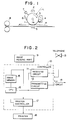
- Fig. 1 is a side view of an example of the electrophotographic apparatus employing the electrophotographic photosensitive member of the present invention.
- Fig. 2 is a block diagram of an example of a facsimile system employing the electrophotographic apparatus of the present invention.
- the electrophotographic photosensitive member of the present invention comprises a pyrazine derivative represented by the general formula (1) in a photosensitive layer on a support, or in a protection layer formed, when necessary, on the photosensitive layer: where R 1 , R 2 , R 3 , and R 4 are each independently a hydrogen atom, a hydroxyl group, a halogen atom, or an organic group.
- the organic group includes the groups of amino, carboxyl, aldehyde, carbonyl, alkoxy, amide, ester, mercapto, alkyl, allyl, aryl, heterocyclic, etc.
- At least one of R 1 , R 2 , R 3 , and R 4 is an alkyl group, an allyl group, an aromatic ring group, or a heterocyclic group.
- the alkyl group and the allyl group include preferably those having 1 to 6 carbon atoms.
- the aromatic group includes phenyl, naphthyl, anthryl, pyrenyl, naphthacenyl, perylenyl, fluorenyl, phenanthryl, etc..
- the heterocyclic group includes preferably pyridyl, thienyl, furyl, quinolyl, pyrrolyl, piperidyl, indolyl, pyrimidyl, imidazolyl, etc.
- pyrazine derivatives are 2,3,5, 6-tetramethylpyrazine, 2,3-dimethylpyrazine, 2,3-diethylpyrazine, 2,3-bis(2-pyridyl)pyrazine, 2,2'-bipyrazine, 4,4'-bipyrazine, 2,3,5-trimethylpyrazine, 2,6-dimethylpyrazine, 2-ethylpyrazine, 2-vinylpyrazine, 2-methyl-3-ethoxypyrazine, 2-methyl-3-isopropoxypyrazine, 2-methyl-3-methoxypyrazine, 5-methylpyrazine-2-carboxylic acid, pyrazine acid, 2-(aminomethyl)-5-methylpyrazine, 2-methylmercapto-3-methylpyrazine, etc.
- the photosensitive layer of the electrophotographic photosensitive member in the present invention is of a lamination structure constituted of at least a charge-generating layer and a charge-transporting layer.
- the photosensitive layer of a lamination structure has a charge-generating layer containing a charge-generating substance and a charge-transporting layer containing a charge-transporting substance formed in the named order on a support, or formed in the reversed order.
- the pyrazine derivative of Formula (1) is incorporated into the charge-transporting layer, or in both of the charge-transporting layer and charge-generating layer.
- the pyrazine derivative of Formula (1) is contained in an amount of from 0.01 to 30 % by weight, more preferably 0.5 to 20 % by weight, still more preferably from 0.5 to 10 % by weight, based on the weight of the photosensitive layer.
- the charge-generating substance includes phthalocyanine pigments, polycyclic quinone pigments, azo pigments, perylene pigments, indigo pigments, quinacridone pigments, azulenium salt pigments, squarilium dyes, cyanine dyes, pyrylium dyes, thiopyrylium dyes, xanthene coloring matters, quinoneimine coloring matters, triphenylmethane coloring matters, styryl coloring matters, selenium, tellurium, amorphous silicon, cadmium sulfide, etc.
- the charge-transporting substance includes pyrene compounds, N-alkylcarbazole compounds, hydrazone compounds, N,N-dialkylaniline compounds, diphenylamine compounds, triphenylamine compounds, triphenylmethane compounds, pyrazoline compounds, styryl compounds, stilbene compounds, polynitro compounds, polycyano compounds, etc., and polymers having the above compound immobilized thereon as a pendant, and so forth.
- the charge-generating layer preferably has a thickness of from 0.001 to 6 ⁇ m, more preferably from 0.01 to 2 ⁇ m, and the charge-transporting layer preferably has a thickness of from 10 to 35 ⁇ m, more preferably from 15 to 30 ⁇ m.
- the charge-generating layer contains the charge-generating substance in an amount of from 10 to 100 %, more preferably from 50 to 100 % by weight.
- the charge-transporting layer contains the charge-transporting substance in an amount of from 20 to 80 %, more preferably from 30 to 70 % by weight.
- the electrophotographic photosensitive member of the present invention can be prepared by vacuum deposition of substances for the photosensitive layer, or by film formation from a combination of the substances and a suitable binder.
- the binder includes polyesters, polyurethanes, polyarylates, polyethylene, polystyrene, polybutadienes, polycarbonates, polyamides, polypropylenes, polyimides, polyamide-imides, polysulfones, polyaryl ethers, polyacetals, nylons, phenol resins, acrylic resins, silicone resins, epoxy resins, allyl resins, alkyd resins, butyral resins, etc., and copolymers thereof.
- a protecting film may be provided on the photosensitive layer of the electrophotographic photosensitive member of the present invention.
- the protecting layer is constructed mainly of a resin.
- the material constructing the protecting layer includes polyesters, polyurethanes, polyarylates, polyethylene, polystyrene, polybutadienes, polycarbonates, polyamides, polypropylenes, polyimides, polyamide-imides, polysulfones, polyaryl ethers, polyacetals, nylons, phenol resins, acrylic resins, silicone resins, epoxy resins, urea resins, allyl resins, alkyd resins, butyral resins, etc.
- the protecting layer preferably has a thickness of from 0.05 to 15 ⁇ m, more preferably from 1 to 10 ⁇ m.
- the protecting layer may contain the pyrazine derivative of Formula (1) in a preferred amount of from 0 to 40 % by weight based on the weight of the protecting layer.
- the protecting layer may contain a charge-transporting charge-transporting substance for retaining the properties of the protecting layer, electroconductive inorganic particles for controlling the electric resistance of the protecting layer, fluorine-containing fine particles for lowering the friction resistance of the surface of the protecting layer, etc.
- the charge-transporting substance for the protecting layer includes those mentioned above.
- the electroconductive particles include particles of SnO 2 , ITO, etc.
- the fluorine-containing fine resin particles include particles of polytetrafluoroethylene, polychlorotrifluoroethylene, polyvinylidene fluoride, polydichlorodifluoroethylene, tetrafluoroethylene-perfluoroalkyl vinyl ether copolymers, tetrafluoroethylene-hexafluoropropylene copolymers, tetrafluoroethylene-ethylene copolymers, tetrafluoroethylene-hexafluoropropylene-perfluoroalkyl vinyl ether copolymers, and combinations of two or more of them.
- the support may be made of an electroconductive material such as metals and alloys of iron, copper, nickel, aluminum, titanium, tin, antimony, indium, lead, zinc, gold, and silver, etc., and oxides thereof, carbon, and electroconductive resins.
- the support is preferably in a shape of a cylinder, a belt, or a sheet.
- the support may be produced by molding the above electroconductive material into a desired shape, or may be prepared by applying as a coating material or vapor-depositing the above electroconductive material on another supporting member.
- a subbing layer may be provided between the support and the photosensitive layer.
- the subbing layer serves to control charge injection at the interface or as an adhesive layer.
- the subbing layer is mainly composed of a binder resin which may contain an electroconductive material or a surfactant.
- the binder resin for constructing the subbing layer includes polyesters, polyurethanes, polyarylates, polyethylene, polystyrene, polybutadienes, polycarbonates, polyamides, polypropylenes, polyimides, polyamide-imides, polysulfones, polyaryl ethers, polyacetals, nylons, phenol resins, acrylic resins, silicone resins, epoxy resins, urea resins, allyl resins, alkyd resins, butyral resins, etc.
- the subbing layer preferably has a thickness of from 0.05 to 7 ⁇ m, more preferably from 0.1 to 2 ⁇ m.
- the photosensitive layer or the protecting layer may be formed by coating application by bar coater coating, knife coater coating, roll coater coating, spray coating, dip coating, electrostatic coating, powder coating, or the like.
- the photosensitive layer may be formed by vapor deposition.
- Fig. 1 illustrates schematically an example of the constitution of a transfer type electrophotographic apparatus employing an electrophotographic photosensitive member of the present invention.
- a drum-shaped electrophotographic photosensitive member 1 of the present invention is driven to rotate around the axis 1a in the arrow direction at a prescribed peripheral speed.
- the photosensitive member 1 is uniformly charged positively or negatively at the peripheral face during the rotation by an electrostatic charging means 2, and then exposed to image-exposure light L (e.g., slit exposure, laser beam-scanning exposure, etc.) at the exposure portion 3 with an image-exposure means (not shown in the drawing), whereby an electrostatic latent image is successively formed on the peripheral surface in accordance with the image exposure.
- image-exposure light L e.g., slit exposure, laser beam-scanning exposure, etc.
- the formed electrostatic latent image is developed with a toner by a developing means 4.
- the developed toner image is successively transferred by a transfer means 5 onto a surface of a recording medium P which is fed between the photosensitive member 1 and the transfer means 5 synchronously with the rotation of the photosensitive member 1 from a feeder not shown in the drawing.
- the recording medium P which has received the transferred image is separated from the photosensitive member surface, and introduced to an image fixing means 8 for fixation of the image and sent out from the copying machine as a duplicate copy.
- the surface of the photosensitive member 1, after the image transfer, is cleaned with a cleaning means 6 to remove any remaining un-transferred toner, and is treated for charge elimination with a pre-exposure means 7 for repeated use for image formation.
- the generally employed charging means 2 for uniformly charging the photosensitive member 1 is a corona charging apparatus.
- the generally employed transfer means 5 is also a corona charging means.
- two or more of the constitutional elements of the above-described photosensitive member 1, the developing means 4, the cleaning means 6, etc. may be integrated into one device unit, which may be made demountable from the main body of the apparatus.
- the cleaning means 6 is combined with the photosensitive member 1 into one device unit which is demountable from the main body of the apparatus by aid of a guiding means such as a rail in the main body of the apparatus.
- the device unit may have a charging means and/or a developing means.
- the optical image exposure light L may be projected onto the photosensitive member as reflected light or transmitted light from an original copy, or otherwise the information read out by a sensor from an original may be signalized, and light is projected, onto a photosensitive member, by scanning with a laser beam, driving a light-emitting diode array, or driving a liquid crystal shutter array according to the signal.
- the optical image exposure light L is employed for printing the received data.
- Fig. 2 is a block diagram of an example of a facsimile system employing the electrophotographic photosensitive member as the printer.
- a controller 10 controls the image-reading part 9 and a printer 18. The entire of the controller 10 is controlled by a CPU 16. Readout data from the image reading part 9 is transmitted through a transmitting circuit 12 to the other communication station. Data received from the other communication station is transmitted through a receiving circuit 11 to a printer 18. The image data is stored in an image memory 15. A printer controller 17 controls a printer 18. The numeral 13 denotes a telephone set.
- the images are recorded in such a manner that the CPU 16 reads out one page of the image information, and sends out the one page of the signalized information to the printer controller 17, which controls the printer 18 on receiving the one page of the information from CPU 16 to record the image information.
- the CPU 16 receives the subsequent page of information.
- a coating liquid for a charge-generating layer was prepared by dispersing 10 parts of tris azo pigment represented by the formula below, 5 parts of polycarbonate (bisphenol A type, number-average molecular weight (Mn): 20,000), and 600 parts of cyclohexanone by means of a sand mill: where Ar is: and X is -Cl.
- This coating liquid was applied on the aforementioned subbing layer, and was dried at 120°C for 20 minutes to form a charge-generating layer of 0.15 ⁇ m thick.
- styryl compound represented by the formula below 50 parts of polycarbonate (bisphenol Z type, Mn: 25,000), and 0.1 parts of the pyrazine derivative represented by the formula below: were dispersed in 800 parts of chlorobenzene by means of a ball mill to prepare a coating liquid for the charge-transporting layer.
- This coating liquid was applied on the aforementioned charge-generating layer by dip coating, and was dried at 130°C for 90 minutes to form a charge-transporting layer of 18 ⁇ m thick, thus completing an electrophotographic photosensitive member of the present invention.
- electrophotographic photosensitive members were prepared in the same manner as described above, except that the amount of the pyrazine derivative was changed to 0.25 part, 0.5 part, 1.0 part, 2.0 parts, 4.0 parts, or 8.0 parts as shown in Table 1.
- the electrophotographic photosensitive member thus prepared was mounted on an electrophotographic apparatus (made by Canon K.K., trade name: CLC-500). With this apparatus, continuous copying of 10,000 sheets was conducted. The results are shown in Table 1. Amount of pyrazine (parts by weight) 0.1 0.25 0.5 1.0 2.0 4.0 8.0 Image quality ⁇ ⁇ 0 0 0 0 0 ⁇ : Undesired image of stripes appearing slightly across the recording paper sheet, but no problem practically 0 : Clear image obtained
- An aluminum sheet of 250 mm long, 150 mm wide, and 0.5 mm thick was used as an electroconductive support.
- a subbing layer, a charge-generating layer, and a charge-transporting layer which were the same as those in Example 1 were formed by bar coater coating to prepare seven kinds of electrophotographic photosensitive members of the present invention.
- the obtained seven kinds of electrophotographic photosensitive members were tested for the sensitivity and the residual potential at a temperature of 25°C and a humidity of 50 % by means of a paper analyzer (trade name EPA-8100, made by Kawaguchi Denki K.K.). The results are shown in Table 2.
- Amount of pyrazine (parts by weight) 0.1 0.25 0.5 1.0 2.0 4.0 8.0 Sensitivity ( ⁇ J/cm 2 ) 0.50 0.51 0.50 0.53 0.52 0.55 0.60
- the sensitivity in the present invention means a quantity of light energy per unit area required to reduce the charged potential to a 1/2 value of the initial charged potential when light is projected onto a charged electrophotographic photosensitive member.
- the initial charged potential was -600 V
- the wavelength of the light was 790 nm.
- the residual potential in the present invention means a charged potential 0.5 second after the completion of eliminating, with a halogen lamp, charge of the electrophotographic photosensitive member having been charged at -600 V.
- Table 3 shows the changes of the respective potentials after the charging step, the image-exposure step, and the charge elimination step caused by the durability test.
- the charged potentials after completion of the steps of charging, image-exposure, and charge elimination are measured, respectively, and further, after the durability test, the electrophotographic photosensitive member is treated through the same steps, and the corresponding potentials are measured.
- the changes of the potentials are shown in Table 3.
- the dark part potential change ⁇ Vd means the change of the potential after the charging step
- the light part potential change ⁇ V1 means the change of the potential after completion of image exposure step
- the residual potential change ⁇ Vr means the change of the potential after completion of the destaticizing step.
- the electrophotographic photosensitive member thus prepared was mounted on an electrophotographic apparatus (made by Canon K.K., trade name: CLC-500). With this apparatus, continuous copying of 10,000 sheets was conducted. The results are shown in Table 7. Amount of pyrazine (parts by weight) 0.3 0.5 1.0 2.0 5.0 8.0 Image quality ⁇ 0 0 0 0 0 ⁇ : Undesired image of stripes appearing slightly across the recording paper sheet, but no problem practically 0 : Clear image obtained
- An aluminum sheet of 250 mm long, 150 mm wide, and 0.5 mm thick was used as an electroconductive support.
- a subbing layer, a charge-generating layer, and a charge-transporting layer were formed in the same manner as in Example 5 by bar coater coating to prepare 6 kinds of electrophotographic photosensitive members of the present invention.
- An electrophotographic photosensitive member was prepared in the same manner as in Example 5 except that no pyrazine derivative was used.
- the electrophotographic photosensitive member thus prepared was mounted on an electrophotographic apparatus (made by Canon K.K., trade name: CLC-500). With this apparatus, continuous copying of 10,000 sheets was conducted. As the result, undesired black image in stripes appeared across the recording paper sheet.
- the electrophotographic photosensitive member thus prepared was mounted on an electrophotographic apparatus (made by Canon K.K., trade name: CLC-500). With this apparatus, continuous copying of 10,000 sheets was conducted. The results are shown in Table 10. Amount of pyrazine (parts by weight) 0.3 0.7 1.5 2.5 4.0 5.5 Image quality ⁇ 0 0 0 0 0 ⁇ : Undesired image of stripes appearing slightly across the recording paper sheet, but no problem practically 0 : Clear image obtained
- An aluminum sheet of 250 mm long, 150 mm wide, and 0.5 mm thick was used as an electroconductive support.
- a subbing layer, a charge-generating layer, and a charge-transporting layer were formed in the same manner as in Example 7 by bar coater coating to prepare six kinds of electrophotographic photosensitive members of the present invention.
- An electrophotographic photosensitive member was prepared in the same manner as in Example 7 except that no pyrazine derivative was used.
- the electrophotographic photosensitive member thus prepared was mounted on an electrophotographic apparatus (made by Canon K.K., trade name: CLC-500). With this apparatus, continuous copying of 10,000 sheets was conducted. As the result, undesired black image in stripes appeared across the recording paper sheet.
Landscapes
- Physics & Mathematics (AREA)
- General Physics & Mathematics (AREA)
- Spectroscopy & Molecular Physics (AREA)
- Photoreceptors In Electrophotography (AREA)
Claims (2)
- Elément photosensible électrophotographique, comprenant une couche photosensible à structure stratifiée dans laquelle une couche de production de charge et une couche de support de charge sont stratifiées sur un support,la couche de production de charge contenant 10 à 100 % en poids d'une matière de production de charge,la couche de transport de charge contenant 20 à 80 % en poids d'une matière de transport de charge et un dérivé de pyrazine représenté par la formule générale :dans laquelle R1, R2, R3 et R4 représentent chacun indépendamment un atome d'hydrogène, un groupe hydroxyle, un atome d'halogène ou un groupe organique ; et au moins un des groupes R1, R2, R3 et R4 représentent un groupe alkyle, un groupe allyle, un groupe à noyau aromatique ou un groupe hétérocyclique,

etla teneur en dérivé de pyrazine est comprise dans l'intervalle de 0,01 à 30 % en poids sur la base de la couche photosensible. - Elément photosensible électrophotographique suivant la revendication 1, dans lequel la couche de production de charge et la couche de transport de charge contiennent l'une et l'autre le dérivé de pyrazine.
Applications Claiming Priority (4)
| Application Number | Priority Date | Filing Date | Title |
|---|---|---|---|
| JP16773392 | 1992-06-25 | ||
| JP167733/92 | 1992-06-25 | ||
| JP173261/92 | 1992-06-30 | ||
| JP17326192 | 1992-06-30 |
Publications (3)
| Publication Number | Publication Date |
|---|---|
| EP0578528A2 EP0578528A2 (fr) | 1994-01-12 |
| EP0578528A3 EP0578528A3 (fr) | 1994-10-12 |
| EP0578528B1 true EP0578528B1 (fr) | 1999-04-14 |
Family
ID=26491675
Family Applications (1)
| Application Number | Title | Priority Date | Filing Date |
|---|---|---|---|
| EP93401626A Expired - Lifetime EP0578528B1 (fr) | 1992-06-25 | 1993-06-24 | Elément électrophotographique photosensible |
Country Status (3)
| Country | Link |
|---|---|
| US (1) | US5393628A (fr) |
| EP (1) | EP0578528B1 (fr) |
| DE (1) | DE69324411T2 (fr) |
Families Citing this family (12)
| Publication number | Priority date | Publication date | Assignee | Title |
|---|---|---|---|---|
| DE69525996T2 (de) * | 1994-06-22 | 2002-09-19 | Canon K.K., Tokio/Tokyo | Elektrophotographisches Gerät |
| KR20010073144A (ko) * | 1998-09-11 | 2001-07-31 | 윌리엄 데이비드 바우어, 캐씨 로버타 샘스 | 제2 표면에 결합된 잉크-함유 표면을 특징으로 하는 다층적층체 제조용 접착제 |
| US6221545B1 (en) | 1999-09-09 | 2001-04-24 | Imation Corp. | Adhesives for preparing a multilayer laminate featuring an ink-bearing surface bonded to a second surface |
| US7189989B2 (en) * | 2002-08-22 | 2007-03-13 | Fuji Photo Film Co., Ltd. | Light emitting element |
| US8084170B2 (en) * | 2007-03-13 | 2011-12-27 | Ricoh Company, Ltd. | Electrophotographic photoconductor, electrophotographic process cartridge containing the same and electrophotographic apparatus containing the same |
| US7923185B2 (en) * | 2008-04-30 | 2011-04-12 | Xerox Corporation | Pyrazine containing charge transport layer photoconductors |
| US8962133B2 (en) | 2011-12-12 | 2015-02-24 | Canon Kabushiki Kaisha | Electrophotographic member, intermediate transfer member, image forming apparatus, and method for manufacturing electrophotographic member |
| CN109074008B (zh) * | 2016-04-25 | 2021-10-29 | 京瓷办公信息系统株式会社 | 电子照相感光体、处理盒及图像形成装置 |
| JP6463534B1 (ja) | 2017-09-11 | 2019-02-06 | キヤノン株式会社 | 現像剤担持体、プロセスカートリッジおよび電子写真装置 |
| JP7187266B2 (ja) | 2018-10-25 | 2022-12-12 | キヤノン株式会社 | 電子写真感光体、プロセスカートリッジ及び電子写真装置 |
| JP2020067635A (ja) | 2018-10-26 | 2020-04-30 | キヤノン株式会社 | 電子写真感光体、プロセスカートリッジおよび電子写真装置 |
| JP7293049B2 (ja) | 2019-08-26 | 2023-06-19 | キヤノン株式会社 | 現像部材、電子写真プロセスカートリッジおよび電子写真画像形成装置 |
Family Cites Families (9)
| Publication number | Priority date | Publication date | Assignee | Title |
|---|---|---|---|---|
| FR1308762A (fr) * | 1960-10-04 | 1962-11-09 | Gevaert Photo Prod Nv | Matériel électrophotographique |
| BE595696A (fr) * | 1960-10-04 | |||
| US4119460A (en) * | 1977-05-25 | 1978-10-10 | Eastman Kodak Company | π-Deficient N-heteroaromatic chemical sensitizers for heterogeneous organic photoconductor compositions and methods |
| JPH0272370A (ja) * | 1988-09-07 | 1990-03-12 | Konica Corp | 電子写真感光体 |
| JP2637499B2 (ja) * | 1988-09-08 | 1997-08-06 | キヤノン株式会社 | 電子写真感光体 |
| JP2761007B2 (ja) * | 1988-11-21 | 1998-06-04 | 三田工業株式会社 | 電子写真感光体 |
| JPH02176665A (ja) * | 1988-12-28 | 1990-07-09 | Canon Inc | 電子写真感光体 |
| JP2538393B2 (ja) * | 1990-05-24 | 1996-09-25 | キヤノン株式会社 | 電子写真感光体、該電子写真感光体を備えた電子写真装置並びファクシミリ |
| JP2782109B2 (ja) * | 1990-07-30 | 1998-07-30 | キヤノン株式会社 | 電子写真感光体、該電子写真感光体を備えた電子写真装置並びにファクシミリ |
-
1993
- 1993-06-23 US US08/079,824 patent/US5393628A/en not_active Expired - Fee Related
- 1993-06-24 DE DE69324411T patent/DE69324411T2/de not_active Expired - Fee Related
- 1993-06-24 EP EP93401626A patent/EP0578528B1/fr not_active Expired - Lifetime
Also Published As
| Publication number | Publication date |
|---|---|
| US5393628A (en) | 1995-02-28 |
| DE69324411D1 (de) | 1999-05-20 |
| EP0578528A2 (fr) | 1994-01-12 |
| DE69324411T2 (de) | 1999-09-16 |
| EP0578528A3 (fr) | 1994-10-12 |
Similar Documents
| Publication | Publication Date | Title |
|---|---|---|
| US4555463A (en) | Photoresponsive imaging members with chloroindium phthalocyanine compositions | |
| EP0466094B1 (fr) | Elément électrophotographique photosensible | |
| EP1850185A2 (fr) | Élément d'imagerie | |
| EP1465019B1 (fr) | Elément de formation d'images | |
| US5393628A (en) | Electrophotographic photosensitive member, and electrophotographic apparatus employing the same | |
| US5403686A (en) | Electrophotographic element and imaging method exhibiting reduced incidence of laser interference patterns | |
| US5504558A (en) | Electrophotographic photosensitive member, and electrophotographic apparatus and device unit employing the same | |
| US7291432B2 (en) | Imaging members | |
| US7514191B2 (en) | Imaging member | |
| JPH11258835A (ja) | 電子写真用画像形成部材及びその製造方法 | |
| US8043784B2 (en) | Imaging member and methods of forming the same | |
| JP3352166B2 (ja) | 電子写真感光体、それを有する電子写真装置および装置ユニット | |
| EP0670526A2 (fr) | Appareil électrophotographique, cassette de traitement et matériau photosensible | |
| JPH0675396A (ja) | 電子写真感光体及びこの電子写真感光体を用いた電子写真装置 | |
| JPH05204175A (ja) | 電子写真用感光体 | |
| JPH0264553A (ja) | 電子写真感光体 | |
| JPH10207085A (ja) | 電子写真感光体 | |
| US6946225B2 (en) | Electrophotographic element protected from photofatigue induced by visible light | |
| JPH10254151A (ja) | 電荷減少に耐性の電子写真画像形成部材 | |
| JP3684043B2 (ja) | 電子写真感光体、該電子写真感光体を有するプロセスカ−トリッジ及び電子写真装置 | |
| JP2929549B2 (ja) | 電子写真感光体 | |
| JPH05107789A (ja) | 画像形成方法 | |
| JP2879372B2 (ja) | 電子写真感光体、該電子写真感光体を備えた電子写真装置並びにファクシミリ | |
| JPH07128895A (ja) | 電子写真用感光体及び電子写真装置 | |
| JP2920689B2 (ja) | 電子写真感光体、該電子写真感光体を備えた電子写真装置並びにファクシミリ |
Legal Events
| Date | Code | Title | Description |
|---|---|---|---|
| PUAI | Public reference made under article 153(3) epc to a published international application that has entered the european phase |
Free format text: ORIGINAL CODE: 0009012 |
|
| AK | Designated contracting states |
Kind code of ref document: A2 Designated state(s): DE FR GB |
|
| PUAL | Search report despatched |
Free format text: ORIGINAL CODE: 0009013 |
|
| AK | Designated contracting states |
Kind code of ref document: A3 Designated state(s): DE FR GB |
|
| 17P | Request for examination filed |
Effective date: 19950303 |
|
| 17Q | First examination report despatched |
Effective date: 19961028 |
|
| GRAG | Despatch of communication of intention to grant |
Free format text: ORIGINAL CODE: EPIDOS AGRA |
|
| GRAG | Despatch of communication of intention to grant |
Free format text: ORIGINAL CODE: EPIDOS AGRA |
|
| GRAG | Despatch of communication of intention to grant |
Free format text: ORIGINAL CODE: EPIDOS AGRA |
|
| GRAH | Despatch of communication of intention to grant a patent |
Free format text: ORIGINAL CODE: EPIDOS IGRA |
|
| GRAH | Despatch of communication of intention to grant a patent |
Free format text: ORIGINAL CODE: EPIDOS IGRA |
|
| GRAA | (expected) grant |
Free format text: ORIGINAL CODE: 0009210 |
|
| AK | Designated contracting states |
Kind code of ref document: B1 Designated state(s): DE FR GB |
|
| ET | Fr: translation filed | ||
| REF | Corresponds to: |
Ref document number: 69324411 Country of ref document: DE Date of ref document: 19990520 |
|
| PLBE | No opposition filed within time limit |
Free format text: ORIGINAL CODE: 0009261 |
|
| STAA | Information on the status of an ep patent application or granted ep patent |
Free format text: STATUS: NO OPPOSITION FILED WITHIN TIME LIMIT |
|
| 26N | No opposition filed | ||
| REG | Reference to a national code |
Ref country code: GB Ref legal event code: IF02 |
|
| PGFP | Annual fee paid to national office [announced via postgrant information from national office to epo] |
Ref country code: FR Payment date: 20050608 Year of fee payment: 13 |
|
| PGFP | Annual fee paid to national office [announced via postgrant information from national office to epo] |
Ref country code: DE Payment date: 20050616 Year of fee payment: 13 |
|
| PGFP | Annual fee paid to national office [announced via postgrant information from national office to epo] |
Ref country code: GB Payment date: 20050622 Year of fee payment: 13 |
|
| PG25 | Lapsed in a contracting state [announced via postgrant information from national office to epo] |
Ref country code: GB Free format text: LAPSE BECAUSE OF NON-PAYMENT OF DUE FEES Effective date: 20060624 |
|
| PG25 | Lapsed in a contracting state [announced via postgrant information from national office to epo] |
Ref country code: DE Free format text: LAPSE BECAUSE OF NON-PAYMENT OF DUE FEES Effective date: 20070103 |
|
| GBPC | Gb: european patent ceased through non-payment of renewal fee |
Effective date: 20060624 |
|
| REG | Reference to a national code |
Ref country code: FR Ref legal event code: ST Effective date: 20070228 |
|
| PG25 | Lapsed in a contracting state [announced via postgrant information from national office to epo] |
Ref country code: FR Free format text: LAPSE BECAUSE OF NON-PAYMENT OF DUE FEES Effective date: 20060630 |