EP0579176A2 - Imprimante et machine de traitement de feuilles xérographique - Google Patents
Imprimante et machine de traitement de feuilles xérographique Download PDFInfo
- Publication number
- EP0579176A2 EP0579176A2 EP93111212A EP93111212A EP0579176A2 EP 0579176 A2 EP0579176 A2 EP 0579176A2 EP 93111212 A EP93111212 A EP 93111212A EP 93111212 A EP93111212 A EP 93111212A EP 0579176 A2 EP0579176 A2 EP 0579176A2
- Authority
- EP
- European Patent Office
- Prior art keywords
- sheet
- sheet transport
- roller
- image
- transport
- Prior art date
- Legal status (The legal status is an assumption and is not a legal conclusion. Google has not performed a legal analysis and makes no representation as to the accuracy of the status listed.)
- Withdrawn
Links
- 238000012545 processing Methods 0.000 title claims abstract description 43
- 239000000463 material Substances 0.000 claims abstract description 6
- 238000010438 heat treatment Methods 0.000 claims description 75
- 230000007723 transport mechanism Effects 0.000 claims description 49
- 238000003384 imaging method Methods 0.000 claims description 41
- 238000003825 pressing Methods 0.000 claims description 29
- 238000007599 discharging Methods 0.000 claims description 18
- 230000007246 mechanism Effects 0.000 claims description 16
- 238000012546 transfer Methods 0.000 claims description 9
- 238000009434 installation Methods 0.000 claims description 8
- 229920005989 resin Polymers 0.000 claims description 8
- 239000011347 resin Substances 0.000 claims description 8
- 230000002093 peripheral effect Effects 0.000 claims description 5
- 230000003287 optical effect Effects 0.000 claims 2
- 210000000078 claw Anatomy 0.000 description 36
- 230000036961 partial effect Effects 0.000 description 13
- 238000004140 cleaning Methods 0.000 description 6
- XLYOFNOQVPJJNP-UHFFFAOYSA-N water Substances O XLYOFNOQVPJJNP-UHFFFAOYSA-N 0.000 description 6
- 230000005494 condensation Effects 0.000 description 5
- 238000009833 condensation Methods 0.000 description 5
- 238000005192 partition Methods 0.000 description 5
- 230000002829 reductive effect Effects 0.000 description 5
- 239000004020 conductor Substances 0.000 description 4
- 229920003051 synthetic elastomer Polymers 0.000 description 3
- 239000005061 synthetic rubber Substances 0.000 description 3
- XEEYBQQBJWHFJM-UHFFFAOYSA-N Iron Chemical compound [Fe] XEEYBQQBJWHFJM-UHFFFAOYSA-N 0.000 description 2
- 230000002411 adverse Effects 0.000 description 2
- 230000015572 biosynthetic process Effects 0.000 description 2
- 230000006698 induction Effects 0.000 description 2
- 238000012423 maintenance Methods 0.000 description 2
- 229920006324 polyoxymethylene Polymers 0.000 description 2
- 230000000717 retained effect Effects 0.000 description 2
- 125000006850 spacer group Chemical group 0.000 description 2
- PXGOKWXKJXAPGV-UHFFFAOYSA-N Fluorine Chemical compound FF PXGOKWXKJXAPGV-UHFFFAOYSA-N 0.000 description 1
- 229930182556 Polyacetal Natural products 0.000 description 1
- 239000004642 Polyimide Substances 0.000 description 1
- 230000001154 acute effect Effects 0.000 description 1
- 239000000853 adhesive Substances 0.000 description 1
- 230000000694 effects Effects 0.000 description 1
- 230000005611 electricity Effects 0.000 description 1
- 238000001704 evaporation Methods 0.000 description 1
- 238000002474 experimental method Methods 0.000 description 1
- 239000011737 fluorine Substances 0.000 description 1
- 229910052731 fluorine Inorganic materials 0.000 description 1
- NBVXSUQYWXRMNV-UHFFFAOYSA-N fluoromethane Chemical compound FC NBVXSUQYWXRMNV-UHFFFAOYSA-N 0.000 description 1
- 229920006015 heat resistant resin Polymers 0.000 description 1
- 239000012212 insulator Substances 0.000 description 1
- 229910052742 iron Inorganic materials 0.000 description 1
- 230000000670 limiting effect Effects 0.000 description 1
- 230000007774 longterm Effects 0.000 description 1
- 230000007257 malfunction Effects 0.000 description 1
- 238000004519 manufacturing process Methods 0.000 description 1
- 239000000155 melt Substances 0.000 description 1
- 238000000034 method Methods 0.000 description 1
- 238000012986 modification Methods 0.000 description 1
- 230000004048 modification Effects 0.000 description 1
- 229920001721 polyimide Polymers 0.000 description 1
- 239000000843 powder Substances 0.000 description 1
- 238000000926 separation method Methods 0.000 description 1
- 238000003860 storage Methods 0.000 description 1
- 238000011144 upstream manufacturing Methods 0.000 description 1
Images









Classifications
-
- G—PHYSICS
- G03—PHOTOGRAPHY; CINEMATOGRAPHY; ANALOGOUS TECHNIQUES USING WAVES OTHER THAN OPTICAL WAVES; ELECTROGRAPHY; HOLOGRAPHY
- G03G—ELECTROGRAPHY; ELECTROPHOTOGRAPHY; MAGNETOGRAPHY
- G03G15/00—Apparatus for electrographic processes using a charge pattern
- G03G15/65—Apparatus which relate to the handling of copy material
- G03G15/6552—Means for discharging uncollated sheet copy material, e.g. discharging rollers, exit trays
-
- G—PHYSICS
- G03—PHOTOGRAPHY; CINEMATOGRAPHY; ANALOGOUS TECHNIQUES USING WAVES OTHER THAN OPTICAL WAVES; ELECTROGRAPHY; HOLOGRAPHY
- G03G—ELECTROGRAPHY; ELECTROPHOTOGRAPHY; MAGNETOGRAPHY
- G03G15/00—Apparatus for electrographic processes using a charge pattern
- G03G15/20—Apparatus for electrographic processes using a charge pattern for fixing, e.g. by using heat
- G03G15/2003—Apparatus for electrographic processes using a charge pattern for fixing, e.g. by using heat using heat
- G03G15/2014—Apparatus for electrographic processes using a charge pattern for fixing, e.g. by using heat using heat using contact heat
- G03G15/2017—Structural details of the fixing unit in general, e.g. cooling means, heat shielding means
- G03G15/2028—Structural details of the fixing unit in general, e.g. cooling means, heat shielding means with means for handling the copy material in the fixing nip, e.g. introduction guides, stripping means
-
- G—PHYSICS
- G03—PHOTOGRAPHY; CINEMATOGRAPHY; ANALOGOUS TECHNIQUES USING WAVES OTHER THAN OPTICAL WAVES; ELECTROGRAPHY; HOLOGRAPHY
- G03G—ELECTROGRAPHY; ELECTROPHOTOGRAPHY; MAGNETOGRAPHY
- G03G15/00—Apparatus for electrographic processes using a charge pattern
- G03G15/20—Apparatus for electrographic processes using a charge pattern for fixing, e.g. by using heat
- G03G15/2003—Apparatus for electrographic processes using a charge pattern for fixing, e.g. by using heat using heat
- G03G15/2014—Apparatus for electrographic processes using a charge pattern for fixing, e.g. by using heat using heat using contact heat
- G03G15/2039—Apparatus for electrographic processes using a charge pattern for fixing, e.g. by using heat using heat using contact heat with means for controlling the fixing temperature
-
- G—PHYSICS
- G03—PHOTOGRAPHY; CINEMATOGRAPHY; ANALOGOUS TECHNIQUES USING WAVES OTHER THAN OPTICAL WAVES; ELECTROGRAPHY; HOLOGRAPHY
- G03G—ELECTROGRAPHY; ELECTROPHOTOGRAPHY; MAGNETOGRAPHY
- G03G15/00—Apparatus for electrographic processes using a charge pattern
- G03G15/20—Apparatus for electrographic processes using a charge pattern for fixing, e.g. by using heat
- G03G15/2003—Apparatus for electrographic processes using a charge pattern for fixing, e.g. by using heat using heat
- G03G15/2014—Apparatus for electrographic processes using a charge pattern for fixing, e.g. by using heat using heat using contact heat
- G03G15/2064—Apparatus for electrographic processes using a charge pattern for fixing, e.g. by using heat using heat using contact heat combined with pressure
-
- G—PHYSICS
- G03—PHOTOGRAPHY; CINEMATOGRAPHY; ANALOGOUS TECHNIQUES USING WAVES OTHER THAN OPTICAL WAVES; ELECTROGRAPHY; HOLOGRAPHY
- G03G—ELECTROGRAPHY; ELECTROPHOTOGRAPHY; MAGNETOGRAPHY
- G03G15/00—Apparatus for electrographic processes using a charge pattern
- G03G15/65—Apparatus which relate to the handling of copy material
- G03G15/6555—Handling of sheet copy material taking place in a specific part of the copy material feeding path
- G03G15/657—Feeding path after the transfer point and up to the fixing point, e.g. guides and feeding means for handling copy material carrying an unfused toner image
-
- G—PHYSICS
- G03—PHOTOGRAPHY; CINEMATOGRAPHY; ANALOGOUS TECHNIQUES USING WAVES OTHER THAN OPTICAL WAVES; ELECTROGRAPHY; HOLOGRAPHY
- G03G—ELECTROGRAPHY; ELECTROPHOTOGRAPHY; MAGNETOGRAPHY
- G03G21/00—Arrangements not provided for by groups G03G13/00 - G03G19/00, e.g. cleaning, elimination of residual charge
- G03G21/16—Mechanical means for facilitating the maintenance of the apparatus, e.g. modular arrangements
- G03G21/1661—Mechanical means for facilitating the maintenance of the apparatus, e.g. modular arrangements means for handling parts of the apparatus in the apparatus
- G03G21/1685—Mechanical means for facilitating the maintenance of the apparatus, e.g. modular arrangements means for handling parts of the apparatus in the apparatus for the fixing unit
-
- G—PHYSICS
- G03—PHOTOGRAPHY; CINEMATOGRAPHY; ANALOGOUS TECHNIQUES USING WAVES OTHER THAN OPTICAL WAVES; ELECTROGRAPHY; HOLOGRAPHY
- G03G—ELECTROGRAPHY; ELECTROPHOTOGRAPHY; MAGNETOGRAPHY
- G03G2215/00—Apparatus for electrophotographic processes
- G03G2215/00362—Apparatus for electrophotographic processes relating to the copy medium handling
- G03G2215/00367—The feeding path segment where particular handling of the copy medium occurs, segments being adjacent and non-overlapping. Each segment is identified by the most downstream point in the segment, so that for instance the segment labelled "Fixing device" is referring to the path between the "Transfer device" and the "Fixing device"
- G03G2215/00413—Fixing device
-
- G—PHYSICS
- G03—PHOTOGRAPHY; CINEMATOGRAPHY; ANALOGOUS TECHNIQUES USING WAVES OTHER THAN OPTICAL WAVES; ELECTROGRAPHY; HOLOGRAPHY
- G03G—ELECTROGRAPHY; ELECTROPHOTOGRAPHY; MAGNETOGRAPHY
- G03G2215/00—Apparatus for electrophotographic processes
- G03G2215/00362—Apparatus for electrophotographic processes relating to the copy medium handling
- G03G2215/00367—The feeding path segment where particular handling of the copy medium occurs, segments being adjacent and non-overlapping. Each segment is identified by the most downstream point in the segment, so that for instance the segment labelled "Fixing device" is referring to the path between the "Transfer device" and the "Fixing device"
- G03G2215/00417—Post-fixing device
- G03G2215/00421—Discharging tray, e.g. devices stabilising the quality of the copy medium, postfixing-treatment, inverting, sorting
-
- G—PHYSICS
- G03—PHOTOGRAPHY; CINEMATOGRAPHY; ANALOGOUS TECHNIQUES USING WAVES OTHER THAN OPTICAL WAVES; ELECTROGRAPHY; HOLOGRAPHY
- G03G—ELECTROGRAPHY; ELECTROPHOTOGRAPHY; MAGNETOGRAPHY
- G03G2215/00—Apparatus for electrophotographic processes
- G03G2215/00362—Apparatus for electrophotographic processes relating to the copy medium handling
- G03G2215/00535—Stable handling of copy medium
- G03G2215/00649—Electrodes close to the copy feeding path
-
- G—PHYSICS
- G03—PHOTOGRAPHY; CINEMATOGRAPHY; ANALOGOUS TECHNIQUES USING WAVES OTHER THAN OPTICAL WAVES; ELECTROGRAPHY; HOLOGRAPHY
- G03G—ELECTROGRAPHY; ELECTROPHOTOGRAPHY; MAGNETOGRAPHY
- G03G2215/00—Apparatus for electrophotographic processes
- G03G2215/00362—Apparatus for electrophotographic processes relating to the copy medium handling
- G03G2215/00535—Stable handling of copy medium
- G03G2215/00679—Conveying means details, e.g. roller
Definitions
- the present invention relates to xerographic printing and sheet processing apparatus, and more specifically, it relates to such apparatus included in image forming equipment for a copying machine or facsimile equipment, or the like.
- Fig. 1 schematically illustrating in perspective view a facsimile terminal comprising image forming equipment in accordance with an embodiment of the present invention.
- Fig. 2 a vertical section providing a schematic view through the facsimile terminal.
- the image forming equipment is shown chiefly to comprise a reading part 1 for reading image information of an original document put into an upper portion of the equipment, xerographic printing and sheet processing apparatus 2 disposed in the center of the equipment, receiving the image information and printing it onto a sheet, and a sheet feeding part 3 disposed at the bottom of the equipment, for feeding copying sheets to the xerographic printing and sheet processing apparatus 2.
- the reading part 1 includes an original retainer 5 on which the original is put, an original-transport section 6 for transporting the original, and an original-discharge tray 7 for storing originals discharged from the original-transport part 6.
- a sensor 8 for reading image information of the original is disposed in the original-transport section 6.
- An operation panel 9 comprising various keys and a display is disposed on the upper surface of the equipment.
- a hand set 10 is disposed along an upper portion of the equipment.
- the xerographic printing and sheet processing apparatus 2 includes an imaging unit 11 comprising a photoconductive drum and associated elements, a developing unit 14 comprising a developing roller 12 and a toner cartridge 13, containing magnetic, single component toner, a laser unit 15 for forming on the surface of the photoconductive drum of the imaging unit 11 a latent image according to the information received, and an image fixing and sheet transport unit 16 for fixing an image printed from developing toner onto the sheet surface by the imaging unit 11.
- a sheet discharge tray 17 is provided on the left of the image fixing and sheet transporting unit 16 in the figure.
- the feeding part 3 includes a feed cassette 21 which is detachably mounted in an opening 20 provided in the bottom portion of the equipment body, and a sheet-feeding unit 22 for feeding sheets from the feeding cassette 21 and supplying them to the xerographic printing and sheet processing apparatus 2.
- the equipment body consists of an upper case 25 and a lower case 26.
- the upper case 25 is openable on a hinge 27.
- the upper case 25 contains the reading part 1 and the imaging unit 11, as well as the developing unit 14 and the laser unit 15 of the xerographic printing and sheet processing apparatus 2.
- the lower case 26 holds the image fixing and sheet transporting unit 16 of the xerographic printing and sheet processing apparatus 2, and the feeding part 3.
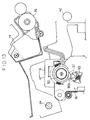
- FIG. 3 the imaging unit 11 and the image fixing and sheet transporting unit 16 of the xerographic printing and sheet processing apparatus 2 are depicted in detail in an enlarged partial view.
- the imaging unit 11 is housed within a housing 30. Upwardly protruding mounting flanges 31 are formed at the upper ends of sides of the housing 30. A vertically extending slot 31a is formed in each mounting flange 31 and the slot 31a holds a pin 32 provided in a body frame of the facsimile equipment. Thus, the imaging unit 11 is vertically movable within a predetermined range. Furthermore, downward projecting retainers 33 are formed at lower portions of the housing 30. The retainers 33 receive pins 34 likewise provided in the body frame, positioning the imaging unit 30 in the vertical direction. A photoconductive drum 35 is rotatably mounted in the end of the imaging unit 11 adjacent the developing unit 14.
- a cleaning blade 36 for removing toner residual on the surface of the photoconductive drum 35 is provided alongside the photoconductive drum 35.
- the residual toner removed from the surface of the photoconductive drum 35 by the cleaning blade 36 is collects into a residual toner container 37 defined by the housing 30.
- a transfer roller 40 printing the toner-developed image on the photoconductive drum 35 by transferring it onto the sheet, is disposed under the photoconductive drum 35.
- the transfer roller 40 is rotatably supported by the frame of the lower case 26.
- a main charger 41 for charging the surface of the photoconductive drum 35 is disposed above it.
- an image printing apparatus for printing a toner-developed image onto the surface of a sheet consists of the imaging unit 11, the developing unit 14, the transfer roller 40 and the main charger 41.
- the photoconductive drum 35 is negatively charged and the toner carries positive electric charge, the sheet is accordingly charged by the transfer roller 40 to have negative polarity.
- a sheet transport guide 45 for guiding the sheet bearing the printed toner image toward the image fixing and sheet transporting unit 16 is disposed downstream from the image printing apparatus in a sheet-discharging direction of the image forming equipment.
- the sheet transport guide 45 is formed of a resin providing controlled conductivity.
- a resin having superficial resistivity ranging from 1 ⁇ 1010 ⁇ to 1 ⁇ 1014 ⁇ is used.
- Toray Industries' "TOYOLACPAREL TP10" (superficial resistivity: 1 ⁇ 1011 ⁇ ), or Japan Synthetic Rubber, Ltd.'s "ABS EM12” (superficial resistivity: 2 ⁇ 1011 ⁇ ) can preferably be used.
- a middle frame 46 is disposed immediate the imaging unit 11.
- the middle frame 46 is formed of, for example, iron plate, wherein it is an electric conductor.
- the middle frame 46 is in contact with the imaging unit 11 through the flanges 46b and is grounded through another frame.
- Two cutouts 46a are formed in the middle frame corresponding to opposite sides widthwise of the printing sheet.
- the image fixing and sheet transporting unit 16 includes a heating roller 50, inside which is a heater 50a, against which a sheet transport pressure roller 51 is pressible.
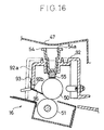
- a fixing unit upper housing 52 surroundingly covers the heating roller 50.
- the upper housing 52 extends axially along the heating roller 50 and is detachably mounted on a lower housing (not shown).
- the lower housing is fixed to frames 53 of a pair which is provided flanking the axial ends of the rollers 50 and 51.
- a channel 52a through which a mounting member 54 is detachably inserted is formed in the central portion of the upper wall of the upper housing 52 along the axial direction of the rollers.
- the mounting member 54 has a central cavity 54a.
- a cleaning element 55 for cleaning the surface of the heating roller 50 is mounted in the bottom of the mounting member 54.
- Two cutouts 52c are formed in lateral wall 52b of the upper housing 52 on the sheet-discharging side along the axial direction of the rollers.
- a support pin 56 is located in each cutout 52c.
- a separating claw 57 for separating a sheet in transport from the heating roller 50 is rotatably supported on each support pin 56.
- Each separating claw 57 comprises a support portion 57a supported on the corresponding support pin 56, a separator portion 57b extending from the support portion 57a toward the heating roller 50 and a lever portion 57c extending from the support portion 57a to the exterior side of the lateral wall 52b.
- the separator portion 57b is pressed against the surface of the heating roller 50 by a torsion spring 58.
- the lever portion 57c protrudes from the cutout 52c and is thus exposed to the exterior side of the lateral wall 52b.
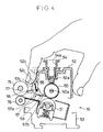
- an operator pushes a lever portion 57c toward the side wall 52b as shown in Fig. 4, in order that the end of the separator portions 57b be lifted off the surface of the heating roller 50.
- the separating claw 57 By means of the separating claw 57, a sheet which in undergoing image fixing tends to wind around the surface of the heating roller 50 is readily detached therefrom. Furthermore, when the upper housing 52 is mounted or dismounted, for example for parts replacement, the end of the separating claw 57 is securely separable from the surface of the heating roller 50 by holding the lever portion 57c, whereby potential damage therein to the heating roller surface 50 is prevented.
- the heating roller 50 is rotatably supported on the frame 53 by a bearing 60. Additionally, a rod 61 of the pressure roller 51 is supported on the frame 53 through a bearing 62 and a spring 63. A knob 62a projecting upward is provided on the upper portion of the bearing 62.
- the bearing 62 is vertically shiftable and is constantly impelled against the heating roller 50 by the elasticity of the spring 63.
- the bearings 60 and 61, and the spring 63 are disposed at either end of the roller.
- a pressure releasing lever 65 is rotatably mounted, concentric with the heating roller 50.
- Each of the pair of pressure releasing levers 65 includes a retaining ring 65a peripherally encircling the bearing 60, a cam 65b formed in a portion of the retaining ring 65a, from which an L-shaped lever arm 65c extends toward the image forming unit.
- One end of the pressure releasing lever 65 is impelled counter-clockwise in Fig. 3 by a spring 66 retained by the frame 53.
- two cutouts 70a and 70b are formed in the lateral wall 52b of the upper housing on the side toward the image printing unit and a fuse catch 71 is formed between the cutouts 70a and 70b.
- a temperature fuse 72 is laced through along the interior side of the housing 52 and both ends of the temperature fuse 72 are fixed to the exterior surface of the housing lateral wall 52d by screws.
- the heater 50a inside the heating roller 50 is electrically wired to the fuse 72 ends fixed by the screws.
- Guides 52e and 71a are formed at the lower ends of the lateral wall 52d and the catch 71, respectively, whereby a supplied printing sheet is guided as it is introduced between the heating roller 50 and pressure roller 51.
- the middle frame 46 extends out over the image fixing and sheet transporting unit 16 and serves as a partition 47 between the image fixing and sheet transporting unit 16 and the image forming equipment upper portion.
- the partition 47 includes dihedral surfaces 47a and 47b meeting in a lowest collecting surface 47c above the mounting member 54, wherein waterdrops forming along the dihedral surfaces 47a and 47b collect.
- a pair of sheet discharge rollers 75 and 76 is disposed downstream of the image fixing and sheet transporting unit 16.
- the upper roller 75 is fixed to a drive shaft 77 supported on the frame 53.
- the lower roller 76 is rotatably supported in the lower housing (not shown).
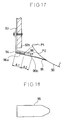
- the lower roller 76 is formed of a resin such as POM (polyacetal) and has a plurality of axially-cut peripheral grooves 76a fluted to be U-shaped sectionally, as shown in Figs. 7 and 8.
- the lower roller 76 is substantially cylindrical being, for example, 12 mm in outside diameter, 4.3 mm inside diameter and 8 mm in thickness; and each groove 76a is 1.2 mm in width, there being fifteen circumferentially equidistant grooves.
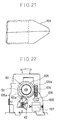
- the groove is cut such that an angle ⁇ , between the side of the groove and a line tangent to the cylindrical surface of the lower roller 76 is determined to be 90° or less. Therefore, when the lower roller 76 is rotated in the direction indicated by arrow A in Fig. 8 to discharge the sheet, the trailing edge of the sheet will drop into the groove. Thus, the sheet is surely discharged toward the discharge tray 17.
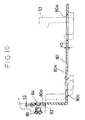
- the image fixing and sheet transporting unit 16 is mounted onto the equipment body by installing the frames 53 disposed at both ends of the unit onto a mount frame 80, shown in Fig. 10.
- a mount frame 80 At the bottom end of each frame 53 are first and second hooks 81 and 82; and on the downstream, discharging-side thereof is a flange 83.
- the mount frame 80 includes a horizontal portion 80e into which the frame 53 is placed, and a vertical portion 80d.
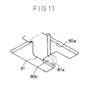
- the first hook 81 of the frame 53 includes a projection 81a projecting toward the image printing unit and its upper corner is curved.
- the first hook 81 is inserted into a cutout 80a formed in the mount frame 80. Referring to Fig.
- a latch portion 80b protruding into the cutout 80a is formed in the mount frame 80, wherein the projection 81a of the first hook 81 can abut on the latch portion 80b.
- the second hook 82 includes a projection 82a projecting toward the first hook 81.
- the upper surface 82b of the projection 82a inclines downward.
- a cutout 80c is formed in the mount frame 80 corresponding to the second hook 82.
- the cutout 80c is formed large enough that the second hook 82 can be entirely inserted into it at once.
- the vertical portion 80d is bent upward from an end of the horizontal portion 80e.
- a threaded hole 84 is formed in the vertical portion 80d, wherein the flange 83 of the frame 53 is mounted by a screw 85.
- a small gap t3 e.g., 0.1 to 0.5 mm
- both hooks 81 and 82 of each frame 53 are inserted into the cutouts 80a and 80c of the mount frame 80. Then, the frame 53 is moved rightward in Fig. 10, wherein the projection 82a of the second hook 82 is guided downward as its inclined surface 82b rides on the edge of the cutout 80c. The projection 81a of the first hook 81 goes under the latch portion 80b.
- the image fixing and sheet transporting unit 16 can be temporarily set in the vertical direction merely by shifting the frame 53 laterally.
- the unit 16 is temporarily set, the gap t3 is left between the vertical portion 80d of the mount frame 80 and the flange 83 of the frame 53. In this state, if the screw 85 is screwed down tight into the threaded hole 84, the flange 83 is deflected and adhered immediate the vertical portion 80d. Thus, the fixing and transporting unit 16 is stably fixed to the mount frame 80 by the elastic force arising from the deflection of the flange 83.
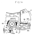
- the upper case 25 is opened and the imaging unit 11 is installed. Then, when the upper case 25 is closed, as shown in Fig. 3, the lever arms 65c of the pressure releasing lever 65 are pushed downward by the bottom surface of the housing 30 containing the imaging unit 11. Therein, the pressure releasing lever 65 is rotated clockwise in Fig. 3 against the elastic force of the spring 66, turning (each) cam 65b off of the bearing 62 knobs 62a supporting the pressure roller 51. Thereupon, the pressure roller 51 is impelled upward by the spring 63, whereby the rollers 50 and 51 are pressed together.
- the bottom portion of the imaging unit 11 is pushed upward by the lever arms 65c of the pressure releasing levers 65, locking the retainers 33 of the housing 30 into position abutting on the pins 34.
- the upper case 25 is opened, releasing pressure from the lever arm 65c such that a gap between the photoconductive drum 35 and the developing roller 12 is increased, preventing collision between the developing roller 12 and the photoconductive drum 35 as the imaging unit 11 is installed or dismounted.
- the heating roller 50 is automatically pressed against the pressure roller 51 through the mounting operation of the imaging unit 11, setting up time is reduced in comparison with conventional equipment using, for example, a shipping spacer to separate the rollers. Additionally, problems caused by error in installation are avoided. Furthermore, since the rotation center of the pressure releasing lever 65 coincides with the axis of the heating roller 50, a center rod for the lever 65 is not necessary, simplifying the pressure-releasing mechanism. Moreover still, providing the cam 65b with a gentle slope separates the roller pair with a small force through the rotation of the pressure-releasing mechanism.
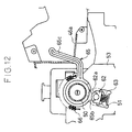
- the upper case 25 is opened as shown in Fig. 13.
- the pressure releasing lever 65 is rotated counterclockwise in Fig. 3, as is likewise the case wherein the imaging unit 11 is not in installation.
- the cam 65b thus forces the pressure roller 51 apart from the heating roller 50. In this state, the sheet jammed in the image fixing and sheet transporting unit 16 can be easily removed.
- the laser unit 15 optically discharges the electrostatically charged surface of the photoconductive drum 35, forming an according latent image thereon.
- the electrostatic latent image is developed as a toner image by the developing unit 14.
- the toner image is transferred onto the surface of the printing sheet by the transfer roller 40.
- the sheet is introduced into the image fixing and sheet transporting unit 16 along the sheet transport guide 45. Meanwhile, positively charged residual toner has collected in the residual toner container 37 of the imaging unit 11 housing 30.
- the sheet in being passed through the transfer roller 40 is charged with electricity of polarity opposite that of the toner. If the transfer guide 45 were a good conductor, it would abruptly drain the electric charge on the sheet, breaking adhesion of the unfixed toner to the sheet, and thus damaging in transport the image carried on its surface. In this embodiment of the present invention, however, since the sheet transport guide 45 is formed of a resin having controlled conductivity, the superficial resistivity being within the range previously mentioned, the electric charge on the sheet is drained only gradually through the sheet transport guide 45.
- the sheet transport guide 45 is of greater length, wherein its the surface resistivity is set at the specified value, damage to the unfixed toner-printed image due to abrupt draining of the electric charge during transportation is prevented.
- Residual toner collected in the container 37 of the housing 30 is positively charged.
- the middle frame 46 since the middle frame 46 is grounded, the middle frame 46 is negatively charged by electrostatic induction. Since the negative charge on the sheet traveling on the sheet transport guide 45 drains gradually as described above, electrostatic attraction between the sheet and the residual toner in the container 37 is reduced, whereby the sheet is prevented from curling upward. Consequently, sheet transport is stabilized.
- the thus transported sheet is guided to the transport guide 52e and the guide 71a of the catch 71 in the upper housing 52, wherein it is introduced between the heating roller 50 and the pressure roller 51.
- the sheet is then heated between the rollers 50 and 51 at a set pressure thereby fixing the toner image onto the surface of the sheet.
- the channel 54a of the mounting member 54 is immediate the heating roller 50. Therefore, wherein the printing operation continues, the water in the recess 54a is evaporated by heat from the heating roller 50. By this time, since the image forming equipment has warmed up sufficiently, any vapor reaching the partition 47 again will not condense into dew.
- the water storing capacity of the mounting member 54 channel 54a is sufficient to enable it to store the greatest quantity of dew condensation therein possible under normal operating conditions, no waterdrops will fall onto other items, such as the surface of the printing sheet, ensuring that water damage to the image is prevented.
- employing the partition 47 and the mounting member 54 eliminates the need to use a special element such as a hygroscopic material.
- the printing sheet After the printing sheet has undergone the image fixing operation, it is separated from the heating roller 50 by the separating claws 57 and then discharged onto the discharge tray by the discharge rollers 75 and 76. Therein, the trailing edge of the sheet enters a groove 76a of the lower roller 76, as shown in Fig. 8. Since the adjacent side of the groove 76a makes an acute angle with the line tangent to the cylindrical periphery, the trailing edge of the sheet further enters inside the groove 76a following the rotation of the lower roller 76. Thereby, the sheet is securely discharged into the discharge tray 17. In addition, since the cylindrical surface of the lower roller 76 is a arced, the sheet is further protected from being damaged.
Landscapes
- Physics & Mathematics (AREA)
- General Physics & Mathematics (AREA)
- Electrostatic Charge, Transfer And Separation In Electrography (AREA)
- Feeding Of Articles By Means Other Than Belts Or Rollers (AREA)
- Fixing For Electrophotography (AREA)
- Paper Feeding For Electrophotography (AREA)
- Cleaning In Electrography (AREA)
- Electrophotography Configuration And Component (AREA)
- Delivering By Means Of Belts And Rollers (AREA)
Applications Claiming Priority (2)
| Application Number | Priority Date | Filing Date | Title |
|---|---|---|---|
| JP4185137A JPH0627845A (ja) | 1992-07-13 | 1992-07-13 | 画像形成装置 |
| JP185137/92 | 1992-07-13 |
Publications (2)
| Publication Number | Publication Date |
|---|---|
| EP0579176A2 true EP0579176A2 (fr) | 1994-01-19 |
| EP0579176A3 EP0579176A3 (fr) | 1995-03-29 |
Family
ID=16165525
Family Applications (1)
| Application Number | Title | Priority Date | Filing Date |
|---|---|---|---|
| EP93111212A Withdrawn EP0579176A3 (fr) | 1992-07-13 | 1993-07-13 | Imprimante et machine de traitement de feuilles xérographique. |
Country Status (3)
| Country | Link |
|---|---|
| US (1) | US5579097A (fr) |
| EP (1) | EP0579176A3 (fr) |
| JP (1) | JPH0627845A (fr) |
Cited By (3)
| Publication number | Priority date | Publication date | Assignee | Title |
|---|---|---|---|---|
| DE10023614A1 (de) * | 2000-05-15 | 2001-11-22 | Nexpress Solutions Llc | Vorrichtung zum manuellen Austauschen einer Walze eines Vervielfältigungsgerätes |
| EP1184745A3 (fr) * | 2000-08-31 | 2005-01-05 | Hitachi, Ltd. | Système électrophotographique de formation d'images |
| EP2713218A3 (fr) * | 2012-09-04 | 2018-01-24 | Canon Kabushiki Kaisha | Appareil de fixation et appareil de formation d'images |
Families Citing this family (12)
| Publication number | Priority date | Publication date | Assignee | Title |
|---|---|---|---|---|
| DE19736437C2 (de) * | 1997-08-21 | 2000-12-14 | Oce Printing Systems Gmbh | Vorrichtung zum Abstreifen eines Aufzeichnungsträgers von der Oberfläche einer Walze in einem elektrofotografischen Druck- oder Kopiergerät |
| US6522858B1 (en) | 2000-10-04 | 2003-02-18 | Heidelberger Druckmaschinen Ag | Upper skive plate and method of installation in the fuser section of an electrophotographic machine |
| JP2004046081A (ja) * | 2002-05-17 | 2004-02-12 | Ricoh Co Ltd | 定着装置、および画像形成装置 |
| US6647215B1 (en) * | 2002-07-08 | 2003-11-11 | Hewlett-Packard Development Company, Lp. | System and method for detecting presence of a shipping insert of a printing device |
| US7013572B1 (en) * | 2003-03-31 | 2006-03-21 | Eastman Kodak Company | Skive plate assembly |
| JP2007127677A (ja) * | 2005-10-31 | 2007-05-24 | Ricoh Co Ltd | ガイド部材および画像形成装置 |
| JP5009067B2 (ja) * | 2007-07-04 | 2012-08-22 | 株式会社リコー | 定着装置及び画像形成装置 |
| JP5065831B2 (ja) * | 2007-09-27 | 2012-11-07 | 株式会社東芝 | 消去装置 |
| US8364051B2 (en) * | 2009-03-17 | 2013-01-29 | Ricoh Company, Ltd. | Fixing device and image forming apparatus including same |
| JP5829638B2 (ja) * | 2013-02-08 | 2015-12-09 | 株式会社沖データ | 定着装置及び画像形成装置 |
| JP6460047B2 (ja) * | 2016-05-20 | 2019-01-30 | 京セラドキュメントソリューションズ株式会社 | 定着装置およびそれを備えた画像形成装置 |
| JP7190348B2 (ja) * | 2018-12-27 | 2022-12-15 | シャープ株式会社 | 画像形成装置 |
Family Cites Families (30)
| Publication number | Priority date | Publication date | Assignee | Title |
|---|---|---|---|---|
| SU705411A1 (ru) * | 1978-06-19 | 1979-12-25 | Специальное Конструкторское Бюро Оргтехники | Устройство дл закреплени электрофотограческого порошкового изображени |
| US4369729A (en) * | 1980-08-18 | 1983-01-25 | Canon Kabushiki Kaisha | Image recording apparatus |
| JPS5772562A (en) * | 1980-10-20 | 1982-05-06 | Fuji Xerox Co Ltd | Paper inverting device |
| JPS5863972A (ja) * | 1981-10-13 | 1983-04-16 | Canon Inc | 熱定着器の安全装置 |
| JPS5955454A (ja) * | 1982-09-24 | 1984-03-30 | Fuji Xerox Co Ltd | 複写機用コピ−用紙搬送装置 |
| JPS59125764A (ja) * | 1983-01-07 | 1984-07-20 | Canon Inc | 転写式画像形成装置 |
| JPS59210461A (ja) * | 1983-05-13 | 1984-11-29 | Canon Inc | 乾式現像方式画像形成装置 |
| JPS6049375A (ja) * | 1983-08-29 | 1985-03-18 | Toshiba Corp | 画像形成装置 |
| JPS6190181A (ja) * | 1984-10-09 | 1986-05-08 | Olympus Optical Co Ltd | 圧接ロ−ラ−対の接離機構 |
| JPS61107276A (ja) * | 1984-10-30 | 1986-05-26 | Hitachi Metals Ltd | 加熱定着装置 |
| JPS61163363A (ja) * | 1985-01-14 | 1986-07-24 | Canon Inc | クリ−ニング装置 |
| JPH0717295B2 (ja) * | 1986-03-28 | 1995-03-01 | キヤノン株式会社 | 画像形成装置 |
| JPS63146086A (ja) * | 1986-12-10 | 1988-06-18 | Toshiba Corp | 記録装置 |
| JPS63244085A (ja) * | 1987-03-31 | 1988-10-11 | Toshiba Corp | 画像形成装置 |
| JPH01108589A (ja) * | 1987-10-22 | 1989-04-25 | Yuniko Kk | ヒートロール定着用加圧ロール及びヒートロール定着装置 |
| JPH01185686A (ja) * | 1988-01-20 | 1989-07-25 | Canon Inc | 画像形成装置 |
| JPH0223147A (ja) * | 1988-07-12 | 1990-01-25 | Mita Ind Co Ltd | 用紙排出装置 |
| JPH02234179A (ja) * | 1989-03-07 | 1990-09-17 | Toshiba Corp | 画像形成装置 |
| JPH0343776A (ja) * | 1989-07-11 | 1991-02-25 | Ricoh Co Ltd | 加熱ローラー型定着装置の温度制御装置 |
| JPH03228074A (ja) * | 1989-08-09 | 1991-10-09 | Ricoh Co Ltd | 転写体搬送案内部材 |
| US4958195A (en) * | 1989-08-25 | 1990-09-18 | International Business Machines Corporation | Method and apparatus for fusing envelopes |
| JPH03100566A (ja) * | 1989-09-13 | 1991-04-25 | Ricoh Co Ltd | 電子写真装置 |
| JPH03249681A (ja) * | 1990-02-28 | 1991-11-07 | Toshiba Corp | 定着装置 |
| JPH04166953A (ja) * | 1990-10-31 | 1992-06-12 | Konica Corp | 画像形成装置 |
| JP2840483B2 (ja) * | 1991-06-28 | 1998-12-24 | キヤノン株式会社 | 画像形成装置 |
| JPH056123A (ja) * | 1991-06-28 | 1993-01-14 | Canon Inc | 記録材搬送装置 |
| JPH0572938A (ja) * | 1991-09-13 | 1993-03-26 | Tokyo Electric Co Ltd | 画像形成装置の定着装置 |
| JP3187493B2 (ja) * | 1991-12-11 | 2001-07-11 | 株式会社リコー | 用紙排出装置 |
| JPH05224547A (ja) * | 1992-02-14 | 1993-09-03 | Fuji Xerox Co Ltd | 転写紙搬送装置 |
| JP3124832B2 (ja) * | 1992-06-18 | 2001-01-15 | キヤノン株式会社 | 定着装置 |
-
1992
- 1992-07-13 JP JP4185137A patent/JPH0627845A/ja active Pending
-
1993
- 1993-07-12 US US08/089,377 patent/US5579097A/en not_active Expired - Lifetime
- 1993-07-13 EP EP93111212A patent/EP0579176A3/fr not_active Withdrawn
Cited By (3)
| Publication number | Priority date | Publication date | Assignee | Title |
|---|---|---|---|---|
| DE10023614A1 (de) * | 2000-05-15 | 2001-11-22 | Nexpress Solutions Llc | Vorrichtung zum manuellen Austauschen einer Walze eines Vervielfältigungsgerätes |
| EP1184745A3 (fr) * | 2000-08-31 | 2005-01-05 | Hitachi, Ltd. | Système électrophotographique de formation d'images |
| EP2713218A3 (fr) * | 2012-09-04 | 2018-01-24 | Canon Kabushiki Kaisha | Appareil de fixation et appareil de formation d'images |
Also Published As
| Publication number | Publication date |
|---|---|
| JPH0627845A (ja) | 1994-02-04 |
| EP0579176A3 (fr) | 1995-03-29 |
| US5579097A (en) | 1996-11-26 |
Similar Documents
| Publication | Publication Date | Title |
|---|---|---|
| US5579097A (en) | Xerographic printing and sheet processing apparatus | |
| CN100392533C (zh) | 成像设备及分离构件 | |
| US4965640A (en) | Image forming apparatus including detachable toner fixing unit | |
| US5539509A (en) | Sheet transportation system in magnetic-toner xerographic image fixing apparatus | |
| US5722012A (en) | Image forming apparatus | |
| US5671466A (en) | Electrophotographic apparatus and sheet guide mechanism | |
| US5276489A (en) | Image forming apparatus with transfer roller with guide means which adjusts to movements of the roller | |
| JP2576538Y2 (ja) | 電子写真装置用プロセスカートリッジの装着機構 | |
| US5614997A (en) | Transfer device configuration in an image-reproducing station | |
| JP3159047B2 (ja) | 画像形成装置における搬送ガイド装置 | |
| US4769670A (en) | Transfer sheet guiding device | |
| US5689775A (en) | Transfer device configuration in an image-reproducing station | |
| JP2711050B2 (ja) | 画像形成装置のユニット固定構造 | |
| JP2664313B2 (ja) | 定着装置を有する画像形成装置 | |
| JP2643726B2 (ja) | シート搬送装置 | |
| JP2664314B2 (ja) | 定着装置 | |
| JP2783306B2 (ja) | 画像形成装置のユニット取り付け構造 | |
| JP2968345B2 (ja) | 電子写真装置の定着器 | |
| US5923927A (en) | Brackets and one piece frames for a toner fixing device in an electrophotographic apparatus | |
| JP2592568B2 (ja) | 画像形成装置のシート搬送装置 | |
| KR200149602Y1 (ko) | 레이져 빔 프린터의 용지사행 보정구조 | |
| JP3501900B2 (ja) | 画像形成装置 | |
| KR100202381B1 (ko) | 전자사진 프로세서의 기록용지 급지 장치 | |
| JPH0627852A (ja) | 定着装置の剥離爪装置 | |
| JP2988953B2 (ja) | 電子写真装置のコロナチャージャ |
Legal Events
| Date | Code | Title | Description |
|---|---|---|---|
| PUAI | Public reference made under article 153(3) epc to a published international application that has entered the european phase |
Free format text: ORIGINAL CODE: 0009012 |
|
| AK | Designated contracting states |
Kind code of ref document: A2 Designated state(s): DE FR GB IT |
|
| PUAL | Search report despatched |
Free format text: ORIGINAL CODE: 0009013 |
|
| AK | Designated contracting states |
Kind code of ref document: A3 Designated state(s): DE FR GB IT |
|
| 17P | Request for examination filed |
Effective date: 19950628 |
|
| 17Q | First examination report despatched |
Effective date: 19950725 |
|
| STAA | Information on the status of an ep patent application or granted ep patent |
Free format text: STATUS: THE APPLICATION IS DEEMED TO BE WITHDRAWN |
|
| 18D | Application deemed to be withdrawn |
Effective date: 19960509 |