EP0579477B1 - Dispositif de coupe pour papier ayant un disque de coupe mobile - Google Patents
Dispositif de coupe pour papier ayant un disque de coupe mobile Download PDFInfo
- Publication number
- EP0579477B1 EP0579477B1 EP93305472A EP93305472A EP0579477B1 EP 0579477 B1 EP0579477 B1 EP 0579477B1 EP 93305472 A EP93305472 A EP 93305472A EP 93305472 A EP93305472 A EP 93305472A EP 0579477 B1 EP0579477 B1 EP 0579477B1
- Authority
- EP
- European Patent Office
- Prior art keywords
- paper
- cutter
- stationary
- cutting
- movable
- Prior art date
- Legal status (The legal status is an assumption and is not a legal conclusion. Google has not performed a legal analysis and makes no representation as to the accuracy of the status listed.)
- Expired - Lifetime
Links
- 238000005520 cutting process Methods 0.000 title claims description 121
- 230000002093 peripheral effect Effects 0.000 claims description 2
- 230000008878 coupling Effects 0.000 description 4
- 238000010168 coupling process Methods 0.000 description 4
- 238000005859 coupling reaction Methods 0.000 description 4
- 239000002390 adhesive tape Substances 0.000 description 1
- 238000010276 construction Methods 0.000 description 1
- 239000000463 material Substances 0.000 description 1
- 230000000717 retained effect Effects 0.000 description 1
Images




Classifications
-
- H—ELECTRICITY
- H04—ELECTRIC COMMUNICATION TECHNIQUE
- H04N—PICTORIAL COMMUNICATION, e.g. TELEVISION
- H04N1/00—Scanning, transmission or reproduction of documents or the like, e.g. facsimile transmission; Details thereof
-
- B—PERFORMING OPERATIONS; TRANSPORTING
- B41—PRINTING; LINING MACHINES; TYPEWRITERS; STAMPS
- B41J—TYPEWRITERS; SELECTIVE PRINTING MECHANISMS, i.e. MECHANISMS PRINTING OTHERWISE THAN FROM A FORME; CORRECTION OF TYPOGRAPHICAL ERRORS
- B41J15/00—Devices or arrangements of selective printing mechanisms, e.g. ink-jet printers or thermal printers, specially adapted for supporting or handling copy material in continuous form, e.g. webs
- B41J15/04—Supporting, feeding, or guiding devices; Mountings for web rolls or spindles
- B41J15/042—Supporting, feeding, or guiding devices; Mountings for web rolls or spindles for loading rolled-up continuous copy material into printers, e.g. for replacing a used-up paper roll; Point-of-sale printers with openable casings allowing access to the rolled-up continuous copy material
-
- B—PERFORMING OPERATIONS; TRANSPORTING
- B26—HAND CUTTING TOOLS; CUTTING; SEVERING
- B26D—CUTTING; DETAILS COMMON TO MACHINES FOR PERFORATING, PUNCHING, CUTTING-OUT, STAMPING-OUT OR SEVERING
- B26D1/00—Cutting through work characterised by the nature or movement of the cutting member or particular materials not otherwise provided for; Apparatus or machines therefor; Cutting members therefor
- B26D1/01—Cutting through work characterised by the nature or movement of the cutting member or particular materials not otherwise provided for; Apparatus or machines therefor; Cutting members therefor involving a cutting member which does not travel with the work
- B26D1/12—Cutting through work characterised by the nature or movement of the cutting member or particular materials not otherwise provided for; Apparatus or machines therefor; Cutting members therefor involving a cutting member which does not travel with the work having a cutting member moving about an axis
- B26D1/14—Cutting through work characterised by the nature or movement of the cutting member or particular materials not otherwise provided for; Apparatus or machines therefor; Cutting members therefor involving a cutting member which does not travel with the work having a cutting member moving about an axis with a circular cutting member, e.g. disc cutter
- B26D1/20—Cutting through work characterised by the nature or movement of the cutting member or particular materials not otherwise provided for; Apparatus or machines therefor; Cutting members therefor involving a cutting member which does not travel with the work having a cutting member moving about an axis with a circular cutting member, e.g. disc cutter coacting with a fixed member
- B26D1/205—Cutting through work characterised by the nature or movement of the cutting member or particular materials not otherwise provided for; Apparatus or machines therefor; Cutting members therefor involving a cutting member which does not travel with the work having a cutting member moving about an axis with a circular cutting member, e.g. disc cutter coacting with a fixed member for thin material, e.g. for sheets, strips or the like
-
- B—PERFORMING OPERATIONS; TRANSPORTING
- B26—HAND CUTTING TOOLS; CUTTING; SEVERING
- B26D—CUTTING; DETAILS COMMON TO MACHINES FOR PERFORATING, PUNCHING, CUTTING-OUT, STAMPING-OUT OR SEVERING
- B26D7/00—Details of apparatus for cutting, cutting-out, stamping-out, punching, perforating, or severing by means other than cutting
- B26D7/18—Means for removing cut-out material or waste
-
- B—PERFORMING OPERATIONS; TRANSPORTING
- B41—PRINTING; LINING MACHINES; TYPEWRITERS; STAMPS
- B41J—TYPEWRITERS; SELECTIVE PRINTING MECHANISMS, i.e. MECHANISMS PRINTING OTHERWISE THAN FROM A FORME; CORRECTION OF TYPOGRAPHICAL ERRORS
- B41J11/00—Devices or arrangements of selective printing mechanisms, e.g. ink-jet printers or thermal printers, for supporting or handling copy material in sheet or web form
- B41J11/66—Applications of cutting devices
- B41J11/70—Applications of cutting devices cutting perpendicular to the direction of paper feed
- B41J11/706—Applications of cutting devices cutting perpendicular to the direction of paper feed using a cutting tool mounted on a reciprocating carrier
-
- Y—GENERAL TAGGING OF NEW TECHNOLOGICAL DEVELOPMENTS; GENERAL TAGGING OF CROSS-SECTIONAL TECHNOLOGIES SPANNING OVER SEVERAL SECTIONS OF THE IPC; TECHNICAL SUBJECTS COVERED BY FORMER USPC CROSS-REFERENCE ART COLLECTIONS [XRACs] AND DIGESTS
- Y10—TECHNICAL SUBJECTS COVERED BY FORMER USPC
- Y10T—TECHNICAL SUBJECTS COVERED BY FORMER US CLASSIFICATION
- Y10T83/00—Cutting
- Y10T83/202—With product handling means
- Y10T83/2074—Including means to divert one portion of product from another
- Y10T83/2083—Deflecting guide
-
- Y—GENERAL TAGGING OF NEW TECHNOLOGICAL DEVELOPMENTS; GENERAL TAGGING OF CROSS-SECTIONAL TECHNOLOGIES SPANNING OVER SEVERAL SECTIONS OF THE IPC; TECHNICAL SUBJECTS COVERED BY FORMER USPC CROSS-REFERENCE ART COLLECTIONS [XRACs] AND DIGESTS
- Y10—TECHNICAL SUBJECTS COVERED BY FORMER USPC
- Y10T—TECHNICAL SUBJECTS COVERED BY FORMER US CLASSIFICATION
- Y10T83/00—Cutting
- Y10T83/202—With product handling means
- Y10T83/2092—Means to move, guide, or permit free fall or flight of product
- Y10T83/2209—Guide
-
- Y—GENERAL TAGGING OF NEW TECHNOLOGICAL DEVELOPMENTS; GENERAL TAGGING OF CROSS-SECTIONAL TECHNOLOGIES SPANNING OVER SEVERAL SECTIONS OF THE IPC; TECHNICAL SUBJECTS COVERED BY FORMER USPC CROSS-REFERENCE ART COLLECTIONS [XRACs] AND DIGESTS
- Y10—TECHNICAL SUBJECTS COVERED BY FORMER USPC
- Y10T—TECHNICAL SUBJECTS COVERED BY FORMER US CLASSIFICATION
- Y10T83/00—Cutting
- Y10T83/768—Rotatable disc tool pair or tool and carrier
- Y10T83/7755—Carrier for rotatable tool movable during cutting
- Y10T83/7763—Tool carrier reciprocable rectilinearly
- Y10T83/7776—With means to reciprocate carrier
-
- Y—GENERAL TAGGING OF NEW TECHNOLOGICAL DEVELOPMENTS; GENERAL TAGGING OF CROSS-SECTIONAL TECHNOLOGIES SPANNING OVER SEVERAL SECTIONS OF THE IPC; TECHNICAL SUBJECTS COVERED BY FORMER USPC CROSS-REFERENCE ART COLLECTIONS [XRACs] AND DIGESTS
- Y10—TECHNICAL SUBJECTS COVERED BY FORMER USPC
- Y10T—TECHNICAL SUBJECTS COVERED BY FORMER US CLASSIFICATION
- Y10T83/00—Cutting
- Y10T83/768—Rotatable disc tool pair or tool and carrier
- Y10T83/7863—Tool pair comprises rotatable tool and nonrotatable tool
-
- Y—GENERAL TAGGING OF NEW TECHNOLOGICAL DEVELOPMENTS; GENERAL TAGGING OF CROSS-SECTIONAL TECHNOLOGIES SPANNING OVER SEVERAL SECTIONS OF THE IPC; TECHNICAL SUBJECTS COVERED BY FORMER USPC CROSS-REFERENCE ART COLLECTIONS [XRACs] AND DIGESTS
- Y10—TECHNICAL SUBJECTS COVERED BY FORMER USPC
- Y10T—TECHNICAL SUBJECTS COVERED BY FORMER US CLASSIFICATION
- Y10T83/00—Cutting
- Y10T83/869—Means to drive or to guide tool
- Y10T83/8821—With simple rectilinear reciprocating motion only
- Y10T83/8822—Edge-to-edge of sheet or web [e.g., traveling cutter]
Definitions
- the present invention relates to a paper cutting device, for use in a facsimile machine, copier, printer, or the like for cutting paper discharged from a roll at a predetermined length, and more particularly, to a paper cutting device including an elongate stationary cutter and a movable cutter which is movable along the stationary cutter to thereby cut the paper.
- Conventional copiers, printers, facsimile machines and the like include a paper cutting device for cutting paper discharged from a roll page by page.
- a conventional paper cutting device is illustrated in Fig. 1.
- Such a device includes an elongated stationary cutter 21 having a stationary cutting edge and a movable cutter 22 having a movable cutting edge and being movable along the stationary cutter while being urged thereagainst so that the cutting edges cooperate to cut the paper.
- a rotary cutting wheel 22 is used as the movable cutter and is positioned so that its peripheral cutting edge slightly overlaps the cutting edge of the stationary cutter 21 thereby cutting the paper as it is discharged from the roll.
- the cutting wheel 22 is rotatably held by a carriage 23 which is movable on and along a guide rail 24a of an elongate guide plate 24 disposed parallel to the stationary cutter 21. There is a narrow gap 25 between the elongate guide plate 24 and the stationary cutter 21 in which the paper, discharged from the roll, is inserted to hold the paper while the cutting wheel 22 is moved along the stationary cutter 21.
- the carriage 23 In order to move the cutting wheel along the guide rail 24a, the carriage 23 is fixed to a wire 27 which is disposed between pulleys 28a and 28b.
- the pulley 28a is coupled to a motor 29 to transmit a rotation force from the motor 29 to the wire 27.
- a frame 26 holds the stationary cutter 21, guide plate 24, pulleys 28a, 28b and motor 29, as illustrated in Fig. 1.
- the paper is cut in the following manner. As noted above, the paper 10 is inserted into the gap 25 from the back of the frame 26 so that the paper is retained therein during a cutting operation. When the cutting wheel carriage 23 moves from one end of the guide rail 24a to the other end, the cutting wheel 22 in cooperation with the stationary cutter 21 cuts the paper 10.
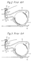
- Fig. 2 shows a printing mechanism of a facsimile receiver which uses the conventional paper cutting device of Fig. 1.
- a thermal sensing paper roll 10a is disposed in a case 41 which is fixed on a base 40.
- a cover 42 is located over the case 41.
- a platen roller 44 is coupled to the cover 42 and contacts a thermal head 43 with the paper disposed therebetween so as to record information on the paper 10 discharged from the thermal sensing paper roll 10a.
- the platen roller 44 rotates to transmit the paper 10 via paper guide plates 45 into the gap 25 defined by the stationary cutter 21 and the guide plate 24 and the paper is cut, as shown in Fig. 3.
- the paper roll 10a when the paper roll 10a is put in the case 41 after removing the cover 42, the paper 10 has to be inserted between the guide plates 45 and then fed into the gap 25.
- the end of the paper 10 when feeding the paper, the end of the paper 10 is sometimes obstructed at the entrance of the gap 25 because the gap 25 is too narrow.
- the gap 25 is widened in an effort to overcome the above problems associated with inserting the paper and unjamming the paper, the paper cannot be cut properly because the paper 10 floats and tends to curl in the gap during cutting, which causes the paper to jam.
- German Patent DE-C-876386 discloses a paper cutting device comprising a stationary cutter and a manually operated movable cutter, wherein the movable cutter and stationary cutter have respective cutting edges which cooperate with each other to cut the paper and a guide member guides the paper towards the cutting position.
- a further example of such a cutting device is that disclosed in United States Patent US-A-3447409 which discloses a paper cutter in which a movable cutter cooperates with a stationary cutter to cut paper at a momentaneous cutting position, the movable cutter being mounted on an arm of a movable carriage.
- a plow portion guides the paper to the cutting position without pressing the paper to a stationary cutter, and said movable cutter and said plow portion are disposed proximate to an opposite side of a surface on which moving means are disposed.
- An arm has a concave portion through which a cut portion of the paper is fed, to separate the cut portion from the uncut portion.
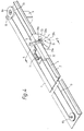
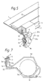
- Fig. 4 is a perspective view of a paper cutting device of a preferred embodiment of the present invention and Fig. 5 is sectional view taken along line 5-5 of Fig. 4.
- an elongate, straight stationary cutter 2 having a cutting edge is positioned on a side portion of a flat cutter frame 1, and is affixed thereto by double sided adhesive tape or similar affixing material so as to extend parallel to the longitudinal direction of the frame 1.
- An edge of the cutter frame 1 is bent upwardly to form an upright guide rail 4 disposed above the stationary cutting member 2.
- a carriage 3 is connected to the guide rail 4 by a holder 32 which is slidably disposed on the guide rail 4 so that the carriage can be moved in the longitudinal direction of the stationary cutter 2.
- the carriage 3 includes the slidable holder 32 and a generally L-shaped arm 33 secured to the slidable holder 32 and hanging downwardly therefrom.
- a cutting wheel 5 is rotatably supported thereon and constitutes the movable cutter which, in cooperation with the stationary cutter 2, cuts the paper as described below.
- the arm 33 includes a front plow portion 33a, rear plow portion 33b and bottom plow portion 33c and defines a curved concave portion 33d illustrated in Fig. 4.
- the plow portions 33a - 33c are disposed below the stationary cutter 2.
- a pin 31 is fixed to the arm 33 proximate the plow portions and has a bearing 34 rotatably disposed thereon, as shown in Fig. 5.
- the cutting wheel 5 is coupled to the bearing 34 so as to be rotatable about the pin 31 via the bearing 34.
- the edge of the cutting wheel 5 slightly overlaps the cutting edge of the stationary cutter 2.
- a pressure plate 35 is integrally secured to the cutting wheel 5 so as to be rotatable therewith.
- the outer edge of the pressure plate 35 is pressed upright against the bottom of the stationary cutting member 2 by the arm 33.
- a rotational force acts on the cutting wheel 5 due to the friction between the bottom of the stationary cutting member 2 and the pressure plate 35.
- a resilient plate 36 is inserted in the pin 31 and the plate 36 pushes the bearing 34 to urge the edge of the cutting wheel 5 to the stationary cutting member 2.
- the front plow portion 33a is disposed forwardly of the cutting position between the stationary cutter 2 and cutting wheel 5 and inclines downwardly.
- the curved concave portion 33d is located slightly rearwardly of the cutting position and is curved downward.
- a curved surface 33e which partially defines the curved concave portion 33d, faces in the direction of arrow B in Fig. 5, and is inclined with respect to the stationary cutter 2.
- the curved concave portion 33d and the curved surface 33e are provided for the purpose of separating the paper cut at the cutting position between the stationary cutter 2 and the cutting wheel 5 and urging the cut portion of the paper toward the outside of the carriage 3.
- a connection portion of the arm 33 for connecting the arm to the moving means 8a, 8b, 9, 10 is disposed on the other side of the movable cutter 5 seen in a direction parallel to the stationary cutting edge, and has a slot with a curved inner surface 33e merging with the surface of the plow portion at a location of the movable cutting edge, the slot being concave in such manner that it widens in a direction parallel to the first surface and perpendicular to the stationary cutting edge.
- two pulleys 8a and 8b are mounted on opposite ends of the cutter frame 1 in the longitudinal direction of the stationary cutter 2.
- the pulley 8a is rotated by a motor 9 via a pinion gear 12 mounted on an output shaft of the motor 9 and a gear 13.
- a wire 10 circumscribes the pulleys 8a and 8b and is held under tension by a coil spring 7 to serve as a medium for driving the cutting wheel carriage 3.
- the slidable holder 32 of the carriage 3 is connected to the wire 10 at a predetermined position.
- the motor 9 When the motor 9 is energized, the rotation of the motor 9 is transmitted to the pulley 8a via the pinion gear 12 and gear 13.
- the pulley 8a causes the wire 10 and, therefore, the carriage 3 to reciprocate back and forth along the guide rail 4.
- the pulleys 8a, 8b, the motor 9 and wire 10 comprise moving means disposed on the second surface.
- the movable cutter is substantially disposed on the same side of the first surface as the plow portion and overlapping with the stationary cutting edge at the momentaneous cutting position for cooperation with the stationary cutting edge to cut the paper.
- the carriage 3 is located at a home position which is located at the right-hand side (motor side) of the cutter frame 1. Paper (not shown) is fed under the cutter frame 1 to the stationary cutting member 2.
- the front plow portion 33a guides the edge of the paper toward the cutting position where the stationary cutter 2 and cutting wheel 5 overlap.
- the cut paper is passed through the curved concave portion 33d so that it contacts the curved surface 33e and is fed outwardly of the arm 33.
- Fig. 6 is a perspective view of a printing device used in a facsimile machine which includes the paper cutting device of Fig. 4, and Fig. 7 is a sectioned view of the printing device of Fig. 6.
- the thermal sensing paper roll 10a is disposed in a case 51.
- a cover 52 is located over the case 51, and one end of the cover 52 is connected to a bar 53 so that the cover 52 can pivot about the bar 53 between opened and closed positions.
- a platen roller 54 is coupled to the cover 52 and rotates under the cover 52. Although a coupling mechanism between the platen roller 54 and the cover 52 is not shown in the Figures, various support members and bearings are used as the coupling mechanism. The specific construction of the coupling mechanism would be obvious to a person of ordinary skill in the art.
- the platen 54 presses the paper unwound from the paper roll 10a against a thermal head 55 to record or print information on the paper and transmits the paper 10 to a guide plate 56.
- One end of the platen roller 54 is provided with a gear 62 which is rotated by a motor 60 via gears 61.
- the guide plate 56 faces a guide portion 52a of the cover 52 to guide the paper 10 under the cutter frame 1, as best illustrated in Fig. 7.
- the disk head carriage 3 When the paper roll 10a is positioned in the case 51, the disk head carriage 3 is disposed in the home position and the cover 52 along with the platen roller 54 is pivoted to an opened position as shown in Fig. 8. After the paper 10 is discharged from the roll 10a, the cover 52 is closed and the gear 62 is engaged with a gear 61. Then, a cutting operation is performed to cut an end portion of the paper 10.
- the front plow portion 33a of the arm 33 guides the side edge of the paper 10 to the cutting position between the stationary cutter 2 and cutting wheel 5 as described above. Therefore, it is not necessary to retain the paper 10 in a narrow gap, as in the conventional arrangement. This prevents the paper 10 from jamming in the cutting device. Further, even if the paper does jam, it is easy to remove the jammed paper by simply opening the cover 52.
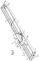
- Fig. 9 shows a paper cutting device according to another embodiment of the present invention.
- the only difference between the paper cutting device of Fig. 9 and the paper cutting device of Fig. 4 is the shape of the cutting wheel carriage 3 and 3' and the manner in which it is operated.
- the cutting device of Fig. 4 When the cutting device of Fig. 4 is used, paper is supplied from below the cutter frame 1 and the cut paper falls below the cutting frame 1 as shown in Figs. 6 to 8.
- the cutting device of Fig. 9 paper is supplied from above the cutter frame 1 and the cut paper falls below the cutting frame 1. Therefore, in the cutting device of Fig.
- the front plow portion 33a' of the arm 33' is positioned above the stationary cutter 2, and the rear plow portion 33b' and the bottom plow portion 33c' of the arm 33' are positioned below the stationary cutter 2.
- Each of the plow portions in Fig. 4 and Fig. 9 performs the same function.
- Fig. 10 and Fig. 11 show a printing mechanism for a facsimile machine which uses the cutting device of Fig. 9.
- a thermal sensing paper roll 10a is placed in a case 61 which is fixed on a housing 67.
- a cover 62 is disposed on the case 61 and rotates about an axis 65 between opened and closed positions.
- a thermal head 63 is disposed inside the cover 62 and is supported by support 64. When the cover 62 is closed as shown in Fig. 11, the thermal head 63 contacts a platen roller 66 which is located between the upper part of the case 61 and the cutting device.
- the paper 10 discharged from the paper roll 10a is nipped between the thermal head 63 and the platen roller 66, and then fed along the cutter frame 1 of the cutting device. Before the cutting operation, the carriage 3' is disposed at the home position on the motor side.
- the carriage 3' moves along the stationary cutter 2 to cut the paper 10. Since the edge of the paper 10 is guided toward the cutting position by the front plow portion 33a', the cutting operation is performed without experiencing paper jam. Also the curved concave portion 33d' and the curved surface 33e' separate the cut paper from the arm 33' in the same manner discussed above. When the carriage 3' reaches the opposite end from the home position, it returns to the home position and plow portion 33b' and bottom plow portion 33c' urge the cut paper downwardly.
- a moving device for moving the carriage 3 or 3' in a reciprocating motion along the guide rail 4 is implemented by the wire 10 passing over the two pulleys at longitudinal opposite ends of the stationary cutter 2.
- the pulleys and the wire 10 may be replaced with gears and a timing belt, respectively.
- the pulleys and the wire 10 may be replaced with a screw gear shaft which is disposed parallel to the stationary cutter 2.
- the screw gear shaft is used as the moving device, the carriage 3 is coupled to the screw gear shaft via a coupling gear and is moved by rotating the screw gear shaft. This mechanism is used in a moving device for moving a printer head carriage.
- a rotary cutting wheel 5 as the movable cutter
- other rotatable movable cutters may be used.
Landscapes
- Engineering & Computer Science (AREA)
- Life Sciences & Earth Sciences (AREA)
- Forests & Forestry (AREA)
- Mechanical Engineering (AREA)
- Multimedia (AREA)
- Signal Processing (AREA)
- Handling Of Sheets (AREA)
- Nonmetal Cutting Devices (AREA)
Claims (10)
- Dispositif de coupe pour papier comprenant une lame fixe (2) présentant une première surface et une seconde surface opposée à la première, et un bord de coupe fixe étant prévu sur un côté de ladite première surface à sa périphérie ;une lame mobile (5) pouvant se déplacer le long de ladite lame fixe (2) et présentant un bord de coupe mobile destiné à coopérer avec ledit bord de coupe fixe pour couper ledit papier au niveau d'une position de coupe ;un chariot mobile (3) qui comprend un bras (33), ledit bras disposé devant le bord de coupe de ladite lame fixe (2) sensiblement à l'extérieur de la périphérie de ladite première surface, et supportant en rotation ladite lame mobile ; etdes moyens de déplacement (8a, 8b, 9, 10) destinés à déplacer ledit chariot mobile (3) le long de ladite lame fixe (2), les moyens de déplacement étant disposés sur ladite lame fixe (2) et reliés audit chariot (3) au moyen d'une partie de liaison dudit bras (33), la partie de liaison comportant une fente qui s'étend depuis la lame mobile (5), caractérisé en ce que :ledit bras (33) dudit chariot mobile possède une partie de soc (33a) formée sur celui-ci afin de guider ledit papier vers la position de coupe ;ladite partie de soc (33a) est disposée au-delà d'un plan défini par ladite première surface vu dans le sens allant de ladite seconde à ladite première surface, et au niveau d'un côté de ladite lame mobile, vu dans une direction parallèle audit bord de coupe fixe, qui est opposé à l'emplacement de la partie de liaison dudit bras (33) comportant une fente avec une surface intérieure incurvée (33e) qui rejoint la surface de ladite partie de soc en un emplacement adjacent audit bord de coupe mobile, ladite fente étant concave, si bien qu'elle s'élargit dans une direction parallèle à ladite première surface et perpendiculaire audit bord de coupe fixe et en s'éloignant de celui-ci,lesdits moyens mobiles (8a, 8b, 9, 10) sont disposés sur ladite seconde surface, et ladite lame mobile (5) est sensiblement disposée du même côté de ladite première surface que ladite partie de soc (33a) et en chevauchement avec ledit bord de coupe fixe au niveau de la position de coupe momentanée pour permettre la coopération avec ledit bord de coupe fixe pour couper le papier.
- Dispositif de coupe pour papier selon la revendication 1, dans lequel ladite partie de soc est une première partie de soc (33a) et ledit bras comprend en outre une seconde partie de soc (33b) disposée à côté du bas dudit bras pour pousser une partie coupée dudit papier depuis une partie restante dudit papier lors d'une course arrière dudit chariot.
- Dispositif de coupe pour papier selon la revendication 2, dans lequel ladite première partie de soc (33a) et ladite seconde partie de soc (33b) dudit bras sont situées au-dessous de ladite lame fixe (2).
- Dispositif de coupe pour papier selon la revendication 2, dans lequel ladite première partie de soc (33a) et ladite seconde partie de soc (33b) dudit bras sont situées sur des côtés opposés par rapport à ladite lame mobile (5).
- Dispositif de coupe pour papier selon l'une quelconque des revendications 1 à 4, dans lequel ladite lame mobile est un disque de coupe rotatif (5) qui est soutenu en rotation par ledit bras (33).
- Dispositif de coupe pour papier selon la revendication 5, comprenant en outre des moyens de rotation (35) destinés à mettre en rotation ledit disque de coupe en réponse au déplacement dudit chariot par lesdits moyens de déplacement.
- Dispositif de coupe pour papier selon la revendication 6, dans lequel lesdits moyens de rotation comprennent un disque presseur (35) solidaire dudit disque de coupe (5) et disposé de telle manière qu'un bord périphérique dudit disque presseur soit poussé contre ladite lame fixe (2).
- Dispositif de coupe pour papier selon l'une quelconque des revendications précédentes, comprenant en outre un cadre de lames (1) auquel sont fixés ladite lame fixe (2) et lesdits moyens de déplacement (8a, 8b, 9, 10).
- Dispositif de coupe pour papier selon la revendication 8, dans lequel ledit cadre de lames (1) possède un guide (4) construit parallèle à ladite lame fixe pour guider ledit chariot mobile.
- Dispositif de coupe pour papier selon l'une quelconque des revendications précédentes, dans lequel lesdits moyens de déplacement comprennent deux poulies (8a, 8b) couplées audit cadre de lames (1), un câble (10) tendu entre lesdites poulies, et des moyens d'entraînement (9) pour mettre en rotation l'une desdites poulies de manière à déplacer ledit câble, ledit chariot mobile (3) étant fixé audit câble.
Applications Claiming Priority (2)
| Application Number | Priority Date | Filing Date | Title |
|---|---|---|---|
| JP186397/92 | 1992-07-14 | ||
| JP18639792 | 1992-07-14 |
Publications (2)
| Publication Number | Publication Date |
|---|---|
| EP0579477A1 EP0579477A1 (fr) | 1994-01-19 |
| EP0579477B1 true EP0579477B1 (fr) | 1997-10-01 |
Family
ID=16187689
Family Applications (1)
| Application Number | Title | Priority Date | Filing Date |
|---|---|---|---|
| EP93305472A Expired - Lifetime EP0579477B1 (fr) | 1992-07-14 | 1993-07-13 | Dispositif de coupe pour papier ayant un disque de coupe mobile |
Country Status (10)
| Country | Link |
|---|---|
| US (1) | US5431077A (fr) |
| EP (1) | EP0579477B1 (fr) |
| KR (1) | KR0137002B1 (fr) |
| CN (1) | CN1035865C (fr) |
| CA (1) | CA2100014C (fr) |
| DE (1) | DE69314250T2 (fr) |
| HK (1) | HK1001000A1 (fr) |
| MY (1) | MY108892A (fr) |
| PH (1) | PH30513A (fr) |
| SG (1) | SG43252A1 (fr) |
Families Citing this family (34)
| Publication number | Priority date | Publication date | Assignee | Title |
|---|---|---|---|---|
| JP2771761B2 (ja) * | 1993-10-08 | 1998-07-02 | 株式会社大西ライト工業所 | シート材の切断装置 |
| US5893204A (en) | 1996-11-12 | 1999-04-13 | Dresser Industries, Inc. | Production process for casting steel-bodied bits |
| US5572940A (en) * | 1994-05-27 | 1996-11-12 | Burton & Noonan | Folding and sewing apparatus |
| FR2729336B1 (fr) * | 1995-01-16 | 1997-04-04 | Sextant Avionique | Dispositif pour la decoupe, la predecoupe ou la perforation d'une feuille de papier |
| TW283819B (fr) * | 1995-02-03 | 1996-08-21 | Fuji Photo Film Co Ltd | |
| US5639506A (en) * | 1996-02-08 | 1997-06-17 | United States Surgical Corporation | Rotary suture cutting apparatus and method of use |
| JP3364779B2 (ja) * | 1996-05-31 | 2003-01-08 | 日本電気エンジニアリング株式会社 | カッター機構 |
| JP3212876B2 (ja) * | 1996-06-20 | 2001-09-25 | 株式会社大西ライト工業所 | 移動体の反転機構およびその反転機構を利用したシート材切断装置の刃物台往復動機構 |
| JPH106279A (ja) * | 1996-06-21 | 1998-01-13 | Nec Eng Ltd | カッター機構 |
| US6009785A (en) * | 1996-11-07 | 2000-01-04 | Meto International Gmbh | Cutting mechanism for a traveling web |
| US6092450A (en) * | 1997-04-01 | 2000-07-25 | Dueck; Raymond | Rotary cutter for sheet material |
| US6109153A (en) * | 1997-04-01 | 2000-08-29 | Dueck; Raymond | Wire driven cutter for carpet dispenser |
| US6224280B1 (en) * | 1998-05-06 | 2001-05-01 | Pitney Bowes Inc. | Tape storing and feeding mechanism for mailing machines |
| AU7390598A (en) * | 1998-05-12 | 1999-11-29 | Hunt Holdings, Inc. | Compact trimmer |
| EP0990530B1 (fr) | 1998-09-29 | 2006-11-29 | Seiko Epson Corporation | Dispositif de coupe et imprimante le comprenant |
| CN1212258C (zh) * | 1999-07-27 | 2005-07-27 | 诺日士钢机株式会社 | 带状输送材料的切割机构、胶卷盒及摄影处理装置 |
| JP3837156B2 (ja) * | 2000-08-28 | 2006-10-25 | シチズン時計株式会社 | 用紙切断装置 |
| FR2817796B1 (fr) * | 2000-12-11 | 2003-08-08 | Axiohm | Dispositif d'impression d'un ruban de papier et de decoupe du ruban en tickets imprimes |
| JP3622849B2 (ja) * | 2001-12-06 | 2005-02-23 | 株式会社東京機械製作所 | 折畳装置の紙詰り検出装置 |
| US7077040B1 (en) * | 2003-12-08 | 2006-07-18 | Gregory Scott Carbonaro | Shrink wrap and security tape opening apparatus and method |
| US8690463B2 (en) * | 2004-11-12 | 2014-04-08 | Toshiba Gloabl Commerce Solutions Holdings Corporation | Receipt printer configurable for full or partial cut |
| US20060272520A1 (en) * | 2005-06-03 | 2006-12-07 | Nottingham-Spirk Design Associates, Inc. | Power paper detailer |
| US7464631B2 (en) * | 2005-06-03 | 2008-12-16 | Nottingham-Spirk Design Associates, Inc. | Shape forming device |
| US7469480B2 (en) | 2005-06-03 | 2008-12-30 | Nottingham-Spirk Design Associates, Inc. | Laser liner |
| CN104325477B (zh) * | 2014-10-17 | 2017-02-22 | 深圳市沃尔核材股份有限公司 | 一种印刷机用刮墨板的修复装置 |
| JP6471595B2 (ja) * | 2015-04-13 | 2019-02-20 | 株式会社リコー | 画像形成装置 |
| CN108472822B (zh) | 2015-12-07 | 2020-04-03 | 艾利丹尼森零售信息服务公司 | 用于打印系统的切割机附件 |
| CN105922313B (zh) * | 2016-06-15 | 2017-12-08 | 浩阳环境股份有限公司 | 一种土工膜横切装置 |
| EP4252983A3 (fr) | 2017-05-01 | 2023-11-15 | Avery Dennison Retail Information Services LLC | Procédé de réduction de déchets d'étiquettes à l'aide d'un appareil de coupe |
| CN109334282B (zh) * | 2018-09-27 | 2020-08-18 | 深圳市巨鼎医疗设备有限公司 | 一种小型卷轴打印装置以及卷轴打印方法 |
| CN111114152B (zh) * | 2019-12-30 | 2021-07-30 | 浙江工平智能设备有限公司 | 高速数码喷墨红章蓝图机 |
| CN112389101B (zh) * | 2020-11-27 | 2022-11-22 | 联想(北京)有限公司 | 电子设备 |
| CN115723184A (zh) * | 2022-11-21 | 2023-03-03 | 有为半导体技术(广东)有限公司 | 一种旋转割刀结构及切割设备 |
| CN117817734B (zh) * | 2024-03-04 | 2024-04-30 | 山东强华防水科技有限公司 | 一种用于防水卷材的稳定切割装置 |
Family Cites Families (14)
| Publication number | Priority date | Publication date | Assignee | Title |
|---|---|---|---|---|
| US1642081A (en) * | 1925-09-04 | 1927-09-13 | Dahlberg & Company Inc | Apparatus for slitting continuously-moving material |
| DE876386C (de) * | 1941-06-06 | 1953-05-11 | Paul Schmeck | Schneidvorrichtung fuer Papiere aller Art, insbesondere zum Beschneiden von Lichtpauspapier u. dgl. |
| US2599601A (en) * | 1950-01-27 | 1952-06-10 | Union Wadding Company | Hand-operated web cutting apparatus |
| US3447409A (en) * | 1967-01-23 | 1969-06-03 | Clarence T Lewis | Paper cutter |
| GB1416714A (en) * | 1972-06-28 | 1975-12-03 | Myers Sons Ltd M | Paper processing device |
| CH587106A5 (fr) * | 1973-10-12 | 1977-04-29 | Granger Maurice | |
| US3986419A (en) * | 1975-09-18 | 1976-10-19 | Mathewson Corporation | Material cutting machine |
| US4117753A (en) * | 1976-04-07 | 1978-10-03 | Friddle Sr William D | Sheet cutting apparatus |
| US4197774A (en) * | 1978-11-09 | 1980-04-15 | Scott Paper Company | Traveling cutter assembly |
| JPS5815112Y2 (ja) * | 1980-03-05 | 1983-03-26 | 大日本スクリ−ン製造株式会社 | フイルム切断装置 |
| US4355794A (en) * | 1980-08-04 | 1982-10-26 | Spreading Machine Exchange, Inc. | Spreading machine cutter box assembly |
| US4535664A (en) * | 1982-09-07 | 1985-08-20 | Raymond Gary E | Dispenser means for rolled sheet materials |
| DE3744427A1 (de) * | 1987-12-29 | 1989-07-13 | Krauss & Reichert Maschf | Stofflegemaschine mit schneideinrichtung |
| US4907014A (en) * | 1989-05-18 | 1990-03-06 | Calcomp Inc. | Safely retracting paper-cutting apparatus for a roll paper printer |
-
1993
- 1993-07-07 CA CA002100014A patent/CA2100014C/fr not_active Expired - Lifetime
- 1993-07-07 MY MYPI93001326A patent/MY108892A/en unknown
- 1993-07-09 PH PH46500A patent/PH30513A/en unknown
- 1993-07-13 EP EP93305472A patent/EP0579477B1/fr not_active Expired - Lifetime
- 1993-07-13 DE DE69314250T patent/DE69314250T2/de not_active Expired - Lifetime
- 1993-07-13 KR KR1019930013103A patent/KR0137002B1/ko not_active Expired - Lifetime
- 1993-07-13 SG SG1996006483A patent/SG43252A1/en unknown
- 1993-07-14 CN CN93109861A patent/CN1035865C/zh not_active Expired - Lifetime
- 1993-07-14 US US08/091,132 patent/US5431077A/en not_active Expired - Lifetime
-
1997
- 1997-12-23 HK HK97102589A patent/HK1001000A1/en not_active IP Right Cessation
Also Published As
| Publication number | Publication date |
|---|---|
| PH30513A (en) | 1997-06-13 |
| KR940006376A (ko) | 1994-03-23 |
| DE69314250T2 (de) | 1998-03-19 |
| CN1086759A (zh) | 1994-05-18 |
| KR0137002B1 (ko) | 1998-04-28 |
| EP0579477A1 (fr) | 1994-01-19 |
| US5431077A (en) | 1995-07-11 |
| CA2100014C (fr) | 1999-12-28 |
| HK1001000A1 (en) | 1998-05-15 |
| DE69314250D1 (de) | 1997-11-06 |
| SG43252A1 (en) | 1997-10-17 |
| MY108892A (en) | 1996-11-30 |
| CA2100014A1 (fr) | 1994-01-15 |
| CN1035865C (zh) | 1997-09-17 |
Similar Documents
| Publication | Publication Date | Title |
|---|---|---|
| US5431077A (en) | Paper cutting device using a movable cutting wheel | |
| HK1001000B (en) | Paper cutting device using a movable cutting wheel | |
| AU723211B2 (en) | Cutting mechanism for receipt printer | |
| US8277134B2 (en) | Printer with cutter | |
| EP1038687A2 (fr) | Imprimante | |
| TWI680888B (zh) | 列印單元及熱列印機 | |
| EP0764542B1 (fr) | Appareil d'impression avec système de coupage automatique | |
| US20110008091A1 (en) | Cutting device and printer with a cutting device | |
| US7410315B2 (en) | Paper discharge mechanism for a printer, and a printer | |
| CN212073377U (zh) | 热敏打印机 | |
| JP3879819B2 (ja) | カッター装置及び該カッター装置を備えた記録装置 | |
| JP2685452B2 (ja) | スタッカー | |
| JP3654345B2 (ja) | 用紙切断片処理装置及び該装置を備える記録装置 | |
| JPH0310867A (ja) | 紙送り装置 | |
| JP3671310B2 (ja) | 画像記録装置 | |
| JP3644823B2 (ja) | レシートプリンタ | |
| JP2000296494A (ja) | カッタ機構及びそれを備えたプリンタ | |
| JP2004268226A (ja) | 切断装置 | |
| JPH11262893A (ja) | 用紙切断装置 | |
| JPH02179770A (ja) | プリンタの用紙送り装置 | |
| JP3944631B2 (ja) | プリンタ | |
| JPH0858168A (ja) | 印字装置の用紙検出装置 | |
| JPH0772026B2 (ja) | 用紙自動フイ−ド機構 | |
| JP3522418B2 (ja) | 記録装置 | |
| JP2023133144A (ja) | 画像記録装置 |
Legal Events
| Date | Code | Title | Description |
|---|---|---|---|
| PUAI | Public reference made under article 153(3) epc to a published international application that has entered the european phase |
Free format text: ORIGINAL CODE: 0009012 |
|
| 17P | Request for examination filed |
Effective date: 19931117 |
|
| AK | Designated contracting states |
Kind code of ref document: A1 Designated state(s): DE GB |
|
| 17Q | First examination report despatched |
Effective date: 19950404 |
|
| GRAG | Despatch of communication of intention to grant |
Free format text: ORIGINAL CODE: EPIDOS AGRA |
|
| GRAH | Despatch of communication of intention to grant a patent |
Free format text: ORIGINAL CODE: EPIDOS IGRA |
|
| GRAH | Despatch of communication of intention to grant a patent |
Free format text: ORIGINAL CODE: EPIDOS IGRA |
|
| GRAA | (expected) grant |
Free format text: ORIGINAL CODE: 0009210 |
|
| AK | Designated contracting states |
Kind code of ref document: B1 Designated state(s): DE GB |
|
| REF | Corresponds to: |
Ref document number: 69314250 Country of ref document: DE Date of ref document: 19971106 |
|
| PLBE | No opposition filed within time limit |
Free format text: ORIGINAL CODE: 0009261 |
|
| STAA | Information on the status of an ep patent application or granted ep patent |
Free format text: STATUS: NO OPPOSITION FILED WITHIN TIME LIMIT |
|
| 26N | No opposition filed | ||
| REG | Reference to a national code |
Ref country code: GB Ref legal event code: IF02 |
|
| PGFP | Annual fee paid to national office [announced via postgrant information from national office to epo] |
Ref country code: GB Payment date: 20120711 Year of fee payment: 20 |
|
| PGFP | Annual fee paid to national office [announced via postgrant information from national office to epo] |
Ref country code: DE Payment date: 20120711 Year of fee payment: 20 |
|
| REG | Reference to a national code |
Ref country code: DE Ref legal event code: R071 Ref document number: 69314250 Country of ref document: DE |
|
| REG | Reference to a national code |
Ref country code: GB Ref legal event code: PE20 Expiry date: 20130712 |
|
| PG25 | Lapsed in a contracting state [announced via postgrant information from national office to epo] |
Ref country code: DE Free format text: LAPSE BECAUSE OF EXPIRATION OF PROTECTION Effective date: 20130716 |
|
| PG25 | Lapsed in a contracting state [announced via postgrant information from national office to epo] |
Ref country code: GB Free format text: LAPSE BECAUSE OF EXPIRATION OF PROTECTION Effective date: 20130712 |