EP0580215B1 - Verfahren zur Herstellung einer Display-Röhre - Google Patents
Verfahren zur Herstellung einer Display-Röhre Download PDFInfo
- Publication number
- EP0580215B1 EP0580215B1 EP93202006A EP93202006A EP0580215B1 EP 0580215 B1 EP0580215 B1 EP 0580215B1 EP 93202006 A EP93202006 A EP 93202006A EP 93202006 A EP93202006 A EP 93202006A EP 0580215 B1 EP0580215 B1 EP 0580215B1
- Authority
- EP
- European Patent Office
- Prior art keywords
- gas
- hydrolysable
- evacuation
- inner space
- pressure
- Prior art date
- Legal status (The legal status is an assumption and is not a legal conclusion. Google has not performed a legal analysis and makes no representation as to the accuracy of the status listed.)
- Expired - Lifetime
Links
Images
Classifications
-
- H—ELECTRICITY
- H01—ELECTRIC ELEMENTS
- H01J—ELECTRIC DISCHARGE TUBES OR DISCHARGE LAMPS
- H01J9/00—Apparatus or processes specially adapted for the manufacture, installation, removal, maintenance of electric discharge tubes, discharge lamps, or parts thereof; Recovery of material from discharge tubes or lamps
- H01J9/38—Exhausting, degassing, filling, or cleaning vessels
Definitions
- the invention relates to a method for producing a display tube which has a phosphor layer which can be stimulated to stimulate emission in the interior, the interior being evacuated by means of a vacuum pump and then sealed gas-tight.
- Such display tubes are e.g. Field emitter tubes (see Information Display 5, 1989, pages 17 ff, or I.E.E.E. Trans. E.D. 36, 1989, pages 225 ff). Such tubes also have to be finally evacuated (cf.Valvo reports, 1974, page 77 ff).
- the emission can be stimulated in any way, in particular by electron beams. It is known (Philips Tech. Rev. 1989, pages 335 ff) that the brightness of the luminescent light decreases with time for a given intensity of the electron radiation depending on the amount of charge of the electron bombardment (degradation).
- the invention has for its object to design the method of the type mentioned in such a way that the age-related degradation is less.
- the solution is achieved by introducing a hydrolyzable gas into the interior for a limited time before and / or during the evacuation with a partial pressure which is substantially greater than the final vacuum pressure of the cathode ray tube to be reached, and then evacuating without further gas supply until the final vacuum pressure is reached and then the cathode ray tube is closed gas-tight.
- OH groups attached to phosphorus crystals are largely responsible for the degradation, especially if silicate-containing binding materials are used to produce the phosphate layer.
- the gas introduced according to the invention is hydrolyzed by reaction with the OH ions. In the case of BCl3, HCl is split off and suctioned off during evacuation.
- a non-oxidizing gas is advantageous because oxidation of the phosphor surface would impair its luminescent effect.
- a particularly suitable gas is BCl3.
- numerous gases having the same effect are known to the person skilled in the art, in particular halides, such as, for. B. GeCl4.
- a preferred solution is therefore characterized in that the evacuation is carried out at temperatures in the range from 50 ° C to 250 ° C, in particular at about 100 ° C.
- the invention is particularly suitable for field emitter tubes since their uncovered phosphor layer (without aluminum covering) makes particularly good contact with the hydrolyzable gas.
- the invention is also suitable for other types of display tubes, provided that their phosphor layers can be contacted with the hydrolyzable gas.
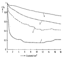
- the invention is illustrated by the figure.
- the figure shows characteristic curves of degradation of ZnS: Ag with different process parameters.
- the figure shows the relative intensity i / i o of the luminescence radiation measured at 4 keV electron energy as a function of the amount of charge applied per cm 2 of the phosphor surface.
- Characteristic curve 1 was obtained after no special measures to improve the degradation behavior were provided, i.e. with an evacuation in the room temperature range and without the introduction of a hydrolyzable gas.
- Characteristic curve 2 was measured after the evacuation was carried out at 350 ° C. and without the supply of a hydrolyzable gas.
Landscapes
- Engineering & Computer Science (AREA)
- Manufacturing & Machinery (AREA)
- Manufacture Of Electron Tubes, Discharge Lamp Vessels, Lead-In Wires, And The Like (AREA)
- Luminescent Compositions (AREA)
- Formation Of Various Coating Films On Cathode Ray Tubes And Lamps (AREA)
Description
- Die Erfindung bezieht sich auf ein Verfahren zur Herstellung einer Display-Röhre, welche im Innenraum eine zu stimulierter Emission anregbare Phosphorschicht aufweist, wobei der Innenraum mittels einer Vakuumpumpe evakuiert und danach gasdicht verschlossen wird.
- Solche Display-Röhren sind z.B. Feldemitterröhren (vgl. Information Display 5, 1989, Seiten 17 ff, oder I.E.E.E. Trans. E.D. 36,1989, Seiten 225 ff). Auch derartige Röhren müssen abschließend evakuiert werden (vgl. Valvo Berichte, 1974, Seite 77 ff).
- Die Stimulation der Emission kann auf beliebige Weise bewirkt werden, insbesondere durch Elektronenstrahlen. Es ist bekannt (Philips Tech. Rev. 1989, Seiten 335 ff), daS die Helligkeit des Lumineszenzlichts bei gegebener Intensität der Elektronenbestrahlung mit der Zeit in Abhängigkeit der Ladungsmenge des Elektronenbeschusses abnimmt (Degradation).
- Der Erfindung liegt die Aufgabe zugrunde, das Verfahren der eingangs genannten Art derart zu gestalten, daß die alterungsbedingte Degradation geringer wird.
- Die Lösung gelingt dadurch, daß vor und/oder während dem Evakuieren ein hydrolisierbares Gas während eines begrenzten Zeitintervalls in den Innenraum mit einem Partialdruck eingeleitet wird, welcher wesentlich größer als der zu ereichende End-Vakuumdruck der Kathodenstrahlröhre ist, daß danach die Evakuierung ohne weitere Gaszufuhr bis zum Erreichen des End-Vakuumdrucks fortgesetzt und dann die Kathodenstrahlröhre gasdicht verschlossen wird.
- Auf Phosphorkristallen angelagerte OH-Gruppen sind in wesentlichem Ausmaß für die Degradation verantwortlich, insbesondere dann, wenn zur Herstellung der Phosphatschicht silikathaltige Bindematerialien verwendet werden. Das erfindungsgemäß eingeleitete Gas wird durch Reaktion mit den OH-Ionen hydrolisiert. Im Falle von BCl₃ wird HCl abgespalten und beim Evakuieren abgesaugt.
- Ein nicht-oxidierendes Gas ist vorteilhaft, weil eine Oxidation der Phosphoroberfläche deren Lumineszenzwirkung beeinträchtigen würde. Ein besonders geeignetes Gas ist BCl₃. Dem Fachmann sind jedoch zahlreiche gleichwirkende Gase bekannt, insbesondere Halogenide, wie z. B. GeCl₄.
- Eine Verminderung der Degradation versuchte man bisher durch Erhitzen der Phosphorschicht auf etwa 350°C zu erreichen. Mit dem erfindungsgemäßen Verfahren erhält man jedoch wesentlich bessere Ergebnisse. Es hat sich dabei als vorteilhaft erwiesen, für das erfindungsgemäße Verfahren sehr viel niedrigere Erhitzungstemperaturen anzuwenden. Eine bevorzugte Lösung ist deshalb dadurch gekennzeichnet, daß die Evakuierung bei Temperaturen im Bereich von 50°C bis 250°C, insbesondere bei etwa 100°C, durchgeführt wird.
- Bei relativ niedrigen Elektronenenergien von bis zu 5 kev, wie sie bei flachen Kathodenstrahlröhren der eingangs genannten Art üblich sind, führt das Heizen der Phosphorschicht im Vakuum auf 350°C nicht zu einer ausreichenden Verminderung der Degradation, weil die Phosphoroberfläche bei hohen Temperaturen so verändert wird, daß eine höhere Empfindlichkeit gegen Elektronenbeschuß entsteht. Bei niedrigeren Temperaturen von etwa 100°C ist zwar die rein thermische Entfernung der OH-Gruppen von der Phosphoroberfläche sehr viel weniger wirksam. In Verbindung mit der erfindungsgemäßen Zufuhr eines hydrolosierbaren Gases resultiert jedoch eine Verminderung der Degradation in einem bisher nicht erreichten Ausmaß.
- Zur Verminderung der Degradation ist es ausreichend, daS der Partialdruck p des hydrolisierbaren Gases und die Zeit t von dessen Aufrechterhaltung derart gewählt sind, daß sich eine Flächenstoßrate der Moleküle des hydrolisierbaren Gases ergibt, welche mindestens den Wert hat, welcher sich bei Verwendung von BCl₃ und einem Produkt p·t = 0,8·10⁻³ mbar·min ergibt. Höhere Werte der Flächenstoßrate verbessern das Degradationsverhalten nicht mehr wesentlich.
- Die Erfindung ist für Feldemitterröhren besonders geeignet, da deren unbedeckte Phosphorschicht (ohne Aluminiumbedeckung) besonders gut mit dem hydrolisierbaren Gas kontaktiert. Die Erfindung ist jedoch auch für andere Arten von Display-Röhren geeignet, sofern deren Phosphorschichten mit dem hydrolisierbaren Gas kontaktierbar sind.
- Die Erfindung wird anhand der Figur näher erläutert.
- Die Figur zeigt Degradationskennlinien von ZnS:Ag bei verschiedenen Verfahrensparametern.
- In der Figur ist die relative Intensität i/io der bei 4 keV Elektronenenergie gemessenen Lumineszenzstrahlung in Abhängigkeit der je cm² der Phosphoroberfläche aufgebrachten Ladungsmenge dargestellt.
- Kennlinie 1 ergab sich, nachdem keine besonderen Maßnahmen zur Verbesserung des Degradationsverhaltens vorgesehen wurden, also bei einer Evakuierung im Bereich der Raumtemperatur und ohne Einleitung eines hydrolisierbaren Gases.
- Kennlinie 2 wurde gemessen, nachdem die Evakuierung bei 350°C und ohne Zufuhr eines hydrolisierbaren Gases durchgeführt wurde.
Claims (5)
- Verfahren zur Herstellung einer Display-Röhre, welche im Innenraum eine zu stimulierter Emission anregbare Phosphorschicht aufweist, wobei der Innenraum mittels einer Vakuumpumpe evakuiert und danach gasdicht verschlossen wird,
dadurch gekennzeichnet, daß vor und/oder während dem Evakuieren ein hydrolisierbares Gas während eines begrenzten Zeitintervalls in den Innenraum mit einem Partialdruck eingeleitet wird, welcher wesentlich größer als der zu erreichende End-Vakuumdruck der Kathodenstrahlröhre ist, daß danach die Evakuierung ohne weitere Gaszufuhr bis zum Erreichen des End-Vakuumdrucks fortgesetzt und dann die Kathodenstrahlröhre gasdicht verschlossen wird. - Verfahren nach Anspruch 1,
dadurch gekennzeichnet, daß das hydrolisierbare Gas nicht oxidierend ist. - Verfahren nach Anspruch 1 oder 2,
dadurch gekennzeichnet, daß das hydrolisierbare Gas BCl₃ ist. - Verfahren nach einem der Ansprüche 1 bis 3,
dadurch gekennzeichnet, daß die Evakuierung bei Temperaturen im Bereich von 50°C bis 250°C, insbesondere bei etwa 100°C, durchgeführt wird. - Verfahren nach einem der Ansprüche 1 bis 4,
dadurch gekennzeichnet, daß der Partialdruck (p) des hydrolisierbaren Gases und die Zeit (t) von dessen Aufrechterhaltung derart gewählt sind, daß sich eine Flächenstoßrate der Moleküle des hydrolisierbaren Gases ergibt, welche mindestens den Wert hat, welcher sich bei Verwendung von BCl₃ und einem Produkt p·t = 0,8·10⁻³ mbar·min ergibt.
Applications Claiming Priority (2)
| Application Number | Priority Date | Filing Date | Title |
|---|---|---|---|
| DE4223351A DE4223351A1 (de) | 1992-07-16 | 1992-07-16 | Verfahren zur Herstellung einer Kathodenstrahlröhre |
| DE4223351 | 1992-07-16 |
Publications (2)
| Publication Number | Publication Date |
|---|---|
| EP0580215A1 EP0580215A1 (de) | 1994-01-26 |
| EP0580215B1 true EP0580215B1 (de) | 1995-11-29 |
Family
ID=6463311
Family Applications (1)
| Application Number | Title | Priority Date | Filing Date |
|---|---|---|---|
| EP93202006A Expired - Lifetime EP0580215B1 (de) | 1992-07-16 | 1993-07-08 | Verfahren zur Herstellung einer Display-Röhre |
Country Status (4)
| Country | Link |
|---|---|
| US (1) | US5360361A (de) |
| EP (1) | EP0580215B1 (de) |
| JP (1) | JPH0821329B2 (de) |
| DE (2) | DE4223351A1 (de) |
Families Citing this family (4)
| Publication number | Priority date | Publication date | Assignee | Title |
|---|---|---|---|---|
| JPH08506854A (ja) * | 1993-12-17 | 1996-07-23 | フィリップス エレクトロニクス ネムローゼ フェンノートシャップ | 発光スクリーン |
| US5501928A (en) * | 1994-12-14 | 1996-03-26 | Thomson Consumer Electronics, Inc. | Method of manufacturing a luminescent screen for a CRT by conditioning a screen-structure layer |
| USD396501S (en) | 1997-09-18 | 1998-07-28 | Interlego Ag | Toy building element |
| DE102015207673A1 (de) | 2015-04-27 | 2016-10-27 | Wacker Chemie Ag | Verfahren zur Herstellung von Aminogruppen aufweisenden Organosiliciumverbindungen |
Family Cites Families (5)
| Publication number | Priority date | Publication date | Assignee | Title |
|---|---|---|---|---|
| US2871086A (en) * | 1956-02-10 | 1959-01-27 | Westinghouse Electric Corp | Method for baking and exhausting electron discharge devices |
| JPS58126639A (ja) * | 1982-01-20 | 1983-07-28 | Matsushita Electronics Corp | ハロゲン電球の製造方法 |
| JPS58126638A (ja) * | 1982-01-20 | 1983-07-28 | Matsushita Electronics Corp | ハロゲン電球の製造方法 |
| JPH0275129A (ja) * | 1988-09-09 | 1990-03-14 | Hitachi Ltd | カラー陰極線管の製造方法 |
| JPH0411688A (ja) * | 1990-04-27 | 1992-01-16 | Natl Inst For Res In Inorg Mater | Bn(c,h)からなる粒子線用螢光体 |
-
1992
- 1992-07-16 DE DE4223351A patent/DE4223351A1/de not_active Withdrawn
-
1993
- 1993-07-08 EP EP93202006A patent/EP0580215B1/de not_active Expired - Lifetime
- 1993-07-08 DE DE59301043T patent/DE59301043D1/de not_active Expired - Fee Related
- 1993-07-14 JP JP5174292A patent/JPH0821329B2/ja not_active Expired - Fee Related
- 1993-07-16 US US08/093,280 patent/US5360361A/en not_active Expired - Fee Related
Also Published As
| Publication number | Publication date |
|---|---|
| DE4223351A1 (de) | 1994-01-20 |
| JPH0821329B2 (ja) | 1996-03-04 |
| US5360361A (en) | 1994-11-01 |
| EP0580215A1 (de) | 1994-01-26 |
| JPH06162932A (ja) | 1994-06-10 |
| DE59301043D1 (de) | 1996-01-11 |
Similar Documents
| Publication | Publication Date | Title |
|---|---|---|
| DE69633311T2 (de) | Für Anzeigen von hoher Qualität geeignete Plasmaanzeigetafel und zugehöriges Herstellungsverfahren | |
| DE3789608T2 (de) | Reflektorschicht aus Aluminiumoxid für Leuchtstofflampen. | |
| DE2152418A1 (de) | Gasentladungsanzeige- und Speicherfeld mit Farbanzeige | |
| DE60310947T2 (de) | Vorrichtung zur erzeugung von strahlung | |
| DE69701926T2 (de) | Durch Niedrigspannungselektronenbestrahlung angeregte Vorrichtung mit erhöhter Helligkeit durch Reduzierung eines auf der Oberfläche eines Oxysulfidphosphors hergestellten Oxids | |
| DE3686186T2 (de) | Elektronenroehre. | |
| DE1646193A1 (de) | Beschichtungsverfahren | |
| DE10137015A1 (de) | Entladungsgefäß mit Excimerfüllung und zugehörige Entladungslampe | |
| EP0580215A1 (de) | Verfahren zur Herstellung einer Display-Röhre | |
| DE69019597T2 (de) | Niederdruckedelgasentladungslampe. | |
| DE2505991A1 (de) | Mit energiereichen strahlen anregbarer leuchtschirm | |
| DE2448801A1 (de) | Leuchtschirm fuer elektronenroehre | |
| DE602005005998T2 (de) | Prozess zur herstellung von plasma-displays mit verteiltem gettermaterial und so erhaltene displays | |
| DE2402244A1 (de) | Verfahren zur oberflaechenbehandlung von glas | |
| DE2819415C2 (de) | ||
| DE2937981A1 (de) | Leuchtstoff und diesen enthaltender, mit langsamen elektronen angeregter fluoreszenzbildschirm | |
| DE2646615A1 (de) | Verfahren zum anbringen einer leuchtstoffschicht auf einem glastraeger und deren verwendung | |
| DE1076270B (de) | Selbstleuchtende Leuchtstofflampe sowie Verfahren zu ihrer Herstellung | |
| DE1489409C (de) | Verfahren zum Bedecken der Innen wand einer Glühlampe mit einer Getter schicht | |
| DE2240338C3 (de) | Gasentladungsanzeige- und -speichervorrichtung | |
| DE891427C (de) | Verfahren zur Herstellung von Elektronen emittierenden Elektroden fuer elektrische Entladungsvorrichtungen | |
| DE2514543C3 (de) | Rot lumineszierendes Leuchtstoffpulver für Farbbildkathodenstrahlröhren | |
| DE4112858A1 (de) | Verfahren zur vorbehandlung eines pulverfoermigen leuchtstoffes | |
| DE1764903C3 (de) | Niederdruck -Cad miumdampf-Entladungslampe | |
| DE971227C (de) | Durchsichtiger Leuchtschirm fuer Kathodenstrahlroehren, insbesondere fuer Fernsehbildroehren, und Verfahren zur Herstellung eines solchen Leuchtschirmes |
Legal Events
| Date | Code | Title | Description |
|---|---|---|---|
| PUAI | Public reference made under article 153(3) epc to a published international application that has entered the european phase |
Free format text: ORIGINAL CODE: 0009012 |
|
| AK | Designated contracting states |
Kind code of ref document: A1 Designated state(s): DE ES FR GB IT |
|
| RAP1 | Party data changed (applicant data changed or rights of an application transferred) |
Owner name: N.V. PHILIPS' GLOEILAMPENFABRIEKEN Owner name: PHILIPS PATENTVERWALTUNG GMBH |
|
| 17P | Request for examination filed |
Effective date: 19940629 |
|
| 17Q | First examination report despatched |
Effective date: 19950126 |
|
| GRAA | (expected) grant |
Free format text: ORIGINAL CODE: 0009210 |
|
| AK | Designated contracting states |
Kind code of ref document: B1 Designated state(s): DE ES FR GB IT |
|
| PG25 | Lapsed in a contracting state [announced via postgrant information from national office to epo] |
Ref country code: ES Free format text: THE PATENT HAS BEEN ANNULLED BY A DECISION OF A NATIONAL AUTHORITY Effective date: 19951129 |
|
| REF | Corresponds to: |
Ref document number: 59301043 Country of ref document: DE Date of ref document: 19960111 |
|
| ITF | It: translation for a ep patent filed | ||
| GBT | Gb: translation of ep patent filed (gb section 77(6)(a)/1977) |
Effective date: 19960226 |
|
| ET | Fr: translation filed | ||
| PLBE | No opposition filed within time limit |
Free format text: ORIGINAL CODE: 0009261 |
|
| 26N | No opposition filed | ||
| REG | Reference to a national code |
Ref country code: FR Ref legal event code: CD |
|
| REG | Reference to a national code |
Ref country code: GB Ref legal event code: IF02 |
|
| REG | Reference to a national code |
Ref country code: FR Ref legal event code: D6 |
|
| REG | Reference to a national code |
Ref country code: GB Ref legal event code: 746 Effective date: 20021205 |
|
| PGFP | Annual fee paid to national office [announced via postgrant information from national office to epo] |
Ref country code: FR Payment date: 20040727 Year of fee payment: 12 |
|
| PGFP | Annual fee paid to national office [announced via postgrant information from national office to epo] |
Ref country code: GB Payment date: 20040729 Year of fee payment: 12 |
|
| PGFP | Annual fee paid to national office [announced via postgrant information from national office to epo] |
Ref country code: DE Payment date: 20040916 Year of fee payment: 12 |
|
| PG25 | Lapsed in a contracting state [announced via postgrant information from national office to epo] |
Ref country code: IT Free format text: LAPSE BECAUSE OF NON-PAYMENT OF DUE FEES;WARNING: LAPSES OF ITALIAN PATENTS WITH EFFECTIVE DATE BEFORE 2007 MAY HAVE OCCURRED AT ANY TIME BEFORE 2007. THE CORRECT EFFECTIVE DATE MAY BE DIFFERENT FROM THE ONE RECORDED. Effective date: 20050708 Ref country code: GB Free format text: LAPSE BECAUSE OF NON-PAYMENT OF DUE FEES Effective date: 20050708 |
|
| PG25 | Lapsed in a contracting state [announced via postgrant information from national office to epo] |
Ref country code: DE Free format text: LAPSE BECAUSE OF NON-PAYMENT OF DUE FEES Effective date: 20060201 |
|
| GBPC | Gb: european patent ceased through non-payment of renewal fee |
Effective date: 20050708 |
|
| PG25 | Lapsed in a contracting state [announced via postgrant information from national office to epo] |
Ref country code: FR Free format text: LAPSE BECAUSE OF NON-PAYMENT OF DUE FEES Effective date: 20060331 |
|
| REG | Reference to a national code |
Ref country code: FR Ref legal event code: ST Effective date: 20060331 |