EP0580809B1 - Systeme et procede de fabrication de stratifies en resine epoxy armee de fibres de verre et enrobee de cuivre - Google Patents
Systeme et procede de fabrication de stratifies en resine epoxy armee de fibres de verre et enrobee de cuivre Download PDFInfo
- Publication number
- EP0580809B1 EP0580809B1 EP92917422A EP92917422A EP0580809B1 EP 0580809 B1 EP0580809 B1 EP 0580809B1 EP 92917422 A EP92917422 A EP 92917422A EP 92917422 A EP92917422 A EP 92917422A EP 0580809 B1 EP0580809 B1 EP 0580809B1
- Authority
- EP
- European Patent Office
- Prior art keywords
- press plate
- clean room
- copper foil
- press
- plate
- Prior art date
- Legal status (The legal status is an assumption and is not a legal conclusion. Google has not performed a legal analysis and makes no representation as to the accuracy of the status listed.)
- Expired - Lifetime
Links
Images



Classifications
-
- B—PERFORMING OPERATIONS; TRANSPORTING
- B32—LAYERED PRODUCTS
- B32B—LAYERED PRODUCTS, i.e. PRODUCTS BUILT-UP OF STRATA OF FLAT OR NON-FLAT, e.g. CELLULAR OR HONEYCOMB, FORM
- B32B39/00—Layout of apparatus or plants, e.g. modular laminating systems
-
- B—PERFORMING OPERATIONS; TRANSPORTING
- B32—LAYERED PRODUCTS
- B32B—LAYERED PRODUCTS, i.e. PRODUCTS BUILT-UP OF STRATA OF FLAT OR NON-FLAT, e.g. CELLULAR OR HONEYCOMB, FORM
- B32B38/00—Ancillary operations in connection with laminating processes
- B32B38/18—Handling of layers or the laminate
- B32B38/1808—Handling of layers or the laminate characterised by the laying up of the layers
-
- H—ELECTRICITY
- H05—ELECTRIC TECHNIQUES NOT OTHERWISE PROVIDED FOR
- H05K—PRINTED CIRCUITS; CASINGS OR CONSTRUCTIONAL DETAILS OF ELECTRIC APPARATUS; MANUFACTURE OF ASSEMBLAGES OF ELECTRICAL COMPONENTS
- H05K3/00—Apparatus or processes for manufacturing printed circuits
- H05K3/02—Apparatus or processes for manufacturing printed circuits in which the conductive material is applied to the surface of the insulating support and is thereafter removed from such areas of the surface which are not intended for current conducting or shielding
- H05K3/022—Processes for manufacturing precursors of printed circuits, i.e. copper-clad substrates
-
- B—PERFORMING OPERATIONS; TRANSPORTING
- B32—LAYERED PRODUCTS
- B32B—LAYERED PRODUCTS, i.e. PRODUCTS BUILT-UP OF STRATA OF FLAT OR NON-FLAT, e.g. CELLULAR OR HONEYCOMB, FORM
- B32B2309/00—Parameters for the laminating or treatment process; Apparatus details
- B32B2309/60—In a particular environment
-
- B—PERFORMING OPERATIONS; TRANSPORTING
- B32—LAYERED PRODUCTS
- B32B—LAYERED PRODUCTS, i.e. PRODUCTS BUILT-UP OF STRATA OF FLAT OR NON-FLAT, e.g. CELLULAR OR HONEYCOMB, FORM
- B32B2309/00—Parameters for the laminating or treatment process; Apparatus details
- B32B2309/60—In a particular environment
- B32B2309/65—Dust free, e.g. clean room
-
- B—PERFORMING OPERATIONS; TRANSPORTING
- B32—LAYERED PRODUCTS
- B32B—LAYERED PRODUCTS, i.e. PRODUCTS BUILT-UP OF STRATA OF FLAT OR NON-FLAT, e.g. CELLULAR OR HONEYCOMB, FORM
- B32B2311/00—Metals, their alloys or their compounds
- B32B2311/12—Copper
-
- B—PERFORMING OPERATIONS; TRANSPORTING
- B32—LAYERED PRODUCTS
- B32B—LAYERED PRODUCTS, i.e. PRODUCTS BUILT-UP OF STRATA OF FLAT OR NON-FLAT, e.g. CELLULAR OR HONEYCOMB, FORM
- B32B2457/00—Electrical equipment
- B32B2457/08—PCBs, i.e. printed circuit boards
-
- B—PERFORMING OPERATIONS; TRANSPORTING
- B32—LAYERED PRODUCTS
- B32B—LAYERED PRODUCTS, i.e. PRODUCTS BUILT-UP OF STRATA OF FLAT OR NON-FLAT, e.g. CELLULAR OR HONEYCOMB, FORM
- B32B38/00—Ancillary operations in connection with laminating processes
- B32B38/16—Drying; Softening; Cleaning
- B32B38/162—Cleaning
-
- H—ELECTRICITY
- H05—ELECTRIC TECHNIQUES NOT OTHERWISE PROVIDED FOR
- H05K—PRINTED CIRCUITS; CASINGS OR CONSTRUCTIONAL DETAILS OF ELECTRIC APPARATUS; MANUFACTURE OF ASSEMBLAGES OF ELECTRICAL COMPONENTS
- H05K2203/00—Indexing scheme relating to apparatus or processes for manufacturing printed circuits covered by H05K3/00
- H05K2203/06—Lamination
- H05K2203/068—Features of the lamination press or of the lamination process, e.g. using special separator sheets
-
- Y—GENERAL TAGGING OF NEW TECHNOLOGICAL DEVELOPMENTS; GENERAL TAGGING OF CROSS-SECTIONAL TECHNOLOGIES SPANNING OVER SEVERAL SECTIONS OF THE IPC; TECHNICAL SUBJECTS COVERED BY FORMER USPC CROSS-REFERENCE ART COLLECTIONS [XRACs] AND DIGESTS
- Y10—TECHNICAL SUBJECTS COVERED BY FORMER USPC
- Y10T—TECHNICAL SUBJECTS COVERED BY FORMER US CLASSIFICATION
- Y10T156/00—Adhesive bonding and miscellaneous chemical manufacture
- Y10T156/10—Methods of surface bonding and/or assembly therefor
- Y10T156/1089—Methods of surface bonding and/or assembly therefor of discrete laminae to single face of additional lamina
- Y10T156/1092—All laminae planar and face to face
-
- Y—GENERAL TAGGING OF NEW TECHNOLOGICAL DEVELOPMENTS; GENERAL TAGGING OF CROSS-SECTIONAL TECHNOLOGIES SPANNING OVER SEVERAL SECTIONS OF THE IPC; TECHNICAL SUBJECTS COVERED BY FORMER USPC CROSS-REFERENCE ART COLLECTIONS [XRACs] AND DIGESTS
- Y10—TECHNICAL SUBJECTS COVERED BY FORMER USPC
- Y10T—TECHNICAL SUBJECTS COVERED BY FORMER US CLASSIFICATION
- Y10T156/00—Adhesive bonding and miscellaneous chemical manufacture
- Y10T156/17—Surface bonding means and/or assemblymeans with work feeding or handling means
- Y10T156/1702—For plural parts or plural areas of single part
- Y10T156/1744—Means bringing discrete articles into assembled relationship
-
- Y—GENERAL TAGGING OF NEW TECHNOLOGICAL DEVELOPMENTS; GENERAL TAGGING OF CROSS-SECTIONAL TECHNOLOGIES SPANNING OVER SEVERAL SECTIONS OF THE IPC; TECHNICAL SUBJECTS COVERED BY FORMER USPC CROSS-REFERENCE ART COLLECTIONS [XRACs] AND DIGESTS
- Y10—TECHNICAL SUBJECTS COVERED BY FORMER USPC
- Y10T—TECHNICAL SUBJECTS COVERED BY FORMER US CLASSIFICATION
- Y10T156/00—Adhesive bonding and miscellaneous chemical manufacture
- Y10T156/17—Surface bonding means and/or assemblymeans with work feeding or handling means
- Y10T156/1702—For plural parts or plural areas of single part
- Y10T156/1744—Means bringing discrete articles into assembled relationship
- Y10T156/1751—At least three articles
- Y10T156/1761—Stacked serially
Definitions
- the present invention relates generally to a method for manufacturing of flat laminate members and, more particularly, to the manufacturing of a copper clad laminate in the form of flat stock material used to fabricate printed circuit boards.
- a printed circuit board laminate generally comprises several sheets of epoxy impregnated fiberglass cloth, called "pre-preg", sandwiched on each side by a sheet of copper foil.
- a process for manufacturing a copper clad laminate commences with coating a web of glass cloth with a solution of epoxy resin to form a B-stage. The B-stage is sheeted to a suitable size, and a predetermined number of sheets are piled up to achieve a predetermined thickness of the final pre-preg laminate. Copper foil of suitable sheet size is then placed on each side of the B-stage pre-preg. The copper B-stage pre-preg copper laminate assembly is then placed between a pair of stainless steel press plates and inserted into a known vacuum hot press for pressing of the laminate.
- the assembly In the hot press, the assembly is heated up which causes the epoxy resin in the B-stage to melt and harden, forming the insulating core of the laminate. Subsequently, the laminate is cooled and removed with the press plates from the hot press. The laminate is then separated from the press plates which results in a final product while the press plates are reused for the next cycle of manufacturing laminates.
- a multiple assembly of press plates, copper foils and B-stage pre-pregs have to be prepared for insertion into the press.
- the multiple assembly known in the industry as a "book” may typically contain eight to twelve laminates.
- a “book” may comprise a carrier plate on which is stacked, in order, press pads, approximately twelve press plates each containing one laminate, one additional press plate, and press pads.
- the "carrier plate” is generally a hardened steel plate which carries the book of laminates from the laminate assembly point to the press area, then through breakdown of the book after pressing.
- the carrier plate is used to absorb the abuse caused during the material handling of the book.
- the thickness of the carrier plate is generally about 3 mm (0.118 inches).
- the length and width of the carrier plate is approximately 15.25 cm (six inches) larger in each direction than the largest press plate.
- T handles or tangs may be attached to each transverse end of the carrier for pulling the books on and off loading and unloading elevators.
- Each press plate is generally a stainless steel plate on which the laminate is assembled.
- the press plate length and width is generally the same as the pre-preg length and width.
- the copper foil length and width dimensions are generally 2.5 cm (one inch) larger in each direction than the press plate.
- the book of laminates is started by placing the first stainless steel press plate into a carrier plate/press pad base.
- the first or bottom copper foil is placed on the press plate, followed B-stage and the second or top copper foil.
- the process of placing the next press plate, bottom copper foil, B-stage, and top copper foil is repeated until the desired number of assemblies for the book is attained.
- the book is then removed for pressing and assembly of a new book starts.
- the process of building the book is typically performed in a "clean room", i.e., air entering the room is filtered.
- a clean room is preferred to minimize entry of particulate contaminants.
- the press plates are cleaned by mechanical means to minimize such contaminants.
- the largest problem for achieving defect-free surfaces comes from handling B-stage material in conjunction with the copper foil and stainless steel plates. This is because the B-stage contains very brittle epoxy resin and the resin particles and residues of glass fibers from pre-preg cutting and sheet surface abrasion is highly static and numerous. When handled in one room with clean surfaces of press plates and copper foils, either manually or with overhead handlers, some of these particles inevitably contact onto the critical surfaces and create surface defects.
- Such defects often require the laminate to be scrapped since various criteria for determining surface defects are stringent. For example, a dent of 0.38 mm (0.015 inches) in diameter appearing in the outer skin of the copper foil (top or bottom) would disqualify a laminate sheet as per military specification MIL-P-13949-G. Much more stringent requirements are also in place within the industry.
- a book of laminates reciprocates between two rooms. In one room, press plates and copper foils are handled and, in the second room, pre-preg is placed onto the copper foil underneath. This system tends to improve avoidance of contamination somewhat.
- the exposed surface of the B-stage has to enter the "metal" clean room and decelerate to a stop which creates slight air turbulence with further turbulence created when placing the top copper foil onto the exposed pre-preg.
- the movement of the buildup from room to room is slow and the large surface of the book and carriage tends to carry particulate contamination from room to room.
- the copper foils, B-stage pre-preg, press plates and carrier trays or plates are all located in the same room where the component assembly or layup is performed.
- a layup station has a central work surface such as a lift table or conveyor table that serves as the assembly point for the laminate components.
- a carrier plate Prior to commencement of the layup operation, a carrier plate is placed into position on the layup station's central work surface. Depending on the operation, the carrier plate may be placed manually or with automated conveyor equipment.
- the foils, B-stage and clean press plates are located around the work station so that they may be placed onto the carrier tray at appropriate intervals.
- stacks of properly sized foil, B-stage, and clean press plates are arranged around the carrier tray station so that minimum operator movement is required during the layup operation.
- foil and press plates are not stored around the layup station in stacks but are brought in in a continuous manner with overhead equipment as needed.
- the B-stage pre-preg is stacked near the central layup table.
- the kraft paper serves as a thermal lag material and also improves pressure distribution characteristics during lamination.
- Steps two through five are repeated until eight to twelve laminates have been stacked on top of the carrier tray. Sheets of kraft paper are placed on top of the last press plate. This then completes a "book", which is transported to a load elevator to await pressing, or lowered on a lift table to allow another carrier tray to be placed on top of it (most manual systems lay up an entire press load, 10-20 books, on a single lift table, and then transport the entire load to the press).
- the copper foil, B-stage, press plates, and carrier plates used in the shuttle layup system are not located in the same room as in the above-mentioned standard layup operation. Instead, the copper foil and press plates are located in one room while the B-stage is placed in an adjacent room. Stacks of properly sized foil, clean press plates, and B-stages are placed ergonomically in their respective rooms prior to commencement of the layup operation.
- a track or conveyor extends from the copper/plate room into the B-stage room through an opening in a common wall. The height of the conveyor or track is about 0.91 m (three feet) and is sized so that a carrier plate can be transferred back and forth (i.e. shuttled) between the two rooms.
- the carrier plate Prior to starting the layup process, the carrier plate is placed onto the shuttle conveyor in the copper/plate room. Kraft paper is placed onto the carrier plate to aid in pressure distribution and heat transfer adjustment, as aforesaid. After the carrier plate and kraft paper are in position, the layup process is as follow:
- Steps two through seven are repeated until the book is completed.
- Kraft paper is placed on the last press plate, and the book is taken to a load rack or elevator to await lamination under heat and pressure.
- Another object of the invention is to minimize the aforesaid particulate contamination of copper foils and press plate surfaces in a high speed continuous production process for the layup of one or more laminate books and the breakdown of such books, after curing, in an automated conveyorized system.
- Another object is to positively control the flow of air within the layup stations to prevent airborne resin and glass fiber particles from traveling to the copper foil/press plate rooms from a pre-preg layup room.
- Still another object is to achieve layup and breakdown of laminate books and minimize contamination of copper foil and press plate surfaces through the avoidance of overhead handling equipment and by means of minimal contact between conveyorized equipment and clean surfaces of the press plates during their conveyance in the layup process.
- the present invention provides a method for manufacturing copper-clad laminates each having a B-stage substrate sheet with at least one first sheet of copper foil adhering to at least one side of the B-stage substrate sheet.
- the method comprises introducing a press plate to a first layup region in a first clean room, applying a sheeted layer of copper foil to at least one surface of the press plate, transferring the resulting first sandwich of press plate and copper foil to a second layup region in a second clean room, through an opening in a common wall between said first and second clean rooms, forming a second sandwich of press plate, copper foil and B-stage substrate sheet in said second layup region, by applying a B-stage substrate sheet to the surface of the copper foil of said first sandwich, transferring said second sandwich to a stacking station downstream of said second clean room, and forming a book of second sandwiches sequentially stacked on a carrier plate as each is delivered from the second clean room, each second sandwich being separated from its adjacent second sandwich by a press plate.
- the ambient atmospheric air pressure within the first clean room is greater than the ambient atmospheric air pressure within the second clean room, to prevent the migration of B-stage dust or fibers from the second to the first clean room.
- additional copper foil is positioned on the B-stage in a third clean room located downstream from the second clean room.
- the ambient atmospheric air pressures within the first and third clean rooms are greater than the ambient atmospheric air pressure within the second clean room to prevent the migration of B-stage dust or fibers from the second to the first or third clean rooms.
- said first sandwich is formed on a layup table in the first clean room, by operating first means for disposing said copper foil on the layup table, by operating second means for positioning a press plate on said coper foil, by operating third means for positioning an additional copper foil on said press plate to form said first sandwich, and clamping the copper foil and press plate together via clamping contact with the longitudinally extending edges of the first sandwich.
- said layup table includes an air table adapted to receive the bottom copper foil, said air table including a plurality of air passageways substantially uniformly distributed in the upper surface of the air table, and means for supplying pressurized air through the passageways to establish a cushion of air between the table and lower surface of the bottom foil to prevent accumulation of B-stage dust or fibers on said lower surface.
- At least one book is conveyed from the stacking station to a pressing station, wherein heat and pressure is applied to said book to melt and then harden the B-stage laminates to adhere the copper foils to their associated B-stage; and subsequently to a breakdown station (B) where breakdown press plate handler means move between pickup and deposit positions to engage an uppermost exposed press plate within the book and transfer it to the deposit position; where it is received by press plate conveyor means which convey it to a first cleaning room, where cleaning means, positioned within the press plate conveyor means, clean the press plate before it is recycled to the first clean room, and the carrier plate, following removal of all the press plates from the book via the handler means, is conveyed to the stacking station for recycling.
- B breakdown station
- the B-stage substrate sheet and copper foil are handled and moved within the clean rooms without the use of overhead handling equipment.
- the system comprises a layup station including at least two clean rooms communicating with each other through an opening provided in an adjoining common wall area.
- the first clean room is adapted to contain copper foil and successively receive a plurality of press plates.
- the second clean room is adapted to contain the B-stage sheets.
- the first clean room has a first layup station on which is received one press plate with a sheeted layer of copper foil on at least one surface of the press plate.
- the resulting first sandwich including the press plate and sheeted copper foil layer is conveyed from the first clean room, through the opening, into the second clean room having a second layup region on which a sheet of B-stage is placed into contact with the first sandwich against the copper foil side thereof to form a second sandwich.
- a stacking station downstream from the second clean room, sequentially receives the second sandwiches to form a stacked book of sandwiched laminates separated from each other with a press plate.
- the book includes, and rests upon, a carrier plate delivered to the stacking station and on which the sandwiches are successively stacked.
- the at least one book is conveyed from the stacking station to a pressing station wherein heat and pressure is applied to the book to melt and then harden the B-stage laminates to adhere the copper foils to their associated B-stage.
- the at least one cured book is delivered from the pressing station to a breakdown station which includes a breakdown press plate handler movable between pickup and deposit positions for engaging an uppermost exposed press plate within the book and transferring it to the deposit position.
- a press plate conveyor receives the transferred press plates and conveys the same to the first clean room for recycling in the buildup of a subsequent book.
- a buffer is positioned within the press plate conveyor means for cleaning the press plate before it is conveyed to the first clean room.
- a carrier plate conveyor arrangement conveys the now exposed carrier plate to the stacking station for recycling.
- the relative ambient atmospheric air pressures within the first and second clean rooms are controlled to create an over-pressure preventing the migration of B-stage dust or fibers from the second to the first clean room through the opening.
- the atmospheric air pressure within the first clean room is therefore preferably greater than the atmospheric air pressure within the second clean room.
- a third clean room is provided downstream from the second clean room to contain additional copper foil.
- Means is provided for positioning copper foil in the first clean room onto a press plate to enable B-stage to be deposited on the copper foil in the second clean room. Further positioning means is provided to position the additional copper foil on the B-stage in the third clean room.
- the ambient atmospheric pressure in each of the first and third clean rooms is greater than the ambient pressure within the second clean room containing a B-stage to prevent migration of B-stage dust and fibers into either of these copper containing rooms.
- separate conveyors are provided in each of the clean rooms to avoid transfer of B-stage dust or fibers, via the conveyors, into the first and/or third clean rooms.
- the conveyors have minimal contact with the overlying press plate and therefore include a pair of thin belts positioned to contact and support only the longitudinally extending edges of the press plate and, optionally, a thin center belt adapted to contact the plate approximately along its central longitudinal axis.
- the center belt is preferably cleaned after about each revolution.
- the B-stage and copper foils are preferably handled and moved within the clean rooms without the use of overhead handling equipment.
- copper foil is disposed on the layup table in the first clean room and a press plate is positioned on the copper foil. Additional copper foil is placed on the press plate to form a metal sandwich.
- a clamping arrangement clamps the copper foils and press plate together via clamping contact with the longitudinally extending edges of the metal sandwich. The clamped metal sandwich is then conveyed into the second clean room and a sheet of B-stage is disposed against the surface of the top facing copper foil.
- the layup table preferably includes an air table adapted to receive the bottom cover foil.
- the air table includes plural air passageways substantially uniformly distributed throughout its table surface. Pressurized air is supplied through the passageways to establish an air cushion between the table and the air table is used to maintain contact between bottom copper and press plate, not to prevent contamination.
- the clamping arrangement preferably includes a pair of longitudinally extending stationary glide rails mounted adjacent the slides of the air table.
- a roller arrangement engages the respective glide rail in rolling contact for supporting the clamp for movement in the direction of conveyance of the metal sandwich.
- Each clamp is movable between an unclamped position and a clamping position in clamping contact only with the longitudinally extending edges of the sandwich exteding laterally outward from the table.
- the breakdown station preferably includes a book breakdown turntable rotatable through 90° between first and second angular orientations.
- a book transfer conveyor transfers the cured book from the pressing station to the breakdown turntable in the first orientation.
- the turntable then rotates into the second orientation to thereby locate the book in the pickup position of the breakdown press plate handler whereupon the press plates are sequentially removed from the book for discharge to the press plate conveyor.
- the breakdown turntable which is elevationally coextensive with the upstream end of the carrier plate conveyor, discharges the carrier plate to complete the disassembly of the cured book.
- the carrier plate is discharged directly onto an upstream end of the carrier plate conveyor arrangement which is located below the press plate conveyor.
- the carrier plate conveyor arrangement preferably includes a carrier plate indexing conveyor which receives the carrier plate from the upstream, lowers, and indexes the plate 90° while maintaining the same plate angluar orientation for travel in a direction of conveyance perpendicular to the direction of the press plate conveyor.
- the carrier plate is conveyed to a second carrier plate indexing conveyor positioned downstream from the first indexing conveyor.
- the second indexing conveyor lowers, indexes the plate 90° to convey the plate to a carrier plate turntable which is disposed beneath the layup line.
- This carrier plate conveyor conveys the carrier plate to a stacking turntable in the layup line which is adapted to receive the press plates with laminates in stacking arrangement to form a new book.
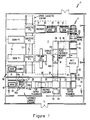
- FIG. 1 is a schematic plan view of a layup/breakdown system 10 of conveyors and handlers arranged to operate in conjunction with press loading and unloading equipment generally identified by reference numerals 12 and 14, respectively.
- the system 10 has a layup station L in which books 16 of partially cured laminates are formed and conveyed to a press room P where heat and pressure are applied to each book 16 to fully cure the laminates.
- the "pressed" books 16' of laminates are then conveyed through a series of conveyors and handlers at a breakdown station B where the books 16' are disassembled with the carrier plates 18 and press plates 20 returned to the layup station L for recycling in the assembly of new books 16 in a continuous process of breakdown and buildup.
- the following terms are intended to have the definitions noted below:
- each laminate 22 is built in three clean rooms, a bottom copper placement room 24, a B-stage placement room 26, and a top copper/stacking room 28.
- Narrow slots 30 are provided in the common walls 32 of adjacent clean rooms 24,26,28 to permit transfer of the press plate 20 to each clean room.
- Layup commences as a press plate 20 enters the bottom copper cleaning room 24 through an inlet opening 34 in one wall 36 thereof after exiting the press plate cleaning machine 38.
- the press plate 20 enters the clean room 24 on a conveyor 40 and is deposited onto an indexing conveyor 42 (at an upper elevational location coextensive with conveyor 40) located at the upstream-most end of the layup line L.
- the indexing conveyor 42 then lowers and indexes the press plate 20 through 90° while maintaining the same angular orientation.
- a stack 44 of sheeted bottom copper foil located above the indexing conveyor 42 allows the placement (either manually or by machine) of a sheet 45 of bottom copper onto the press plate 20 as the plate moves along a press plate conveyor unit 47.
- press plate/bottom copper 20,45 is then conveyed by press plate conveyor unit 47 (elevationally coextensive with the indexing conveyor in its lower elevational location) towards second clean room 26 as discussed infra.
- press plate conveyor unit 47 Elevationally coextensive with the indexing conveyor in its lower elevational location
- the indexing conveyor raises to await the next press plate 20.
- the press plate conveyor 47 conveys the press plate/bottom copper foil 20,45 from the first clean room 24 to second clean room 26 through elongate opening 30 in a common wall 32 therebetween.
- the elongate transverse opening 30 is aligned with the conveyor flow path and is of sufficient dimension to enable passage of the press plate/bottom copper foil 20,45 therethrough to prevent unnecessary air flow between the adjoining clean rooms 24,26.
- the press plate/bottom copper foil 20,45 is transferred to a second press plate conveyor 50 disposed in the second clean room 26 and aligned and elevationally coextensive with the first press plate conveyor 47 in the first clean room 24.
- the downstream and upstream ends 47a,50a of the first and second press plates conveyors 47,50 are disposed immediately adjacent the opening 30 within their respective clean rooms 24,26.
- pre-preg 52 is placed (manually or by machine) on the exposed upper surface of the bottom copper foil 45. To minimize contamination, pre-preg placement is the only operation that occurs in the second clean room 26. Thereafter, the press plate/bottom copper foil/pre-preg sandwich (20,45,52) is conveyed from the second clean room 26 to the third clean room 28 through an opening 30' provided in the adjoining common wall 32' therebetween. Immediately upon entering the third clean room 28 from the second clean room 26 through the opening 30', the leading end of the press plate/bottom copper/pre-preg sandwich (20,45,52) engages the upstream end of a third press plate conveyor 54 extending transversely and parallel to the opening 30'.
- top copper foil 55 is placed on the sandwich, either manually or by machine, to completely cover the exposed upper surface of the pre-preg 52.
- the top copper foil sheets 55 are disposed in a stack situated above the press plate conveyor 54 proximate the entrance opening.
- the laminate (45,52,55) comprising the top and bottom copper foils as well as the pre-preg may be manually laid up on top of the press plate 20.
- the press plate, with the laminate thereon is conveyed by the third press plate conveyor 54 to an automatic laminate stacking station 57 as depicted in Figures 1 and 2 where it is placed on top of a previous press plate/laminate package.
- the automatic laminate stacker includes a scissor lift or stacking turntable 59 incrementally movable between upper and lower positions.
- the turntable 59 initially receives a carrier plate 18 transferred to it via carrier plate conveyors 60 and 62 respectively located vertically below the press plate conveyors 50,54.
- the stacker rotates 90° and is then raised to a position slightly lower, e.g., 2.5 cm (one inch), than the elevation of the press plate conveyor 54 to accommodate sag in the middle of the laminate sandwich as it leaves conveyor 54.
- the sag occurs since the mechanism (not shown) which carries the laminate sandwich over the top of the stacker only holds the press plate by the edges parallel to the press plate conveyor with no center support, i.e., the center of the plate deflects.
- the turntable adjusts to a slightly lower position to make up for book thickness until the book 16 is built up to contain a required number of press plate/laminate packages.
- each mechanism includes a series of pins 59a,59b, respectively, mounted in bearings for rotation along horizontal axes.
- the pins 59a,59b may be approximately 9.5 mm (0.375 inches) in diameter and are located on 10.2 cm (four-inch) centers parallel to press plate conveyor 54.
- the mechanisms are located on each side of and above the scissor lift and are independent of the scissor lift.
- the pins 59a,59b protrude inward toward the center of the scissor lift a distance which only allows the pins to respectively carry the press plate coming off of conveyor 54 by the edges of the press plate parallel to conveyor 54.
- the pins touch the underside of the press plate preferably no more than 19 mm (3/4 of an inch) into the plate from the plate edge (i.e., the non-working area of the press plate).
- the pins 59a,59b are driven by synchronized boaters schematically depicted as 59c so that the surface speed of the rotating pins matches that of press plate conveyor 54.
- the rotating driven pin mechanisms on each side of the scissor lift 57 are capable of indexing movement in a direction transverse to the longitudinal direction of conveyance by an indexing distance of approximately 2.5 cm (one inch) to attain the following sequence of operation.
- the scissor lift or stacker 59 is located below the pin stacker mechanisms 59a,59b and is adjusted to a position slightly lower than the elevation of press plate conveyor 54 as aforesaid.
- the underside longitudinal edges of the press plate/laminate is engaged by the lead ones of pins 59a,59b and driven over the top of the scissor lift 59 by successive engagement with the downstream driven pin mechanisms 59a,59b located above and on each side of the scissor lift.
- the pin mechanisms 59a,59b which carry the laminate sandwich and press plate over the top of the scissor lift 59 only holds the press plate by the longitudinal edges parallel to the press plate conveyor with no center support. Therefore, the plate deflects or sags at the center which is the reason why the scissor lift adjusts to a position slightly lower than the press plate conveyor rather than at the same elevation, as aforesaid.
- the laminate sandwich is conveyored over the top of and in registration with the scissor lift by the driven pin mechanism 59a,59b.
- the driven pins 59a,59b then cease rotation so that the laminate sandwich stops at a predetermined position over the scissor lift.
- the scissor lift then adjusts automatically upward until the center of the deflected pres plate laminate sandwich touches the laminate previously stacked on the scissor lift.
- the driven pin mechanisms on each side of the scissor lift then index outward away from the center of the scissor lift and by approximately 2.5 cm (one inch) to thereby release the longitudinal edges of the press plate laminate package to deposit and stack it on top of the previous laminate package.
- the carrier plates 18 are sequentially conveyed into second clean room 26 from breakdown station B along a series of carrier plate conveyors and through an opening 34' in wall 36' to be deposited on a turntable 64 elevationally coextensive and upstream from carrier plate conveyor 60.
- the carrier plate 18 is rotated 90° on the turntable 64 before being deposited onto carrier plate conveyor 60 so that the lengthwise edges of the carrier plate are parallel to the direction of conveyance for ease of transfer to the stacking turntable 59 beneath the press plate conveyors 50,54.
- the stacker After being deposited onto stacker 59, the stacker again rotates the carrier plate through 90° so that it assumes the same orientation as the press plate/laminate packages.
- the book 16 is transferred to a book indexing conveyor 66 which receives the book from the stacker 59, lowers, indexes the book 90° and discharges it onto an elevator delivery conveyor 68 ( Figure 1) while maintaining the same plate orientation.
- the elevator delivery conveyor 68 which extends across the loading elevator platform, delivers the book onto the elevator/loader 12.
- the elevator/loader 12 rises and lifts the book off the elevator delivery conveyor to load same into movable cassettes 70 with the loader.
- cassettes 70 move along rails 72 and are transferred via booms 74 into a vacuum hot press 76 within the press room P and then a cage unloading elevator 14 having a puller device adapted to engage the plate tang of the carrier plate to pull the cured book 16' onto an elevator discharge conveyor 80.
- a vacuum hot press 76 such as may be used in the present invention comprises 21 heated plates, called platens, spaced apart vertically by approximately 15 cm (six inches). This yields 20 opening between the plates.
- the number of plates and spacing varies with different presses.
- Each plate is heated using high pressure hot water, steam, electric, or oil and the like.
- Around the platens is a structural box with doors which, with the doors closed, can be evacuated.
- the books 16 of laminates are inserted into the spaces (openings) between the platens. The doors are then closed and the press evacuated. Below the bottom platen is large ram inside of a hydraulic cylinder.
- Hydraulic pressure is applied to the underside of the cylinder to raise the ram which then raises the bottom platen with the book on top of it. As it is being raised, the bottom platen with the book contacts the second platen with the book, and pushes it up to contact the next platen until all 21 platens are squeezed together with the laminate books between them. Under tightly controlled temperatures and pressures, the books 16 are heated up and the epoxy resin in the B-stage melts and hardens. The books 16' are cooled in this press or automatically transferred to another press for cooling.
- a representative vacuum hot press 76 that may be used in the present invention is manufactured by Technical Machine Products, 5500 Walworth Ave., Cleveland, Ohio under Model No. 20204/Hot Press.
- the cassettes 70 are devices used for staging and transferring of a press load of books. Each cassette 70 comprises the same number of tiers as there are openings in the presses 76 or 78. When the cassettes 70, which travel on rails 72 between designated points, are respectively stationed in front of a press 76 or 78, the complete set of books can be slid horizontally across into and out of the press at one time in a known manner.
- a representative cassette structure 70 is available from Technical Machine Products, 5500 Walworth Ave., Cleveland, Ohio under Model No. 20204/Cassette.
- the booms 74 are mechanisms which transfer a complete press load of books simultaneously to, and from, one of presses 76 or 78 from, respectively into into the associated, aligned cassette 70.
- Such a boom 74 as used in the present invention is available from Technical Machine Products, 5500 Walworth Ave., Cleveland, Ohio under Model No. 20204/Boom.
- the loader 12 is essentially an elevator conveyor which accepts one book at a time from the elevator delivery conveyor 68.
- the elevator conveyor or loader 12 travels vertically in front of the cassette 70 and inserts the books sequentially onto each tier of the cassette until the cassette is full.
- the cassette 70 then travels along rails 72 in front of the press 76 or 78 at which time the boom 74 pushes the load of books into the press openings.
- a loader or elevator conveyor 12 that may be used in the present invention is available from Technical Machine Products, 5500 Walworth Ave., Cleveland, Ohio under Model No. 20204/Loader & 20204/Unloader.
- Unloader 14 is similar to loader 12. After the books have been pressed, the boom 74 pulls the load of books out of the press onto one of cassettes 70. The cassette 70 travels to a position in front of the unloader 12 where the elevator/conveyor pulls the books out of the cassette one at a time for discharge onto elevator discharge conveyor 80.
- a book transfer conveyor 82 receives the book from the elevator discharge conveyor 80 and then discharges the book onto a book breakdown turntable 84 depicted in Figures 1 and 3.
- the book breakdown turntable 84 initially rotates the book 90° into a pickup position where the book is disassembled with a breakdown press plate handler 85.
- the handler 85 is movable between the pickup and deposit positions to sequentially engage the topmost exposed press plates 20 via a handler suction cup frame 87, described in more detail below, that delivers the transferred press plates onto a press plate conveyor 90.
- the thusly transferred press plate is conveyed via downstream press plate conveyors 90 to a plate cleaner 38 which subsequently transfers the clean press plate to the press plate indexing conveyor 40 which feeds the clean press plate back to the first clean room 24 in a new book building process in a continuous manner.
- the press plate cleaner or wet buffer 38 is a conventional piece of equipment such as Model No. 8870-210.00 manufactured by Wasero Mashinenbau GmbH, D-4322 Sprockhovel 1, West Germany.
- the cleaner 38 generally comprises a washing section which sprays water onto the top and bottom of the press plate 20 as rotary abrasive brushes scrub both sides of the plate as it travels continuously on conveyor 90.
- the plate 20 then enters a rinsing section where water is again sprayed onto both top and bottom sides thereof before it is conveyed into a drying section where hot air is blown onto the plate through air knives to dry the plate before it exits the cleaner 38. Thereafter, the plate re-enters bottom copper placement room 24 on conveyor 40 through opening 34 in wall 36.
- the book breakdown turntable 84 which is lowered elevationally coextensive with the upstream end of a carrier plate conveyor 92 located beneath the press plate conveyor 90, discharges the empty carrier plate 18 onto conveyor 92 for conveyance to a carrier plate indexing conveyor 94.
- the indexing conveyor 94 lowers, indexes the plate 90° and discharges it onto another carrier plate conveyor 96 maintaining the same plate orientation.
- This carrier plate conveyor 96 has a direction of travel perpendicular to the direction of conveyance of the press plate conveyors 90.
- This carrier plate conveyor 96 discharges the plate onto a second carrier plate indexing conveyor 98 which lowers and indexes the plate 90° in the direction of the layup station L while maintaining the same plate orientation.
- the plate 18 is then received on additional carrier plate conveyors 100 for discharge onto the carrier plate turntable 64 disposed beneath the layup line.
- the turntable 64 rotates the plate 90° so that it has the same angular orientation as the press plate/laminate package being formed above it.
- the carrier plate 18 is conveyed via carrier plate conveyors 60,62 for discharge onto the automatic laminate stacking table 59 in the manner described above.
- HVAC system Conventional
- over-pressure in the top and bottom copper placement rooms 24,28 in relationship to the B-stage room 26, such over-pressure preferably being on the order of 25 Pa (0.10 inches of water).
- This over-pressure feature prevents pre-preg dust from entering either bottom or copper placement room 24 or 28 through openings 30,30' in walls 32,32', respectively.
- Figure 5A is a conceptual sketch of a press plate conveyor top utilizing three belts 100 for carrying a press plate, one belt supporting each longitudinal side edge of press plate 20 and one center belt 100a supporting the middle underside of the press plate.
- a belt cleaner (not shown) may be installed on the underside of the conveyor for continuous cleaning of the belts.
- the two edge belts 100 should contact the underside of the plate side no further into the plate than 2.5 cm (one inch) from the edge. Such contact is highly preferred in an effort to further reduce the possibility of contamination from the belt transferring contaminant onto the plate and thus the laminate.
- the 2.5 cm (one inch) edge of the laminate is trimmed off and scrapped and, therefore, it is not as critical if contamination is present in this 2.5 cm (one inch) edge.
- the belt should preferably be easily removable for end of shift cleaning of the entire system as well as changeover for different plate sizes.
- the belts 100 are preferably formed of a carbon-filled conductive material.
- the material is grounded to prevent a buildup of static charge on the press plates and thus attract any contaminant which may be present in the area.
- the center belt is preferably cleaned using a rotating brush which is continuously cleaned by a vacuum system.
- FIG. 5 is an illustration of a preferred embodiment of a press plate conveyor (40,42,47,50,54) wherein center belt 100a is disposed within a roller 102 secured to a shaft 104 suitably mounted in bearings 105 for rotation in a known manner.
- the center belt 100a projects upwardly from a mirror finished shield 106.
- a pair of stationary side rails 108 respectively support side belts or guides 100 (preferably made of a frictionless material such as Teflon) in approximately the same elevational plane as belt 100a against which guides and belt the underside of press plate 20 is supported.
- a pair of coaxial slide shafts 110 project inwardly from side rails 108 into opposite open ends of shaft 104.
- Lower slide or guide shafts 112 also extend inwardly from side rails 108 to support a pair of lower longitudinally extending rails 114 supporting the center shaft 104 and thereby the center belt structure 100a.
- the lateral spacing between side rails 108 may be adjusted to accommodate press plates 20 of different width, simply by manually moving the side rails 108 in relation to each other, causing sliding movement of shafts 110,112 within center shaft 104 or support collars 116 secured to lower support rails 114.
- breakdown press plate handler 85 utilizes a suction cup frame 87 having three sets of pairs of suction cups 120 (connected to a vacuum system not shown) to lift the press plates 20 from breakdown table 84 for placement on upstreammost press plate conveyor 90 (Figure 3).
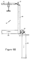
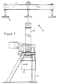
- Figures 6-7 are illustrations of one embodiment of press plate handler 85.
- press plate handler 85 comprises a pair of upright supports 121 ( Figure 6) and 123 ( Figure 7) respectively located outwardly adjacent the sides of press plate conveyor 90 between the press plate conveyor and breakdown turntable 84.
- a support shaft 125 extends between supports 121,123 and is rotatably journalled to these supports as at 127.
- the suction cup frame 87 comprises a pair of vertical support members 128 keyed at their lower ends to an enlarged diameter portion 129 of the support shaft; counterweights 130 ( Figures 6A and 7) are secured to the lower end of the lefthand support 128.
- a pair of brackets (e.g., L-brackets) 132 are respectively secured approximately at their mid-sections to the uppermost ends of vertical supports 128 as best depicted in Figures 6A, 6B and 7.
- Three support shafts 134 extend between and are rotatably secured to the brackets 132 with bearings 135.
- An outer shaft 137 is rotatably mounted to each shaft 134.
- a pair of press plate suction cup assemblies 139 are secured to the outer shaft 137 and are adapted to be connected to a source of suction with lines 140.
- the suction cup assemblies 139 interconnected to their respective shafts 134 extend in a common plane which is maintained in a horizontal manner by means of chain drive mechanism 145.
- Chain drive mechanism 145 essentially acts as a timing chain enabling the frame defined by bracket rails 132 and shafts 134 to remain in a horizontal plane as uprights 128 rotate about center support shaft 129 from the three o'clock position of Figure 3 counter-clockwise to the nine o'clock position to deposit an uppermost exposed press plate 20 on breakdown turntable 84 to upstreammost press plate conveyor 90.
- each press plate 20 is removed from turntable 84 with handler 85, the cured laminate is removed, either manually or by machine, to thereby expose the next press plate for removal with the handler in the breakdown procedure.
- Figures 8 and 9 are illustrations of a second embodiment of a layup line that may be used in place of clean rooms 24,26,28 in the Figure 1 embodiment but otherwise in conjunction with the remainder of the Figure 1 embodiment.
- clean press plates (such as supplied by conveyor 40 from wet buffer 38) enter a clean room wherein a copper foil 130 is placed on an upward exposed surface of an air table 132 either manually or by means of an automatic dispenser (not shown).
- a clean press plate 20 is then placed on the upper surface of foil or copper sheet 130 and another clean foil or copper sheet 134 is then placed on the upper surface of press plate 20.
- a clamping mechanism 135 then pivots to clamp the edges of metal foils 130 and 134 to the edges of press plate 20.
- Air is then turned on and the air table 132 is lowered.
- the clamping mechanisms 135 which are on movable rails 137 supported on glide tracks 140 are then moved through a slot 30 ( Figure 2) into a pre-preg room where the copper, plate, copper sandwich is stacked on a carrier plate 18 and the clamp is released. B-stage pre-preg is then placed on the top copper 134.
- the clamping mechanisms/slide rail assembly 135,137 return to the first clean room to pickup another copper, plate, copper sandwich. This process is repeated until the desired number of laminates are stacked on the carrier plate.
- Laminate stacking turntable 59 such as depicted in Figure 2 may be utilized in this second embodiment.
- Air table 132 The purpose of air table 132 is to maintain the bottom metal foil 130 in intimate contact with the press plate 20 to prevent foreign material from entering this interface. Obviously, this foil 130 becomes the top copper foil of a laminate and it is important that the upper surface of this foil 130 (i.e., in contact with the bottom surface of press plate 20) be kept free from foreign material.
- Air table 130 in accordance with one embodiment, has 403 81.3 cm (32-inch) holes uniformly distributed throughout its surface which enables approximately 28.3 m3/min (1000 c.f.m.) of air to pass through these holes.
- the air table may be made from 12.7 mm (half-inch) Teflon and the aforementioned air flow is capable of floating the press plate/foil sandwich on the table.
- the air table may rest upon a base 142 extending between stationary longitudinally extending support frames 144.
- a mechanism for raising and lowering air table 132 is not shown but nonetheless obvious to one of ordinary skill in the art based upon the foregoing description.
- the movable slide rails 137 support vertically spaced roller wheels 140a engaging top and bottom surfaces of stationary guide rails 140. These stationary guide rails 140 are suitably bolted to support frames 144 as at 146.
- FIG 10 is a schematic view of a third embodiment of this invention wherein four conveyors 150, 152, 154 and 156 are provided within a pair of clean rooms 158 and 160 downstream from buffer 38.
- upstreammost conveyor 150 receives a clean press plate 20 from buffer 38 through an opening 34.
- Conveyor 152 serves as a staging conveyor to separate successive plates 20 a predetermined distance, e.g. 2.5 cm (one inch) from one another.
- Conveyor 154 unwinds copper foil 162 from a roll 164 beneath the conveyor with the press plates 20 being fed from the second conveyor 152 onto the top of the copper foil 162 covering the upper run of conveyor 154.
- Another roll 166 of copper foil feeds a second layer of copper 168 onto the top of the press plate 20 on conveyor 154.
- the copper foil 168 is fed from between a pair of tensioning rollers 170 to a holddown 172 located above an upstream portion of conveyor 154. Thereby, as the press plate exits clean room 158 through opening 170 in wall 172, it is covered on both sides with top and bottom foils 168,162, respectively.
- An air table 174 (having a structure similar to air table 132 in the Figure 9 embodiment) is disposed in second clean room 160 between conveyors 154 and 156.
- a transversely extending notch 176 adapted to receive an overhead cutting member 180 which is arranged to cut through the strips 162,168 in the space between successively conveyed press plates 20.
- a foil/press plate/foil sandwich similar to the sandwiches formed in the second embodiment is transferred onto a scissors lift 180 from conveyor 156. As each sandwich is transferred to the scissors lift, a sheet of pre-preg is manually or otherwise placed on the sandwich on the scissors lift to form a stack of laminates thereon.
- a movable clamping mechanism of the type disclosed in Figure 8 and 9 may be utilized to transfer the sandwich from downstream conveyor 156 to the scissors lift 180.
- a book is completed on the scissors lift 180 it is transferred to a conveyor 66 (such as in the Figure 1 embodiment) for ultimate conveyance to a press room P in the manner described above.
Landscapes
- Engineering & Computer Science (AREA)
- Manufacturing & Machinery (AREA)
- Microelectronics & Electronic Packaging (AREA)
- Casting Or Compression Moulding Of Plastics Or The Like (AREA)
- Laminated Bodies (AREA)
- Reinforced Plastic Materials (AREA)
Claims (9)
- Procédé de fabrication de stratifiés (22) plaqués de cuivre, chaque stratifié possédant une feuille de substrat à l'état "B" (52) avec au moins une première feuille de clinquant de cuivre (45) adhérant au moins à un côté de la feuille de substrat à l'état "B" (52), procédé qui comprend l'introduction d'un plateau de presse (20) jusqu'à une première zone de superposition de couches dans une première salle blanche (24), l'application d'une couche en feuille de clinquant de cuivre (45) sur au moins une surface du plateau de presse, le transfert du premier sandwich résultant du plateau de presse et du clinquant de cuivre jusqu'à une seconde zone de superposition de couches dans une deuxième salle blanche (26), par une ouverture (30) prévue dans une paroi commune (32) entre lesdites première et deuxième salles blanches, la formation d'un deuxième sandwich de plateau de presse, clinquant de cuivre et feuille de substrat à l'état "B" dans ladite seconde zone de superposition de couches, en appliquant une feuille de substrat à l'état "B" (52) sur la surface du clinquant de cuivre dudit premier sandwich, le transfert du deuxième sandwich vers un poste d'empilage (57) en aval de ladite deuxième salle blanche, et la formation d'un livre (16) de deuxièmes sandwiches séquentiellement empilés sur un plateau de support (18) lorsque chaque deuxième sandwich est délivré de la deuxième salle blanche, chaque deuxième sandwich étant séparé de son deuxième sandwich adjacent par un plateau de presse (20).
- Procédé suivant la revendication 1, caractérisé en ce que la pression atmosphérique régnant dans la première salle blanche (24) est supérieure à la pression atmosphérique régnant dans la deuxième salle blanche (26), afin d'empêcher que des poussières ou fibres à l'état "B" migrent depuis la deuxième vers la première salle blanche.
- Procédé suivant la revendication 1 ou 2, caractérisé en ce qu'une feuille de clinquant de cuivre supplémentaire est placée sur la feuille de substrat à l'état "B" dans une troisième salle blanche (28) située en aval de la deuxième salle blanche (26).
- Procédé suivant la revendication 3, caractérisé en ce que les pressions atmosphériques régnant dans les première et troisième salles blanches (24, 28) sont supérieures à la pression atmosphérique régnant dans la deuxième salle blanche (26) afin d'empêcher que des poussières ou fibres à l'état "B" migrent depuis la deuxième vers la première ou troisième salle blanche.
- Procédé suivant l'une quelconque des revendications 1 à 4, caractérisé en ce que des transporteurs séparés (40, 42, 47, 50, 54) sont prévus dans chaque salle blanche afin d'éviter le transfert de poussières ou fibres à l'état "B", via les transporteurs, dans la première ou troisième salle blanche.
- Procédé suivant l'une quelconque des revendications 1 à 5, caractérisé en ce que ledit premier sandwich est formé sur une table de superposition de couches dans la première salle blanche (24), en actionnant un premier moyen afin de disposer ladite feuille de clinquant de cuivre (45) sur la table de superposition de couches, en actionnant un deuxième moyen afin de placer un plateau de presse (20) sur ladite feuille de clinquant de cuivre, en actionnant un troisième moyen afin de placer une feuille de clinquant de cuivre supplémentaire sur ledit plateau de presse en vue de former ledit premier sandwich, et en fixant les feuilles de clinquant de cuivre et le plateau de presse ensemble par un contact de serrage avec les bords s'étendant longitudinalement du premier sandwich.
- Procédé suivant la revendication 6, caractérisé en ce que ladite table de superposition de couches comprend une table à coussin d'air (132, 174) à même de recevoir la feuille de clinquant de cuivre inférieure, ladite table à coussin d'air comprenant une pluralité de conduits d'air distribués sensiblement de manière uniforme dans la surface supérieure de la table à coussin d'air, et des moyens destinés à fournir de l'air comprimé par les conduits afin d'établir un coussin d'air entre la table et la surface inférieure de la feuille de clinquant inférieure, de manière à empêcher l'accumulation de poussières ou fibres à l'état "B" sur ladite surface inférieure.
- Procédé suivant l'une quelconque des revendications 1 à 7, caractérisé en ce qu'au moins un livre (16) est transporté du poste d'empilage (57) jusqu'à un poste de pressage (76), dans lequel on chauffe et on comprime ledit livre afin de faire fondre et ensuite durcir les feuilles de substrat ou stratifiés à l'état "B" de manière à faire adhérer les feuilles de clinquant de cuivre à leurs feuilles de substrat à l'état "B" associées, et ensuite jusqu'à un poste de désassemblage (B) où des moyens de manutention de plateaux de presse de désassemblage (85) se déplacent entre des positions de préhension et de dépôt afin d'attaquer un plateau de presse exposé supérieur dans le livre et de le transférer vers la position de dépôt où il est reçu par des moyens de transport (90) de plateaux de presse qui le transportent jusqu'à une première salle de nettoyage, où des moyens de nettoyage (38), placés dans les moyens de transport (90) de plateaux de presse, nettoient le plateau de presse avant de le transporter vers la première salle blanche (24), et le plateau de support, après l'enlèvement de tous les plateaux de presse du livre via les moyens de manutention (85), est transporté jusqu'au poste d'empilage pour recyclage.
- Procédé suivant l'une quelconque des revendications 1 à 8, caractérisé en ce que la feuille de substrat à l'état "B" (52) et la feuille de clinquant de cuivre (45) sont manipulées et déplacées dans les salles blanches (24, 26, 28) sans utiliser des équipements de manutention aériens.
Applications Claiming Priority (3)
| Application Number | Priority Date | Filing Date | Title |
|---|---|---|---|
| US685337 | 1991-04-15 | ||
| US07/685,337 US5160567A (en) | 1991-04-15 | 1991-04-15 | System and method for manufacturing copper clad glass epoxy laminates |
| PCT/US1992/002149 WO1992018334A1 (fr) | 1991-04-15 | 1992-03-18 | Systeme et procede de fabrication de stratifies en resine epoxy armee de fibres de verre et enrobee de cuivre |
Publications (2)
| Publication Number | Publication Date |
|---|---|
| EP0580809A1 EP0580809A1 (fr) | 1994-02-02 |
| EP0580809B1 true EP0580809B1 (fr) | 1996-01-03 |
Family
ID=24751755
Family Applications (1)
| Application Number | Title | Priority Date | Filing Date |
|---|---|---|---|
| EP92917422A Expired - Lifetime EP0580809B1 (fr) | 1991-04-15 | 1992-03-18 | Systeme et procede de fabrication de stratifies en resine epoxy armee de fibres de verre et enrobee de cuivre |
Country Status (7)
| Country | Link |
|---|---|
| US (1) | US5160567A (fr) |
| EP (1) | EP0580809B1 (fr) |
| JP (1) | JP3001259B2 (fr) |
| AT (1) | ATE132432T1 (fr) |
| CZ (1) | CZ218793A3 (fr) |
| DE (1) | DE69207396T2 (fr) |
| WO (1) | WO1992018334A1 (fr) |
Cited By (1)
| Publication number | Priority date | Publication date | Assignee | Title |
|---|---|---|---|---|
| DE19731133A1 (de) * | 1997-07-19 | 1999-01-21 | Siempelkamp Gmbh & Co | Verfahren zum Herstellen von Laminaten, insbesondere von Industrielaminaten |
Families Citing this family (18)
| Publication number | Priority date | Publication date | Assignee | Title |
|---|---|---|---|---|
| IT1271941B (it) * | 1993-02-10 | 1997-06-10 | Cedal Srl | Procedimento per la produzione di laminati plastici con lamine metalliche in specie per circuiti stampanti, con riscaldamento endotermico. |
| TW346443B (en) * | 1995-11-02 | 1998-12-01 | Toyo Koban Kk | Method and apparatus for production of laminated metal sheet |
| US5987736A (en) * | 1996-03-01 | 1999-11-23 | Copp; John B. | Printed circuit board fabrication apparatus |
| DE19731538C2 (de) * | 1997-07-23 | 1999-07-22 | Siempelkamp Gmbh & Co | Anlage zum Herstellen von Laminaten, insbesondere von Industrielaminaten |
| DE19831461C1 (de) * | 1998-07-14 | 2000-02-24 | Dieter Backhaus | Verfahren zur partiellen Verbindung von Kupferfolien und Trennblechen (CuAI-Verfahren) |
| IT1305116B1 (it) * | 1998-09-14 | 2001-04-10 | Zincocelere Spa | Componente per circuito stampato multistrato, metodo per la suafabbricazione e relativo circuito stampato multiuso. |
| DE19859613C2 (de) * | 1998-12-23 | 2001-09-06 | Buerkle Gmbh Robert | Presspaketaufbau und Verfahren zu dessen Herstellung |
| US6584820B1 (en) | 1999-09-23 | 2003-07-01 | Polyclad Laminates, Inc. | Surface enhanced metal press plates for use in manufacture of laminates and multilayer materials and method of making same |
| US6955740B2 (en) | 2002-01-10 | 2005-10-18 | Polyclad Laminates, Inc. | Production of laminates for printed wiring boards using protective carrier |
| US20040253473A1 (en) * | 2003-06-13 | 2004-12-16 | Michael Weekes | Metal foil composite structure for producing clad laminate |
| JP4297163B2 (ja) * | 2004-10-08 | 2009-07-15 | パナソニック株式会社 | 多層回路基板の製造方法 |
| WO2008152737A1 (fr) * | 2007-06-15 | 2008-12-18 | Kitagawa Seiki Kabushiki Kaisha | Appareil de pression de formage de substrat et procédé de pression de formage de substrat |
| CN103552351B (zh) * | 2013-11-04 | 2016-03-16 | 昆山美连德电子科技有限公司 | 一种贴铜箔机 |
| MY192520A (en) * | 2014-07-10 | 2022-08-25 | Isola Usa Corp | Thin resin films and their use in layups |
| AU2020221056B2 (en) | 2019-02-14 | 2024-02-08 | Boxabl Inc | Foldable building structures with utility channels and laminate enclosures |
| WO2022154926A1 (fr) * | 2021-01-12 | 2022-07-21 | Build Ip Llc | Installation de fabrication d'élément d'enveloppe |
| US11718984B2 (en) | 2021-01-12 | 2023-08-08 | Build Ip Llc | Liftable foldable transportable buildings |
| US11739547B2 (en) | 2021-01-12 | 2023-08-29 | Build Ip Llc | Stackable foldable transportable buildings |
Family Cites Families (30)
| Publication number | Priority date | Publication date | Assignee | Title |
|---|---|---|---|---|
| US2186954A (en) * | 1935-10-29 | 1940-01-16 | New England Mica Company | Art of manufacturing high temperature mica products |
| US3215579A (en) * | 1963-01-23 | 1965-11-02 | Formica Corp | Process for releasing laminates |
| US3573126A (en) * | 1968-06-07 | 1971-03-30 | Gti Corp | Methods of manufacturing electrical circuits |
| US3617613A (en) * | 1968-10-17 | 1971-11-02 | Spaulding Fibre Co | Punchable printed circuit board base |
| JPS5222380B2 (fr) * | 1973-05-30 | 1977-06-17 | ||
| US3969177A (en) * | 1974-06-24 | 1976-07-13 | International Business Machines Corporation | Laminating method |
| US4207129A (en) * | 1977-11-21 | 1980-06-10 | Uop Inc. | Manufacture of conductive or semi-conductive elements by means of a continuous pultrusion process |
| US4249977A (en) * | 1979-07-17 | 1981-02-10 | General Electric Company | Method for making close tolerance laminates |
| US4550239A (en) * | 1981-10-05 | 1985-10-29 | Tokyo Denshi Kagaku Kabushiki Kaisha | Automatic plasma processing device and heat treatment device |
| US4505771A (en) * | 1982-06-09 | 1985-03-19 | Wean United, Inc. | Arrangement, apparatus, and method to form laminates, and the like such as copper clad |
| JPS59130676A (ja) * | 1983-01-18 | 1984-07-27 | Kenji Kondo | 自動はんだ付け装置 |
| DE3307057C2 (de) * | 1983-03-01 | 1991-02-14 | Held, Kurt, 7218 Trossingen | Vorrichtung zur kontinuierlichen Herstellung kupferkaschierter Elektrolaminate |
| JPS6079952A (ja) * | 1983-10-07 | 1985-05-07 | 山陽国策パルプ株式会社 | 積層板の製造法 |
| US4558983A (en) * | 1983-10-24 | 1985-12-17 | Usm Corporation | Automatic board handling mechanism |
| CA1234924A (fr) * | 1984-01-21 | 1988-04-05 | Hideo Sakamoto | Systeme de chargement-dechargement de cartes de circuits imprimes avec voie de contournement |
| US4599127A (en) * | 1984-05-04 | 1986-07-08 | Westinghouse Electric Corp. | Process for producing high gloss laminates using a vapor barrier at each end of a laminate assembly |
| JPS61105853A (ja) * | 1984-10-30 | 1986-05-23 | Anelva Corp | オ−トロ−ダ− |
| WO1986004564A1 (fr) * | 1985-01-30 | 1986-08-14 | Clive David George Richards | Convoyeur de stockage |
| DE3521010A1 (de) * | 1985-06-12 | 1986-12-18 | Robert Bosch Gmbh, 7000 Stuttgart | Stapelvorrichtung fuer einheitliche, insbesondere plattenfoermige teile |
| US5067762A (en) * | 1985-06-18 | 1991-11-26 | Hiroshi Akashi | Non-contact conveying device |
| US4824310A (en) * | 1985-09-04 | 1989-04-25 | Kosmowski Wojciech B | Automated work-piece handling system for machine tool |
| US4932828A (en) * | 1985-09-04 | 1990-06-12 | Canon Kabushiki Kaisha | Automatic article feeding system |
| ATE70385T1 (de) * | 1986-05-22 | 1991-12-15 | Steinemann Ulrich Ag | Verfahren und vorrichtung zum schichten von blechpaketen, insbesondere von transformatorenkernen. |
| US4808057A (en) * | 1986-09-11 | 1989-02-28 | Sardee Corporation | Workload regulator for automated production |
| US4875283A (en) * | 1986-11-13 | 1989-10-24 | Johnston James A | Method for manufacturing printed circuit boards |
| US4880581A (en) * | 1986-12-24 | 1989-11-14 | Alcon Laboratories, Inc. | Means and method for aseptic particle-free production of articles |
| DE3716549A1 (de) * | 1987-05-17 | 1988-12-08 | Leitz Ernst Gmbh | Handhabungsautomat fuer plattenfoermige objekte |
| JPH0617295Y2 (ja) * | 1987-11-27 | 1994-05-02 | 大日本スクリーン製造株式会社 | 基板受け渡し装置 |
| JPH01225539A (ja) * | 1988-03-04 | 1989-09-08 | Junkosha Co Ltd | 積層板 |
| US5009685A (en) * | 1990-02-15 | 1991-04-23 | Wilson Cary L | System for improving the work environment in a contaminated room |
-
1991
- 1991-04-15 US US07/685,337 patent/US5160567A/en not_active Expired - Lifetime
-
1992
- 1992-03-18 WO PCT/US1992/002149 patent/WO1992018334A1/fr not_active Ceased
- 1992-03-18 EP EP92917422A patent/EP0580809B1/fr not_active Expired - Lifetime
- 1992-03-18 JP JP4510196A patent/JP3001259B2/ja not_active Expired - Lifetime
- 1992-03-18 AT AT92917422T patent/ATE132432T1/de not_active IP Right Cessation
- 1992-03-18 CZ CS932187A patent/CZ218793A3/cs unknown
- 1992-03-18 DE DE69207396T patent/DE69207396T2/de not_active Expired - Fee Related
Cited By (2)
| Publication number | Priority date | Publication date | Assignee | Title |
|---|---|---|---|---|
| DE19731133A1 (de) * | 1997-07-19 | 1999-01-21 | Siempelkamp Gmbh & Co | Verfahren zum Herstellen von Laminaten, insbesondere von Industrielaminaten |
| DE19731133C2 (de) * | 1997-07-19 | 2001-05-10 | Siempelkamp Gmbh & Co | Verfahren zum Herstellen von Laminaten, insbesondere von Industrielaminaten |
Also Published As
| Publication number | Publication date |
|---|---|
| ATE132432T1 (de) | 1996-01-15 |
| EP0580809A1 (fr) | 1994-02-02 |
| JP3001259B2 (ja) | 2000-01-24 |
| JPH06510245A (ja) | 1994-11-17 |
| DE69207396T2 (de) | 1996-07-04 |
| US5160567A (en) | 1992-11-03 |
| DE69207396D1 (de) | 1996-02-15 |
| CZ218793A3 (en) | 1994-07-13 |
| WO1992018334A1 (fr) | 1992-10-29 |
Similar Documents
| Publication | Publication Date | Title |
|---|---|---|
| EP0580809B1 (fr) | Systeme et procede de fabrication de stratifies en resine epoxy armee de fibres de verre et enrobee de cuivre | |
| US6125901A (en) | Semiautomatic system for making doors | |
| CN114980576B (zh) | 一种全自动内层板预叠设备 | |
| US4505771A (en) | Arrangement, apparatus, and method to form laminates, and the like such as copper clad | |
| US6158492A (en) | Apparatus for making a foil-clad laminate | |
| US4479841A (en) | Insertion and removal apparatus for press cauls | |
| EP1041866B9 (fr) | Dispositif pour la fabrication de circuits électroniques | |
| US4424092A (en) | Feed and discharge apparatus for a laminate press | |
| EP0885551B1 (fr) | Appareil et procede de fabrication de cartes pour circuits imprimes | |
| US3400018A (en) | Handling laminating plates | |
| CN112278877A (zh) | 一种应用于多种尺寸板材叠合的双工位叠合系统 | |
| JP3104898B2 (ja) | 積層板素材等の重ね合わせ・搬送装置 | |
| CN214359011U (zh) | 一种应用于多种尺寸板材叠合的双工位叠合系统 | |
| JP2838365B2 (ja) | 積載搬送装置 | |
| CA2092109C (fr) | Appareil d'assemblage de feuilles servant a la fabrication de stratifies | |
| JPH07285611A (ja) | ストッカ装置 | |
| CN220763555U (zh) | 隔热板包覆机 | |
| KR0134290Y1 (ko) | 경량 칸막이판 제조장치에서의 판체 흡착 이송장치 | |
| CN117878027B (zh) | 一种热熔胶带高效硅片自动撕膜机及撕膜方法 | |
| KR100619530B1 (ko) | 자동 레이업 시스템 | |
| JPH0133243Y2 (fr) | ||
| JPH07109937B2 (ja) | 積層品の製造方法 | |
| CN118893655A (zh) | 加工线和控制方法 | |
| JPH05286634A (ja) | 印刷回路基板用基材の連続集積方法及び連続集積装置 | |
| CN121152130A (zh) | 一种全自动高效多平台分板摆盘一体机 |
Legal Events
| Date | Code | Title | Description |
|---|---|---|---|
| PUAI | Public reference made under article 153(3) epc to a published international application that has entered the european phase |
Free format text: ORIGINAL CODE: 0009012 |
|
| 17P | Request for examination filed |
Effective date: 19931007 |
|
| AK | Designated contracting states |
Kind code of ref document: A1 Designated state(s): AT BE CH DE ES FR GB IT LI SE |
|
| 17Q | First examination report despatched |
Effective date: 19940301 |
|
| RAP1 | Party data changed (applicant data changed or rights of an application transferred) |
Owner name: ALLIEDSIGNAL INC. |
|
| GRAA | (expected) grant |
Free format text: ORIGINAL CODE: 0009210 |
|
| AK | Designated contracting states |
Kind code of ref document: B1 Designated state(s): AT BE CH DE ES FR GB IT LI SE |
|
| PG25 | Lapsed in a contracting state [announced via postgrant information from national office to epo] |
Ref country code: LI Free format text: LAPSE BECAUSE OF FAILURE TO SUBMIT A TRANSLATION OF THE DESCRIPTION OR TO PAY THE FEE WITHIN THE PRESCRIBED TIME-LIMIT Effective date: 19960103 Ref country code: ES Free format text: THE PATENT HAS BEEN ANNULLED BY A DECISION OF A NATIONAL AUTHORITY Effective date: 19960103 Ref country code: CH Free format text: LAPSE BECAUSE OF FAILURE TO SUBMIT A TRANSLATION OF THE DESCRIPTION OR TO PAY THE FEE WITHIN THE PRESCRIBED TIME-LIMIT Effective date: 19960103 Ref country code: AT Effective date: 19960103 |
|
| REF | Corresponds to: |
Ref document number: 132432 Country of ref document: AT Date of ref document: 19960115 Kind code of ref document: T |
|
| ITF | It: translation for a ep patent filed | ||
| PGFP | Annual fee paid to national office [announced via postgrant information from national office to epo] |
Ref country code: GB Payment date: 19960111 Year of fee payment: 5 Ref country code: FR Payment date: 19960111 Year of fee payment: 5 |
|
| PGFP | Annual fee paid to national office [announced via postgrant information from national office to epo] |
Ref country code: BE Payment date: 19960207 Year of fee payment: 5 |
|
| REF | Corresponds to: |
Ref document number: 69207396 Country of ref document: DE Date of ref document: 19960215 |
|
| ET | Fr: translation filed | ||
| PGFP | Annual fee paid to national office [announced via postgrant information from national office to epo] |
Ref country code: DE Payment date: 19960328 Year of fee payment: 5 |
|
| PG25 | Lapsed in a contracting state [announced via postgrant information from national office to epo] |
Ref country code: SE Effective date: 19960403 |
|
| REG | Reference to a national code |
Ref country code: CH Ref legal event code: PL |
|
| PLBE | No opposition filed within time limit |
Free format text: ORIGINAL CODE: 0009261 |
|
| 26N | No opposition filed | ||
| PG25 | Lapsed in a contracting state [announced via postgrant information from national office to epo] |
Ref country code: GB Effective date: 19970318 |
|
| PG25 | Lapsed in a contracting state [announced via postgrant information from national office to epo] |
Ref country code: BE Effective date: 19970331 |
|
| BERE | Be: lapsed |
Owner name: ALLIEDSIGNAL INC. Effective date: 19970331 |
|
| GBPC | Gb: european patent ceased through non-payment of renewal fee |
Effective date: 19970318 |
|
| PG25 | Lapsed in a contracting state [announced via postgrant information from national office to epo] |
Ref country code: FR Free format text: LAPSE BECAUSE OF NON-PAYMENT OF DUE FEES Effective date: 19971128 |
|
| PG25 | Lapsed in a contracting state [announced via postgrant information from national office to epo] |
Ref country code: DE Effective date: 19971202 |
|
| REG | Reference to a national code |
Ref country code: FR Ref legal event code: ST |
|
| PG25 | Lapsed in a contracting state [announced via postgrant information from national office to epo] |
Ref country code: IT Free format text: LAPSE BECAUSE OF NON-PAYMENT OF DUE FEES Effective date: 20050318 |