EP0581560A2 - Elektronisches Bildverarbeitungssystem - Google Patents
Elektronisches Bildverarbeitungssystem Download PDFInfo
- Publication number
- EP0581560A2 EP0581560A2 EP93305893A EP93305893A EP0581560A2 EP 0581560 A2 EP0581560 A2 EP 0581560A2 EP 93305893 A EP93305893 A EP 93305893A EP 93305893 A EP93305893 A EP 93305893A EP 0581560 A2 EP0581560 A2 EP 0581560A2
- Authority
- EP
- European Patent Office
- Prior art keywords
- data
- image
- store
- display
- zone
- Prior art date
- Legal status (The legal status is an assumption and is not a legal conclusion. Google has not performed a legal analysis and makes no representation as to the accuracy of the status listed.)
- Withdrawn
Links
Images



Classifications
-
- G—PHYSICS
- G09—EDUCATION; CRYPTOGRAPHY; DISPLAY; ADVERTISING; SEALS
- G09G—ARRANGEMENTS OR CIRCUITS FOR CONTROL OF INDICATING DEVICES USING STATIC MEANS TO PRESENT VARIABLE INFORMATION
- G09G5/00—Control arrangements or circuits for visual indicators common to cathode-ray tube indicators and other visual indicators
- G09G5/14—Display of multiple viewports
Definitions
- the invention relates to an electronic image processing system.
- image stores are used to store data representing an image to be processed.
- the data usually represents a plurality of individual picture elements which together make up the picture or image to be processed.
- a store would be provided having sufficient storage locations to store picture element data for only one image.
- the store was constructed to have the same number of horizontal and vertical storage locations as there were horizontal and vertical picture elements in the image. The limited number of storage locations available in early apparatus restricted the size of the image that could be stored therein.
- Images to be processed are nearly always rectangles of one shape and size or another, and it is natural to consider the store to be rectangular and the respective areas within the store for each image to be of the same rectangular form as the image stored thereat.
- an image defined by 1K x 2K picture elements would be stored in an area of 1K x 2K storage locations in the store with a direct correspondence between the positions of picture elements within the image and the respective positions of the corresponding storage locations at which the picture element data are stored in the store.
- the available locations could be used to store data for say a 1x3 or 3x1 element image, but cannot be used to store data in the form of a second 2x2 image. Another store would have to be used to store data for the second image.
- Another store would have to be used to store data for the second image.
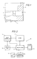
- FIG. 1 there is shown a store 1 in which there are stored several different images 2 to 8 of different size and rectangular shape.
- Store management programs are available which aim to store the images 2 to 8 in such a way as to reduce the number and size of unused areas of the store, such as areas 9, 10 and 11, created as a result of the difference in the sizes of the images 2 to 8.
- the management program might be configured such that in the first instance images are placed as near as possible to the top left hand corner of the store 1 (as represented in Figure 1).
- the program might be further configured such that when an image is removed from the store the remaining images are moved around within the store to occupy the vacated locations.
- the removal of say image 4 from the store 1 might cause the program to move image 7 and then move image 8 into the space previously occupied by image 7.
- a related problem is that of controlling the transfer of data from an image store for display of plural images on a monitor.
- the problem of plural image display is considered in British patent application GB-A-2174277 (IBM) which describes a display system in which a display screen is divided into multiple display rows and information relating to the image or images to be displayed in each row, including a start address and a boundary indicator for each image, is held in a store.
- IBM British patent application GB-A-2174277
- an electronic image processing system comprising: a store for storing image data representing a plurality of images as a multiplicity of pixels, the data for each image being stored as a one dimensional data list in a sequence of consecutive store addresses; a display screen having a multiplicity of display locations for displaying images represented by image data provided thereto; defining means for defining plural areas on the display screen in terms of data identifying plural vertical screen portions each having at least one associated horizontal screen portion and for identifying for each display area data for an image portion in terms of a start address in the store; calculating means for calculating for each display location from said horizontal and vertical screen portion data and said start address an address in the store at which data representing a pixel for display is stored; and reading means for reading the pixel data from the calculated store addresses and outputting the same to the display screen.
- a method of image processing comprising: storing image data representing a plurality of images as a multiplicity of pixels, the data for each image being stored as a one dimensional data list; defining plural areas on the display screen in terms of data identifying plural vertical screen portions each having at least one associated horizontal screen portion; identifying for each display area data for an image portion in terms of a start address of said stored data; calculating from said horizontal and vertical screen portion data and said start address an address of the stored data at which data representing a pixel for display is stored; and reading from the calculated address pixel data and outputting the same for display.
- the invention also provides an image processing system for displaying multiple images, the system comprising a controller for controlling the reading of data representing plural image portions from an image data store for display of the portions at respective areas on a monitor, the controller being arranged to identify in the image data store the data defining each of said image portions and to divide the monitor into a plurality of vertical zones each defined by a vertical start position and a vertical length and each having at least one associated horizontal zone defined by a horizontal start position and a horizontal length, the horizontal and vertical zones together defining said areas in which respective ones of said multiple image portions are to be displayed.
- an image processing system 10 comprising a dynamic random access memory image store 11 for storing data relating to one or more images.
- the store 11 is configured as a one dimensional array of storage locations each uniquely identified by a numerical address ranging from 0 (zero) to a maximum 2"-1, for example 2 32- 1 for a 32-bit addressing system.
- Image data from the store 11 is read for display of the image via a multiplexer 12 on a monitor 13.
- the reading of the data from the store 11 is controlled by a zone controller 14 and associated control RAM 15.
- the zone controller 14 controls access to the store 11 by controlling the addressing of storage locations within the store.
- the zone controller 14 comprises several ports, for example sixteen ports, each able to control access to a selected storage location within the store 11 for the reading of data therefrom and thereto.
- the system 10 also comprises independently controlled drawing processor 16, similar to that described in our British patent number 2,089,625, the teachings of which are incorporated herein by reference, and embodied in an image processing system marketed by us under the name PAINTBOX (Registered Trade Mark).
- the drawing processor 16 is thus responsive to user manipulations of a stylus/touch tablet device 17.
- the drawing processor 16 requests via the zone controller 14 data from the store 11 at locations determined by the position of the stylus on the touch tablet, modifies the data in order to change an image characteristic, e.g. colour, in the portion of the image represented thereby, and writes the modified data back to the same locations replacing the data previously stored there.
- the read-modify-write circuitry accesses the store via selected ports in the zone controller 14.
- the system may be required to display on the monitor 13 a picture showing several images represented by the data stored in the store 11.
- the monitor 13 will be capable of displaying images to a high definition television standard (HDTV), for example 1250 lines at 50Hz.
- An image to be displayed may be any size. It may for example be significantly smaller, i.e. comprise fewer picture elements than display locations on the monitor screen, it may be represented by a number of picture elements identical to the number of display locations available on the monitor screen, or it may comprise significantly more picture elements (e.g. 10,000 x 8,000 picture elements) than there are display locations on the monitor screen. In other words the image may have a resolution which is less than, equal to, or greater than the resolution of the monitor screen.
- the whole image may be displayed at a reduced resolution over the whole or a portion of the monitor screen; a portion of the image may be displayed at full resolution over the whole or a portion of the monitor screen; or a portion of the image may be displayed at less then full resolution over the whole or a portion of the monitor.
- This list is far from exhaustive.
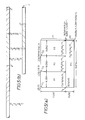
- FIG. 3(a) and (b) of the accompanying drawings data representing an image 18 of width W 1 pixels and height H 1 pixels is stored in raster scan order in the store 11 at a sequence of storage locations beginning at start address S 1 and ending at address (S 1 +H 1 ) ⁇ (W 1 -1).
- the zone controller 14 in Figure 2 generates addresses so that image data is scanned out of the store 11 in raster order for display on the monitor 13.
- the simplest task required of the zone controller is to scan out the data for display of the whole image on the monitor 13.
- the zone controller 14 will first address store location S 1 (as shown in Figure 3(a)) which contains data for the pixel in the top left hand corner of the image (as shown in Figure 3(b)) and will then step through locations S 1 +1, S 1 +2, S 1 +3 until it reaches location (S 1 +H 1 ).(W 1 -1) after which it will return to location S 1 and repeat the scan.
- a cut-out image portion 19 of width XLEN and height YLEN pixels may be defined for display on the monitor 13.
- the cut-out 19 has a start address S 1 ' in the store 11 at which data corresponding to the pixel at the top left-hand corner of the cut-out is stored.
- the data at address S 1 ' is read first and then the address is incremented to S 1 '+1 and then S 1 '+2 and so on until the data representing the last pixel in the first line in the cut-out has been read from address S i '+XLEN-1.
- the data for the first pixel in the second line is stored at location S 1 '+W in the store 11 and so this is the next location to be addressed in the store. (It should be noted here that the address is not S 1 '+XLEN. This is because it is the data forthe whole image 18 that is stored in scan order and not the data for the cut-out 19).
- each line of the cut-out 19 starts at an address one full width W 1 of the whole image 18 away from the address of the start of the previous line in the cut-out.
- This process of reading line portions corresponding to the cut out 19 is repeated until the data for the bottom right hand pixel of the cut out has been read from store location S 1 '- +YLEN W 1 +XLEN-1. All of the information necessary to perform the scan of the cut-out 19 is loaded into a memory within the zone controller as will be described in greater detail hereinafter.
- the scan is divided into two Y-zones Y1 and Y2.
- the Y-zones have widths XLEN1 and XLEN2 and heights YLEN1 and YLEN2.
- the widths XLEN1 and XLEN2 represent the number of display locations across the width of the monitor 13 and therefore XLEN1 and XLEN2 are equal to each other.
- the heights YLEN1 and YLEN2 together equal the heights, i.e. number of lines, of the Y-zones on the monitor 13.
- the stored images 20, 20a to be displayed have start addresses S 1 , S 2 , widths W 1 , W 2 and heights H 1 , H 2 and each stored image 20, 20a occupies its own sequence of addresses in the store 11 as illustrated in Figure 4(b) of the accompanying drawings.
- the zone controller is arranged to process the Y-zones in order, starting with zone Y1 and going on to zone Y2. More than two Y-zones may be defined if required.
- the zone controller first scans the store starting at address S 1 for display location [0, 0] and continuing through to address (S 1 +H 1 ).(W 1 -1) for display location [XLEN1-1, YLEN1-1], and then scans from address S 2 for display location [0, YLEN1] to address (S 2 +H 2 ).(W 2 -1) for display location [XLEN1+XLEN2-1, YLEN1+YLEN2-1].
- the stored images 20, 20a are larger than the areas in which they are to be displayed then a portion only of each of the two images will be required for display. Note that under these circumstances the values XLEN1, XLEN2, YLEN1 and YLEN2 will not all be the same as the corresponding sizes of the stored images W 1 , W 2 , H 1 , H 2 respectively.
- the first pixel of the image 20 to be displayed will be identified by a separate start address S 1 ' and the first pixel of the image 20a will be identified by a separate address S 2 ' and the zone controller will scan the store in a similar manner to that described with reference to Figure 3 hereinabove.
- the zone controller starts scanning from S1'forXLEN pixels, then proceeds to S 1 '+W 1 for a further XLEN pixels and then to S 1 '+2W 1 and so on until YLEN1 lines of pixels have been output.
- Image data representing a picture will usually define the picture to a high resolution and thus the image will appear crisp and sharp when viewed.
- the same level of resolution is however not required for defining images representing menus, palettes, etc. and it therefore makes sense to define such images at low resolution in order to free storage space within the store 11 for other uses.
- the zone controller is therefore arranged to be able to control the outputting of image data from the store such that the displayed image can be an enlarged version of the stored image, multiplied by a magnification factor M.
- Each Y-zone has its own magnification factor M and is arranged so that MxW for each zone is equal to the width of the display screen.
- the zone controller 14 of Figure 2 is further arranged so that one or more Y-zones can be divided horizontally into a number of X-zones.
- Figure 5(a) of the accompanying drawings there is shown an exemplary display configuration in which the screen of the monitor 13 is divided vertically in to two Y-zones Y1 and Y2 which extend across the width of the screen and have respective heights of YLEN1 and YLEN2 display lines.
- the first Y-zone Y1 is divided horizontally into three X-zones X1, X2, X3 having respective widths of XLEN1, XLEN2, XLEN3 display points.
- the second Y-zone is formed as a single X-zone having a width of XLEN4 display points corresponding to the width of the screen. Therefore the display point at the top lefthand corner of the first X-zone X1 is positioned at the top left-hand corner or origin [0,0] of the screen.
- the display point at the top left-hand corner of the second X-zone X2 is positioned at screen coordinate [XLEN1, 0] and similarly the display point at the top left-hand corner of the third X-zone X3 is positioned at screen co-ordinate [XLENI+XLEN2, 0].
- the bottom right hand corner of the third X-zone X3 is positioned at screen coordinate [XLEN1+XLEN2+XLEN3-1, YLEN1-1].
- the bottom right-hand corner of the fourth X-zone X4 is positioned at screen coordinate [XLEN4-1, YLEN1+YLEN2-1].
- each image or image portion is stored in the store as blocks of scan-sequential data and the zone controller 14 controls the reading of the data from the memory for display of the pixels represented thereby in the correct order to achieve the required display arrangement.
- the zone controller 14 controls the reading of the data from the memory for display of the pixels represented thereby in the correct order to achieve the required display arrangement.
- the displaying of the image and the data representing the image or the displayed image may be an enlarged version of the stored data in which case each pixel and each line will be replicated M n times where M n is the zoom factor M for the image occupying the nth X-zone.
- each displayed image may be the whole of the respective shared image, similar to the case described hereinabove, with reference to Figure 4, or it may be a portion of a larger image, similar to the case described hereinabove with reference to Figure 3.
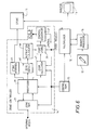
- FIG. 6 of the accompanying drawings shows the zone controller 14 in greater detail.
- the zone controller generates addresses which are used to access storage locations in the store 11 such that a screen full of pixels distributed in the store is assembled for display on the monitor.
- Each address is calculated either by adding an offset value to a base or start address S n or by replacing the previous base address S n with a new address S n+1 .
- Data defining the size of each zone and the location in the store 11 of respective images or image portions is stored in the control RAM 15.
- the zone controller 14 comprises a plurality of ports, e.g. sixteen ports, in parallel.
- the ports are operable individually such that for example control data can be transferred to one port whilst another port controls access to the store 11.
- four ports namely ports zero, one, eight and nine are used exclusively as video ports through which image data is transferred for display of the desired image or combined images on the monitor 13.
- Two of the ports say ports zero and one, are used for the display of odd-numbered display fields and the other two ports, say ports eight and nine, are used for the even-numbered fields. This enables one port to be used for example to control the reading of data for one scan cycle while the other is being loaded with control data to control the reading of data in the next scan cycle.
- ports are selected as required for example to control the transfer of data in read-modify-write operations, with one port being used in the reading of data and another port being used in the writing of modified data.
- ports are paired so as to share some common hardware. This means that both ports in a pair cannot be used at the same time, but they can be used in double-buffering operations, e.g. port two controlling loading of data while port ten controls the writing of data to the store 11 and vice versa. For t he sake of clarity only the elements of one port are shown in Figure 6.
- the zone controller 14 comprises an internal zone RAM 21 in which are stored sets of data for each port.
- the data sets contain all the information necessary to enable the above discussed and other display situations to be realised.
- the data sets are divided into separate blocks which in turn comprise plural data words which identify locations in the zone RAM 21 where otherdata words can be found and locations in the store 11 at which image data to be output to the monitor 13 is located.
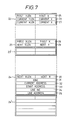
- external circuitry causes at least three data blocks, referred to herein as port block 22, Y-zone block 23 and X-zone block 24 as shown in Figure 7, to be loaded into the zone RAM 21.
- the data in the zone RAM is then ready for use by the zone controller when a port is selected.
- the port data block 22 comprises three fields of information 25-27.
- the first field 25 identifies the address in the zone RAM 21 at which the first Y-zone data block is located and the length of that Y-zone (YLEN1 in Figure 5).
- the second field 26 identifies the address in the zone RAM 21 at which the current Y-zone data block is located and the length of the current Y-zone
- the third field 27 identifies the address in the zone RAM 21 atwhich the currentX-zone is located together with the length of the current X-zone (XLEN in Figure 5).
- the Y-zone data block 23 only contains two data fields 28, 29 because it serves merely as a pointer to the data block for the X-zone.
- the first field 28 of the Y-zone block 23 identifies the address in RAM 21 at which thefirstX-zone data blockforthatY zone is located, together with the length of the first X-zone.
- the other field 29 identifies the address in the zone RAM 21 at which the next Y-zone data block is stored and the length of the next Y-zone.
- An X-zone data block e.g. block 24, contains all of the information needed to display an X-zone except for the zoom and scroll data which is defined separately.
- the X-zone data block 24 contains one field 30 which points to the address in RAM 21 at which the next X-zone data block is held, together with data identifying its length.
- the second field 31 of the X-zone data block identifies an increment value which determines the size of address increments when addressing the store to move along the line of data.
- the third field 32 contains the current address, that is to say the storage location in the store 11 currently being addressed by the zone controller.
- the fourth field 33 contains the start address of the X-zone and the fifth and sixth fields 34, 35 respectively identify the length of each line in the picture to be displayed (XLEN in Figure 5) and the address in the store 11 at which the current line in the X-zone starts.
- the zone RAM 21 provides up to Ik storage locations and thus has space for storing many separate port, X-zone and Y-zone data blocks for each of the ports provided in the zone controller.
- the zone controller 14 comprises a port store 36 in which is stored, at the end of a port operation, instruction data identifying the tasks to be performed by the port next time it is requested.
- the port store 36 transfers its data to a control sequencer 37 which responds to the instruction data by outputting control signals which control operation of the elements forming the zone controller 14 thereby causing the zone controller to execute the required task.
- control sequencer 37 that enables the zone controller to control the outputting of image data from the store.
- the control sequencer 37 is a microcontroller comprising a small microcode RAM (not shown) in which commands relating to different instruction sequences are stored.
- the instruction sequence executed by the control sequencer is selected depending on the length values in the various fields of the data blocks 22, 23, 24 discussed hereinabove with respect to Figure 7 of the accompanying drawings.
- the task of the zone controller 14 is to supervise the accessing of storage locations within the store 11 and thereby to control the reading of data from the store 11 to the monitor 13 to achieve the desired display of multiple images thereon.
- the zone controller 14 outputs, via the store interface 45, data representing the storage location of the present pixel required for display whilst calculating concurrently the storage location of the next pixel required for display.
- Operation of the zone controller is defined by a total of eight different instruction sequences under the control of the control sequencer 37.
- the eight instruction sequences are described in greater detail hereinafter and comprise a start sequence, an X-step sequence, a newX-zone sequence, an initialize X-zone sequence, a next-line sequence, a newY zone sequence, an end sequence, and a repeat-line sequence.
- the start sequence executable by the zone controller is represented by a sequence of data transfers in Figure 8 of the accompanying drawings.
- the first operation 38 performed in this initialising or start sequence is to cause a processor 39 (see Figure 6) to read the data from the RAM 21 identifying the address of the first Y-zone data block 23 from field 25 of the port block 22.
- the processor reads the data identifying the address of the first X-zone data block 24 from field 28 of the Y-zone block 23 in RAM 21.
- step 41 the data read from the field 25 is written into the second field 26 so that the current Y-zone is identified as the first Y-zone.
- step 42 the start address in field 33 of the X-zone data block 24 is read into the processor 39.
- the start address is written to each of fields 32 and 35 in steps 43a and 44 so that the current X address value in the port block 22 and the current address and the address in the X-zone block 24 are all set to the start address value of the first X block.
- the operation in step 43a of writing to the current address field 32 also causes the processor 39 to output the current address value to a store interface 45 (see Figure 6).
- the store interface 45 is connected to the store 11 and provides addresses to enable image data to be read from addressed locations to the multiplexer 12 for modification by the drawing processor 16 or for display of the image represented thereby on the monitor 13.
- the start sequence represented by Figure 8 initialises the data structures in the zone RAM at the start of a new display or drawing cycle.
- the start sequence only affects data relating to the first X and first Y zones. Where there are other X and/or Y-zones the data for the or each other zone is initialised by other sequences as will be described in greater detail hereinafter.
- zone controller 14 the other operations that can be executed by the zone controller 14 are controlled by similar microprogramme controlled data transfers to and from the zone RAM 21.
- the construction of such microprogramme controlled sequences are well within the ability of those possessed of the appropriate skills and accordingly the following description of the other seven operation sequences performed by the zone controller will not be given in such great detail.
- the X-step sequence causes the zone controller to generate a series of image store addresses so as to travel along a line of image points in a single X-zone.
- the control sequencer 37 causes the zone controller to add the value XINC (field 31 in X-zone block 24) to the address output via the store interface 45 to the image store and at the same time decrements the X-length value (field 27) to enable the end of the X-zone to be detected when the value reaches zero.
- the control sequencer causes the XLEN value to be read from the zone RAM 21 and thereafter to be output from the processor 39 to a zero detect circuit 49 (see Figure 6).
- the control sequencer 37 causes the zero detect circuit 49 to monitor for an XLEN value of zero and when such a value is detected this means that at least the end of a line in an X-zone has been reached.
- the zero detect circuit 49 also receives data relating to the YLEN (field 26 of port block 22) together with indications as to whether or not the current X and Y-zones are the last X and Y-zones.
- the zero detect circuit 49 passes the data it receives to an instruction calculator circuit 46 which analyses the data to determine which sequence should be executed next time by the zone controller.
- the instruction calculator46 causes the port store 36 to load the control sequencer 37 with microcode so that the new X-zone sequence is executed by the zone controller.
- the new X-zone sequence is arranged to look at the next X-zone pointer (field 30 in X-zone block 24) and set that value as the current X-zone value. It also adds the value Linelnc (field 34) to the X-zone current address (field 27) so that the current address is incremented by one lines worth of storage locations in the store 11. Thereafter, the above discussed X step sequence is executed by the zone controller under the control of the control sequencer 37.
- the above discussed newX-zone sequence is not used. Instead, an X-zone initialising sequence is executed which, instead of adding the value of Linelnc to the current address, copies of the start address from the X-zone data block (field 33) into the current address field 32 ready for use in the above discussed X step sequence.
- the length data in Fields 26 and 27 is decremented.
- the XLEN is decremented with each step along a line and the YLEN is decremented with each line step.
- the length data provides an indication of the length remaining in the current X or Y-zone.
- the zero detect circuit 49 and the instruction calculator 46 together detect this condition and cause the port store 36 to transfer to the control sequencer 37 microcode for generating addresses for the next line.
- the next-line control sequence identifies the first X-zone of the current Y-zone (from field 28) and then updates the value of the line address in field 35 from the address of the start of the previous line to the address of the start of the current line by adding to it the value Linelnc from field 34.
- the zero detect circuit 45 and instruction calculator46 respond by causing the port store 36 to load the control sequenc- erwith microcode for setting up the zone controller for a new Y-zone.
- the new Y-zone sequence identifies the next Y-zone by reading field 29 in Y-zone data block 23 and writing this data to field 25 of block 22.
- the next-Y data points to a new Y-zone data block 23' which contains a first X field that points to the start address of the data block 24' of the line first X-zone in the new Y-zone.
- the new Y-zone sequence identifies the new Y-zone and its firstX-zone and sets these up as the current Y and X-zones.
- the sequence also initialises data for the first X-zone by copying the start address in field 33 to the current X address field 27 and initialises the data for all X-zones in the Y-zone in a similar manner as the store addresses progress along this display line.
- the zone controller does not know whether the same port or another port will be requested next time round and so an end sequence is executed which saves the contents of the current Y and current X fields 26, 27 and places the port in a standby condition until such time as the port is again requested, forcing the start sequence to be run.
- the zone controller comprises a zoom calculator 47 which calculates when to repeat a line for a pixel-replicate vertical zoom by causing lines of addresses to be repeated.
- the zoom calculator 47 also calculates for a horizontal zoom whether new pixel data is needed or whether the previous pixel data is to be used again.
- the current XLEN is decremented and if new pixel data is required the current X address is recalculated.
- the repeat-line sequence executed by the sequencer 37 overrides the next-line sequence which would otherwise be run.
- the instruction calculator 46 decides that the next sequence to be performed should be the next-line sequence and causes the port store to pass the appropriate microcode to the sequencer. If, however, the zoom calculator 47 decides that the previous line should be repeated then the microcode selected by the instruction calculator is replaced by microcode defining the repeat-line sequence.
- the effect of the repeat-line sequence is to get the previous start of line value (field 35) from the zone RAM 21 and make that the current address (field 32), and to decrement the current YLEN value in field 26.
- the zone controller 14 co-operates with the multiplexer 12 (see Figure 2) in order to achieve horizontal pixel-replication zoom by sending horizontal scroll data from the control ramp to the multiplexer.
- the multiplexer 12 contains an accumulator (not shown) comprising a register which is loaded with a scroll value at the beginning of a line. The accumulator repeatedly adds a zoom value to the register and depending on the result decides whether or not the same pixel should be displayed more than once. Zoom calculations are carried out in the processor 39 at the beginning of a control sequence while the first values are being read from the zone RAM because during this period the processor is not occupied with zone calculations and therefore is free to be used for zoom calculations. An X-zoom is processed at the beginning of an X-step sequence, and a Y-zoom is processed at the beginning of a next-line sequence with the next line sequence being replaced by a repeat-line sequence if appropriate.
- zone controller 14 controls the addressing of pixel data in the one dimensional data lists in the store 11 fordis- play at display locations on a two dimensional display.
- the zone controller 14 serves simply to generate a patch of address values from the instantaneous position of the stylus on the touch tablet 17. Data from the control RAM is sent to the multiplexer 12 to tell it when to start and stop reading and writing to the addresses identified by the zone controller. None of the above discussed complex image data manipulations such as zoom need be performed by the zone controller during a read-modify-write operation and therefore there is no need to latch the control data in the zone controller.
Landscapes
- Engineering & Computer Science (AREA)
- Physics & Mathematics (AREA)
- Computer Hardware Design (AREA)
- General Physics & Mathematics (AREA)
- Theoretical Computer Science (AREA)
- Controls And Circuits For Display Device (AREA)
- Image Input (AREA)
- Digital Computer Display Output (AREA)
- Storing Facsimile Image Data (AREA)
Applications Claiming Priority (2)
| Application Number | Priority Date | Filing Date | Title |
|---|---|---|---|
| GB9215949A GB2269291B (en) | 1992-07-27 | 1992-07-27 | An electronic image processing system and method |
| GB9215949 | 1992-07-27 |
Publications (2)
| Publication Number | Publication Date |
|---|---|
| EP0581560A2 true EP0581560A2 (de) | 1994-02-02 |
| EP0581560A3 EP0581560A3 (de) | 1995-02-15 |
Family
ID=10719378
Family Applications (1)
| Application Number | Title | Priority Date | Filing Date |
|---|---|---|---|
| EP93305893A Withdrawn EP0581560A3 (de) | 1992-07-27 | 1993-07-26 | Elektronisches Bildverarbeitungssystem. |
Country Status (3)
| Country | Link |
|---|---|
| EP (1) | EP0581560A3 (de) |
| JP (1) | JPH06266830A (de) |
| GB (1) | GB2269291B (de) |
Family Cites Families (9)
| Publication number | Priority date | Publication date | Assignee | Title |
|---|---|---|---|---|
| JPS5655948A (en) * | 1979-10-12 | 1981-05-16 | Dainippon Screen Mfg Co Ltd | Image collecting method in image scanning recorder |
| JPS5981976A (ja) * | 1982-11-01 | 1984-05-11 | Dainippon Screen Mfg Co Ltd | 色分解画像走査記録装置 |
| US4533910A (en) * | 1982-11-02 | 1985-08-06 | Cadtrak Corporation | Graphics display system with viewports of arbitrary location and content |
| JPS60169851A (ja) * | 1984-02-13 | 1985-09-03 | Dainippon Screen Mfg Co Ltd | 画像走査記録装置における露光エリアの割付制御方法 |
| GB2172767B (en) * | 1985-01-31 | 1989-02-08 | Canon Kk | Image signal processing system |
| JPS61249086A (ja) * | 1985-04-26 | 1986-11-06 | インタ−ナショナル ビジネス マシ−ンズ コ−ポレ−ション | 隣接表示区域の画像表示装置 |
| US4812834A (en) * | 1985-08-01 | 1989-03-14 | Cadtrak Corporation | Graphics display system with arbitrary overlapping viewports |
| US4780709A (en) * | 1986-02-10 | 1988-10-25 | Intel Corporation | Display processor |
| US4947257A (en) * | 1988-10-04 | 1990-08-07 | Bell Communications Research, Inc. | Raster assembly processor |
-
1992
- 1992-07-27 GB GB9215949A patent/GB2269291B/en not_active Expired - Fee Related
-
1993
- 1993-07-26 EP EP93305893A patent/EP0581560A3/de not_active Withdrawn
- 1993-07-27 JP JP5185208A patent/JPH06266830A/ja not_active Withdrawn
Also Published As
| Publication number | Publication date |
|---|---|
| JPH06266830A (ja) | 1994-09-22 |
| GB2269291A (en) | 1994-02-02 |
| GB9215949D0 (en) | 1992-09-09 |
| GB2269291B (en) | 1996-04-24 |
| EP0581560A3 (de) | 1995-02-15 |
Similar Documents
| Publication | Publication Date | Title |
|---|---|---|
| KR0167116B1 (ko) | 변형가능한 디스플레이 메모리 제공방법 및 장치 | |
| EP0404373B1 (de) | Bildverschiebung mit variabler Geschwindigkeit | |
| EP0133903B1 (de) | Verfahren und Vorrichtung zum Steuern einer Anzeige | |
| US4670752A (en) | Hard-wired circuit for handling screen windows | |
| EP0447225B1 (de) | Verfahren und Einrichtung zur Maximierung von Spaltenadressenkohärenz für den Zugriff von seriellen und Direktzugriffstoren in einem graphischen System mit einem Rasterpufferspeicher | |
| EP0012420A1 (de) | Verfahren und Vorrichtung zur Ansteuerung Anzeigevorrichtungen | |
| GB2250615A (en) | Direct memory access controller | |
| EP0895187A2 (de) | Verfahren zur massstäblichen Umformung von Bildern | |
| EP0279229A2 (de) | Grafik-Anzeigesystem | |
| CA1220293A (en) | Raster scan digital display system | |
| EP0279225A2 (de) | Zähler mit veränderbarer Verschaltung zur Adressierung in graphischen Anzeigesystemen | |
| EP0200036A2 (de) | Verfahren und System zur Anzeige von Bildern in benachbarten Bereichen | |
| US8023359B2 (en) | System and method for converting scan data | |
| US5657047A (en) | Method and apparatus for zooming images on a video display | |
| EP0581560A2 (de) | Elektronisches Bildverarbeitungssystem | |
| JPH0616230B2 (ja) | マルチスクリ−ン表示方法 | |
| JPH0731489B2 (ja) | メモリ・アレイのアクセス方法 | |
| KR960003072B1 (ko) | 폰트 데이타 처리장치 | |
| JPS6232491A (ja) | Crt表示装置 | |
| JPH0764524A (ja) | 画像表示装置 | |
| JP2821121B2 (ja) | 表示制御装置 | |
| JP2000354200A (ja) | 画像処理装置および画像処理方法ならびに画像処理プログラムを記録したコンピュータ読み取り可能な情報記録媒体 | |
| JPH09244620A (ja) | 画像メモリおよび画像表示システム | |
| JPH0443595B2 (de) | ||
| JPS59219784A (ja) | 大仮想画面の表示制御装置 |
Legal Events
| Date | Code | Title | Description |
|---|---|---|---|
| PUAI | Public reference made under article 153(3) epc to a published international application that has entered the european phase |
Free format text: ORIGINAL CODE: 0009012 |
|
| AK | Designated contracting states |
Kind code of ref document: A2 Designated state(s): DE FR GB IT |
|
| PUAL | Search report despatched |
Free format text: ORIGINAL CODE: 0009013 |
|
| AK | Designated contracting states |
Kind code of ref document: A3 Designated state(s): DE FR GB IT |
|
| 17P | Request for examination filed |
Effective date: 19950426 |
|
| 17Q | First examination report despatched |
Effective date: 19960628 |
|
| STAA | Information on the status of an ep patent application or granted ep patent |
Free format text: STATUS: THE APPLICATION IS DEEMED TO BE WITHDRAWN |
|
| 18D | Application deemed to be withdrawn |
Effective date: 19971104 |