EP0582547A1 - Appareil pour l'acquisition d'images avec compensation de la vitesse - Google Patents
Appareil pour l'acquisition d'images avec compensation de la vitesse Download PDFInfo
- Publication number
- EP0582547A1 EP0582547A1 EP93810533A EP93810533A EP0582547A1 EP 0582547 A1 EP0582547 A1 EP 0582547A1 EP 93810533 A EP93810533 A EP 93810533A EP 93810533 A EP93810533 A EP 93810533A EP 0582547 A1 EP0582547 A1 EP 0582547A1
- Authority
- EP
- European Patent Office
- Prior art keywords
- speed
- sensor
- scanning
- signals
- stream
- Prior art date
- Legal status (The legal status is an assumption and is not a legal conclusion. Google has not performed a legal analysis and makes no representation as to the accuracy of the status listed.)
- Granted
Links
Images

Classifications
-
- G—PHYSICS
- G06—COMPUTING OR CALCULATING; COUNTING
- G06T—IMAGE DATA PROCESSING OR GENERATION, IN GENERAL
- G06T1/00—General purpose image data processing
- G06T1/0007—Image acquisition
-
- H—ELECTRICITY
- H04—ELECTRIC COMMUNICATION TECHNIQUE
- H04N—PICTORIAL COMMUNICATION, e.g. TELEVISION
- H04N1/00—Scanning, transmission or reproduction of documents or the like, e.g. facsimile transmission; Details thereof
- H04N1/40—Picture signal circuits
Definitions
- This invention pertains to an image acquisition system, and more particularly to an apparatus used for the acquisition of images of a plurality of printed sheets arranged as a continuous web or a plurality of cut printed sheets fed continuously, to determine whether these printed sheets are acceptable, said apparatus including means for compensating for the speed of the sheets.
- Printed sheets may be checked and validated using a device having a transport mechanism for transporting the sheets at a nominal speed past a stationary position, and scanning them with sensor means to generate electronic images thereof.
- the scanning may be accomplished using solid state sensors such as CCDs (Charge Coupled Devices) arranged to scan a line, self scanning silicon photodiode linear arrays, including integrating photodiode elements, or other single, linear, two-dimensional array integrating sensors, and so on.
- CCDs Charge Coupled Devices
- self scanning silicon photodiode linear arrays including integrating photodiode elements, or other single, linear, two-dimensional array integrating sensors, and so on.
- the sensor integration sampling rate is held constant, all these devices are unacceptable because they produce images with geometric distortion due to the variations in the speed of the object being scanned.
- previous devices have included a synchronization device, such as a shaft encoder, on the motivating transport to synchronize the sampling rate to the motion.
- a synchronization device such as a shaft encoder
- the value of the signal coming from the scanning means is not consistent because the signal is integrated over the sampling period making it proportional to the amount of light reaching the sensor and to the amount of time between samples. Therefore, variation in the movement of the sheet being scanned results in a proportional distortion of the signal.
- AGC Automatic Gain Control
- an objective of the present invention is to provide an image acquisition system wherein the images obtained from the scanning means are stabilized to compensate for variations in the speed of the moving object being scanned.
- a further objective is to provide an automatic speed compensation apparatus which is capable of handling speed variations of a wide range.
- an image acquisition apparatus constructed in accordance with this invention, consists of a transport mechanism for transporting an object past a sensor, and sensor control means for controlling the operation of the sensor.
- the speed of the transport mechanism is constantly monitored and a speed multiplier output signal is generated indicative of the transport mechanism speed. This output is used to scale the amplitude of the scanner output to compensate for speed variations of the transport mechanism. If the speed dips below a preset threshold, such as 50%, the sampling rate of the scanner may also be increased, and additional computation performed to compensate for the change in sampling rate.
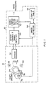
- the scanning station includes a drum 22, having a cylindrical surface 24 which carries a sheet 12 and rotating about an axis 26.
- Several lamps 28, 30 are used to illuminate sheet 12.
- a scanning means or sensor 32 is used to scan sheet 12 through a lens 34 which focuses an image of the sheet 12 onto the sensor.
- the sensor may consist for example of a linear array of CCDs (Charge-Coupled-Devices) arranged to scan essentially a single line extending along the width of the sheet 12 and is controlled by a sensor control and amplifier circuit 34.
- CCDs Charge-Coupled-Devices
- a shaft encoder 36 is connected to the drum 22 and acts as a synchronization device. Signals from the shaft encoder 36 are routed to the sensor control circuit 34 to synchronize the sampling of the sensor output.
- the sensor control circuit 34 contains the timing control for operation of the sensor 32, and amplification and signal conditioning of the sensor output and may perform conversion to digital information. Geometric distortion is removed by sampling the sensor signal at precise intervals of scanning motion, the line spacing, and reading the sensor data.
- the output of the shaft encoder 36 is also routed to a speed detector circuit.
- the speed detector circuit performs signal conditioning, filtering, speed determination, and processing on the shaft encoder signal to produce a speed multiplier output.
- This output and the output of the sensor control circuit are multiplied together in a multiplier circuit 40 to exactly compensate the sensor signal for variations in the speed of drum 22 as discussed more fully below. This compensation can be precise because the sample period and the multiplier are based on identical data from the shaft encoder synchronization device.
- the sensor 32 and sensor control and signal amplifier circuit 34 operate to generate at a certain preselected rate determined by the physical characteristics of the sensor, the data handling capabilities of the processor 20, and so on.
- the information from sensor 32 is provided as a data stream corresponding to a scanned line.
- the data processor 20 assembles this data to generate an image of the sample.
- multiplier 40 is used to adjust the amplitude of the signals from sensor control and signal amplifier circuit 34 to compensate for the speed variation of drum 22.
- speed detector 38 generates a speed multiplier output which is selected to scale the amplitudes of the output of sensor 32 to compensate for the speed variation of drum 22. For example, if the drum revolves at a speed which is 5% higher than its normal speed, the output of sensor control circuit 34 is reduced by 5%. Speed detector 38 will supply a multiplier value corresponding to 105%. which when multiplying the reduced value from circuit 34 compensates for the increased speed.
- speed detector 38 may include means of determining the proper scaling multiplier for the sensor 32, such as for example, a look-up table 44.
- the embodiment of Figure 1 allows accurate scanning of objects with a speed range of about 2:1. However, a much wider speed range acquisition can be attained by an enhancement of the invention illustrated in Figure 2.
- the illuminated sheet 22 is moved in front of a lens 34 which focuses the image of the sheet on the sensor 32. Signals from the shaft encoder 36 are routed to the speed detector circuit 38.
- the speed detector circuit performs signal conditioning, filtering, and speed determination as before.
- the detected speed is analyzed to determine a speed range. If the transport speed is in the range between one-half the maximum rate and the maximum rate, the sensor control is operated conventionally: signals sent to the sensor control instruct it to sample and scan the sheet 22 once per each line spacing.
- the speed detector computes a speed multiplier output which is multiplied by the sensor value to exactly compensate the sensor signal for variations in the sample period.
- the speed detector sends a signal to an accumulator circuit 42 to pass the data unchanged. In this speed range, this implementation operates identically to the apparatus described in the first embodiment description.
- the speed detector When the speed detector senses a transport speed less than one-half the maximum, but more than one-quarter the maximum, synchronized signals are sent to the sensor control, multiplier and accumulator. Under these circumstances, the sensor 32 may be overloaded because of the excessive scan time period.
- the scan period is reduced as follows. In this speed range, the sensor control samples and reads out the sensor twice per each line spacing.
- the speed detector determines a speed multiplier output which exactly compensates the sensor signal for variations in the now shortened scan period. This computation may involve the use of look-up table 44 as described above.
- the speed detector sends a signal to the accumulator circuit 42 to accumulate pairs of sensor samples.
- the accumulator 42 combines the two sample sets for each scanned line to derive a composite sampled set for that line.
- sensor 32 may include 8,000 sensor elements arranged to produce normally a stream of 8,000 signals representing a scan line across sheet 22, when the drum is rotating at its normal speed. These signals after suitable A/D conversation are fed by sensor control and amplification circuit 34 to the speed compensation multiplier 40. If the speed of drum 12 drops to about half of its speed, then the scanning rate of sensor 32 is doubled to produce two streams of 8,000 signals for each scan line. These two streams, after scaling by multiplier 40 are combined, two at a time (for example, by addition and division by 2) by accumulator 42 to produce a single stream of 8,000 signals for the processor.
- the speed detector When the speed detector senses a transport speed less than one-quarter the maximum, but more than one-eighth the maximum, signals are sent to the sensor control, multiplier and accumulator. In this speed range, the sensor control samples and reads out the sensor four times per each line. The speed detector computes a speed multiplier output which exactly compensates the sensor signal for variations in the shortened sample period. The speed detector sends a signal to the accumulator circuit 42 to accumulate sets of four sensor samples, divide the result by four, and send this final data to the processor for analysis.
- This principle is applied continuously as the transport speed is reduced to obtain an arbitrary speed dynamic range, with the speed sensor determining a speed range, sub-line spacing, speed compensation multiplier, accumulation control and divide control. Over this range, the integration time of the sensor is held within a 2:1 range, preserving signal to noise ratio and simplifying the sensor electronics while maintaining geometric and photometric accuracy of the data used by the rest of the system.
Landscapes
- Engineering & Computer Science (AREA)
- Multimedia (AREA)
- Signal Processing (AREA)
- General Physics & Mathematics (AREA)
- Theoretical Computer Science (AREA)
- Physics & Mathematics (AREA)
- Facsimile Scanning Arrangements (AREA)
- Image Input (AREA)
- Apparatus For Radiation Diagnosis (AREA)
- Ultra Sonic Daignosis Equipment (AREA)
- Instruments For Viewing The Inside Of Hollow Bodies (AREA)
- Adjustment Of Camera Lenses (AREA)
- Magnetic Resonance Imaging Apparatus (AREA)
- Closed-Circuit Television Systems (AREA)
- Photoreceptors In Electrophotography (AREA)
Applications Claiming Priority (2)
| Application Number | Priority Date | Filing Date | Title |
|---|---|---|---|
| US926775 | 1992-08-06 | ||
| US07/926,775 US5530562A (en) | 1992-08-06 | 1992-08-06 | Apparatus for image acquisition with speed compensation |
Publications (2)
| Publication Number | Publication Date |
|---|---|
| EP0582547A1 true EP0582547A1 (fr) | 1994-02-09 |
| EP0582547B1 EP0582547B1 (fr) | 1998-09-30 |
Family
ID=25453703
Family Applications (1)
| Application Number | Title | Priority Date | Filing Date |
|---|---|---|---|
| EP93810533A Expired - Lifetime EP0582547B1 (fr) | 1992-08-06 | 1993-07-26 | Appareil pour l'acquisition d'images avec compensation de la vitesse |
Country Status (11)
| Country | Link |
|---|---|
| US (1) | US5530562A (fr) |
| EP (1) | EP0582547B1 (fr) |
| JP (1) | JP3316041B2 (fr) |
| KR (1) | KR100280029B1 (fr) |
| CN (1) | CN1040826C (fr) |
| AT (1) | ATE171830T1 (fr) |
| AU (1) | AU667931B2 (fr) |
| CA (1) | CA2100321C (fr) |
| DE (1) | DE69321313T2 (fr) |
| RU (1) | RU2128403C1 (fr) |
| UA (1) | UA42673C2 (fr) |
Cited By (4)
| Publication number | Priority date | Publication date | Assignee | Title |
|---|---|---|---|---|
| WO2001017225A1 (fr) * | 1999-08-30 | 2001-03-08 | Gateway, Inc. | Scanneur de supports |
| US6570956B1 (en) | 2000-11-27 | 2003-05-27 | Jin-Koo Rhee | Searching system using X-ray and millimeter-wave signal |
| US7869623B2 (en) | 2004-04-22 | 2011-01-11 | Kba-Giori S.A. | Inspection machine and process |
| EP2305488A1 (fr) | 2004-04-22 | 2011-04-06 | KBA-NotaSys SA | Unité de perforation au laser et procédé de production |
Families Citing this family (8)
| Publication number | Priority date | Publication date | Assignee | Title |
|---|---|---|---|---|
| JP3421129B2 (ja) * | 1994-05-13 | 2003-06-30 | ブラザー工業株式会社 | 画像読取装置 |
| CN1061200C (zh) * | 1996-07-31 | 2001-01-24 | 明碁电脑股份有限公司 | 调整扫描仪扫描速度的方法 |
| JP3060978B2 (ja) * | 1997-02-10 | 2000-07-10 | 日本電気株式会社 | 画像処理装置 |
| JP3521303B2 (ja) * | 1997-10-31 | 2004-04-19 | ブラザー工業株式会社 | 光学走査装置 |
| RU2206183C1 (ru) * | 2001-11-27 | 2003-06-10 | Закрытое акционерное общество "КРОК инкорпорейтед" | Промышленный сканер |
| RU2321963C1 (ru) * | 2006-08-04 | 2008-04-10 | Самсунг Электроникс Ко., Лтд. | Сканер |
| CN201491107U (zh) * | 2009-07-20 | 2010-05-26 | 吴伟佳 | 带有速度记录和补偿模块的图像扫描装置 |
| KR101763945B1 (ko) * | 2011-02-18 | 2017-08-14 | 엘지디스플레이 주식회사 | 입체영상 표시장치 및 그의 크로스토크 보상방법 |
Citations (2)
| Publication number | Priority date | Publication date | Assignee | Title |
|---|---|---|---|---|
| JPS60133415A (ja) * | 1983-12-21 | 1985-07-16 | Dainippon Screen Mfg Co Ltd | 画像記録方法 |
| WO1991015919A2 (fr) * | 1990-04-06 | 1991-10-17 | S & R Tech Development, Inc. | Lecteur avec compensation electronique de non linearite et procede de traitement de donnees d'images |
Family Cites Families (15)
| Publication number | Priority date | Publication date | Assignee | Title |
|---|---|---|---|---|
| DE265724C (fr) * | ||||
| US3560651A (en) * | 1967-11-08 | 1971-02-02 | Xerox Corp | Mechanical feedback for facsimile scanning system |
| DE2413034C3 (de) * | 1974-03-19 | 1983-11-17 | Dr.-Ing. Rudolf Hell Gmbh, 2300 Kiel | Verfahren und Anordnung zur Vermeidung von Fehlern bei der Reproduktion von Bildvorlagen |
| US4034407A (en) * | 1976-02-17 | 1977-07-05 | Xerox Corporation | Scan interlock system |
| JPS5427559A (en) * | 1977-07-29 | 1979-03-01 | Kumiai Chem Ind Co Ltd | 1-(4-butyl) benzoylpyrrolidine and bactericides containing the same |
| JPS5855712B2 (ja) * | 1977-02-07 | 1983-12-10 | 松下電器産業株式会社 | ファクシミリ走査方式 |
| JPS58196190A (ja) * | 1982-05-11 | 1983-11-15 | Kawasaki Heavy Ind Ltd | 止留溶接方法 |
| US4591727A (en) * | 1983-11-14 | 1986-05-27 | International Business Machines Corporation | Solid state scanner for a variable speed transport |
| DE3783984T2 (de) * | 1986-09-16 | 1993-05-19 | Matsushita Electric Ind Co Ltd | Kopierer mit positionskontrollierbarer subabtasteinrichtung. |
| JP2817909B2 (ja) * | 1987-01-27 | 1998-10-30 | キヤノン株式会社 | 画像読取装置 |
| JPH0620222B2 (ja) * | 1987-07-30 | 1994-03-16 | 大日本スクリ−ン製造株式会社 | 画像走査読取り装置の受光部の感度基準設定方法 |
| US4776021A (en) * | 1987-11-16 | 1988-10-04 | Ncr Corporation | Speed compensation scheme for reading MICR data |
| US5014324A (en) * | 1987-12-21 | 1991-05-07 | Ncr Corporation | MICR character reader using magnetic peaks to update timing clocks |
| JPH02151258A (ja) * | 1988-11-30 | 1990-06-11 | Sharp Corp | 直線駆動装置 |
| US5047871A (en) * | 1989-05-23 | 1991-09-10 | Hewlett-Packard Company | Direction scaling method and apparatus for image scanning resolution control |
-
1992
- 1992-08-06 US US07/926,775 patent/US5530562A/en not_active Expired - Lifetime
-
1993
- 1993-07-12 CA CA002100321A patent/CA2100321C/fr not_active Expired - Lifetime
- 1993-07-26 DE DE69321313T patent/DE69321313T2/de not_active Expired - Lifetime
- 1993-07-26 AT AT93810533T patent/ATE171830T1/de not_active IP Right Cessation
- 1993-07-26 EP EP93810533A patent/EP0582547B1/fr not_active Expired - Lifetime
- 1993-07-27 AU AU44214/93A patent/AU667931B2/en not_active Ceased
- 1993-08-04 UA UA93003183A patent/UA42673C2/uk unknown
- 1993-08-05 JP JP19453393A patent/JP3316041B2/ja not_active Expired - Fee Related
- 1993-08-05 RU RU93049325A patent/RU2128403C1/ru active
- 1993-08-05 CN CN93109650A patent/CN1040826C/zh not_active Expired - Lifetime
- 1993-08-05 KR KR1019930015198A patent/KR100280029B1/ko not_active Expired - Lifetime
Patent Citations (2)
| Publication number | Priority date | Publication date | Assignee | Title |
|---|---|---|---|---|
| JPS60133415A (ja) * | 1983-12-21 | 1985-07-16 | Dainippon Screen Mfg Co Ltd | 画像記録方法 |
| WO1991015919A2 (fr) * | 1990-04-06 | 1991-10-17 | S & R Tech Development, Inc. | Lecteur avec compensation electronique de non linearite et procede de traitement de donnees d'images |
Non-Patent Citations (1)
| Title |
|---|
| PATENT ABSTRACTS OF JAPAN vol. 009, no. 296 (P - 407) 22 November 1985 (1985-11-22) * |
Cited By (7)
| Publication number | Priority date | Publication date | Assignee | Title |
|---|---|---|---|---|
| WO2001017225A1 (fr) * | 1999-08-30 | 2001-03-08 | Gateway, Inc. | Scanneur de supports |
| US6297491B1 (en) | 1999-08-30 | 2001-10-02 | Gateway, Inc. | Media scanner |
| US6504138B1 (en) * | 1999-08-30 | 2003-01-07 | Gateway, Inc. | Media scanner |
| US6570956B1 (en) | 2000-11-27 | 2003-05-27 | Jin-Koo Rhee | Searching system using X-ray and millimeter-wave signal |
| US7869623B2 (en) | 2004-04-22 | 2011-01-11 | Kba-Giori S.A. | Inspection machine and process |
| EP2305488A1 (fr) | 2004-04-22 | 2011-04-06 | KBA-NotaSys SA | Unité de perforation au laser et procédé de production |
| US9849711B2 (en) | 2004-04-22 | 2017-12-26 | Kba-Giori S.A. | Printing machine with laser perforating |
Also Published As
| Publication number | Publication date |
|---|---|
| CN1040826C (zh) | 1998-11-18 |
| EP0582547B1 (fr) | 1998-09-30 |
| CN1083645A (zh) | 1994-03-09 |
| JPH06215114A (ja) | 1994-08-05 |
| AU4421493A (en) | 1994-02-10 |
| JP3316041B2 (ja) | 2002-08-19 |
| CA2100321C (fr) | 2004-06-01 |
| KR940005075A (ko) | 1994-03-16 |
| KR100280029B1 (ko) | 2001-02-01 |
| ATE171830T1 (de) | 1998-10-15 |
| AU667931B2 (en) | 1996-04-18 |
| DE69321313D1 (de) | 1998-11-05 |
| US5530562A (en) | 1996-06-25 |
| RU2128403C1 (ru) | 1999-03-27 |
| UA42673C2 (uk) | 2001-11-15 |
| CA2100321A1 (fr) | 1994-02-07 |
| DE69321313T2 (de) | 1999-05-06 |
Similar Documents
| Publication | Publication Date | Title |
|---|---|---|
| EP0369585B1 (fr) | Moniteur à caméra vidéo | |
| EP0471444B1 (fr) | Caméra vidéo | |
| US5530562A (en) | Apparatus for image acquisition with speed compensation | |
| EP0366235B1 (fr) | Procédé et dispositif de surveillance | |
| US4724481A (en) | Flaw detector for detecting flaws in a sheet | |
| USH1616H (en) | Web inspection system having enhanced video signal preprocessing | |
| US5117295A (en) | Structure for and method of scanning with multiplexed light sensor arrays | |
| USRE36047E (en) | Multi-mode TDI/raster-scan television camera system | |
| US20010000909A1 (en) | Method and apparatus for checking shape | |
| EP0327229B1 (fr) | Circuit et procédé de traitement de signaux | |
| US4893345A (en) | Method for detecting/processing image information | |
| JPS61219648A (ja) | 印刷物の検査装置 | |
| GB2358979A (en) | Exposure control system for a moving target | |
| JP2584747B2 (ja) | 画像処理装置 | |
| JPS6339400B2 (fr) | ||
| JPH0949713A (ja) | 平面形状計 | |
| JPS62221085A (ja) | 自己走査型光電変換検出装置 | |
| JPH05240775A (ja) | 血液等の凝集パターン出力装置 | |
| JP2006170928A (ja) | イメージセンサの校正方法 | |
| JPH05130497A (ja) | 1次元画像処理システム | |
| JPH0448024B2 (fr) | ||
| JPH05115044A (ja) | 信号処理回路の利得調整方式 | |
| JPH06152884A (ja) | 画像入力装置 | |
| JPH0965172A (ja) | 画像検出装置 | |
| JPH01246674A (ja) | 画像検査装置 |
Legal Events
| Date | Code | Title | Description |
|---|---|---|---|
| PUAI | Public reference made under article 153(3) epc to a published international application that has entered the european phase |
Free format text: ORIGINAL CODE: 0009012 |
|
| AK | Designated contracting states |
Kind code of ref document: A1 Designated state(s): AT CH DE FR GB IT LI SE |
|
| 17P | Request for examination filed |
Effective date: 19940630 |
|
| 17Q | First examination report despatched |
Effective date: 19960722 |
|
| GRAG | Despatch of communication of intention to grant |
Free format text: ORIGINAL CODE: EPIDOS AGRA |
|
| GRAG | Despatch of communication of intention to grant |
Free format text: ORIGINAL CODE: EPIDOS AGRA |
|
| GRAH | Despatch of communication of intention to grant a patent |
Free format text: ORIGINAL CODE: EPIDOS IGRA |
|
| GRAH | Despatch of communication of intention to grant a patent |
Free format text: ORIGINAL CODE: EPIDOS IGRA |
|
| GRAA | (expected) grant |
Free format text: ORIGINAL CODE: 0009210 |
|
| AK | Designated contracting states |
Kind code of ref document: B1 Designated state(s): AT CH DE FR GB IT LI SE |
|
| REF | Corresponds to: |
Ref document number: 171830 Country of ref document: AT Date of ref document: 19981015 Kind code of ref document: T |
|
| REG | Reference to a national code |
Ref country code: CH Ref legal event code: EP |
|
| REF | Corresponds to: |
Ref document number: 69321313 Country of ref document: DE Date of ref document: 19981105 |
|
| ET | Fr: translation filed | ||
| PLBE | No opposition filed within time limit |
Free format text: ORIGINAL CODE: 0009261 |
|
| STAA | Information on the status of an ep patent application or granted ep patent |
Free format text: STATUS: NO OPPOSITION FILED WITHIN TIME LIMIT |
|
| 26N | No opposition filed | ||
| REG | Reference to a national code |
Ref country code: GB Ref legal event code: IF02 |
|
| PGFP | Annual fee paid to national office [announced via postgrant information from national office to epo] |
Ref country code: SE Payment date: 20090722 Year of fee payment: 17 Ref country code: AT Payment date: 20090724 Year of fee payment: 17 |
|
| REG | Reference to a national code |
Ref country code: CH Ref legal event code: PFA Owner name: BA-GIORI S.A. Free format text: KBA-GIORI S.A.#4, RUE DE LA PAIX#1003 LAUSANNE (CH) -TRANSFER TO- KBA-GIORI S.A.#AVENUE DU GREY 55 CASE POSTALE 347#1000 LAUSANNE 22 (CH) |
|
| REG | Reference to a national code |
Ref country code: CH Ref legal event code: PFA Owner name: KBA-NOTASYS SA Free format text: KBA-GIORI S.A.#AVENUE DU GREY 55 CASE POSTALE 347#1000 LAUSANNE 22 (CH) -TRANSFER TO- KBA-NOTASYS SA#AVENUE DU GREY 55 CASE POSTALE 347#1000 LAUSANNE 22 (CH) |
|
| PG25 | Lapsed in a contracting state [announced via postgrant information from national office to epo] |
Ref country code: AT Free format text: LAPSE BECAUSE OF NON-PAYMENT OF DUE FEES Effective date: 20100726 |
|
| PGFP | Annual fee paid to national office [announced via postgrant information from national office to epo] |
Ref country code: CH Payment date: 20110830 Year of fee payment: 19 |
|
| REG | Reference to a national code |
Ref country code: DE Ref legal event code: R082 Ref document number: 69321313 Country of ref document: DE Representative=s name: REBLE & KLOSE RECHTS- UND PATENTANWAELTE, DE Effective date: 20111222 Ref country code: DE Ref legal event code: R081 Ref document number: 69321313 Country of ref document: DE Owner name: KBA-NOTASYS SA, CH Free format text: FORMER OWNER: KBA-GIORI S.A., LAUSANNE, CH Effective date: 20111222 |
|
| PG25 | Lapsed in a contracting state [announced via postgrant information from national office to epo] |
Ref country code: SE Free format text: LAPSE BECAUSE OF NON-PAYMENT OF DUE FEES Effective date: 20100727 |
|
| PGFP | Annual fee paid to national office [announced via postgrant information from national office to epo] |
Ref country code: GB Payment date: 20120726 Year of fee payment: 20 |
|
| PGFP | Annual fee paid to national office [announced via postgrant information from national office to epo] |
Ref country code: FR Payment date: 20120808 Year of fee payment: 20 Ref country code: IT Payment date: 20120727 Year of fee payment: 20 Ref country code: DE Payment date: 20120809 Year of fee payment: 20 |
|
| REG | Reference to a national code |
Ref country code: DE Ref legal event code: R071 Ref document number: 69321313 Country of ref document: DE |
|
| REG | Reference to a national code |
Ref country code: CH Ref legal event code: PL |
|
| REG | Reference to a national code |
Ref country code: GB Ref legal event code: PE20 Expiry date: 20130725 |
|
| PG25 | Lapsed in a contracting state [announced via postgrant information from national office to epo] |
Ref country code: DE Free format text: LAPSE BECAUSE OF EXPIRATION OF PROTECTION Effective date: 20130727 |
|
| PG25 | Lapsed in a contracting state [announced via postgrant information from national office to epo] |
Ref country code: GB Free format text: LAPSE BECAUSE OF EXPIRATION OF PROTECTION Effective date: 20130725 |