EP0590120B1 - Procede et dispositif permettant de changer plus aisement une chaine - Google Patents
Procede et dispositif permettant de changer plus aisement une chaine Download PDFInfo
- Publication number
- EP0590120B1 EP0590120B1 EP93907744A EP93907744A EP0590120B1 EP 0590120 B1 EP0590120 B1 EP 0590120B1 EP 93907744 A EP93907744 A EP 93907744A EP 93907744 A EP93907744 A EP 93907744A EP 0590120 B1 EP0590120 B1 EP 0590120B1
- Authority
- EP
- European Patent Office
- Prior art keywords
- warp
- roller
- frame
- clamping
- woven
- Prior art date
- Legal status (The legal status is an assumption and is not a legal conclusion. Google has not performed a legal analysis and makes no representation as to the accuracy of the status listed.)
- Expired - Lifetime
Links
- 238000000034 method Methods 0.000 title claims description 13
- 230000008569 process Effects 0.000 title description 2
- 238000009941 weaving Methods 0.000 claims abstract description 27
- 238000004804 winding Methods 0.000 claims description 24
- 230000008859 change Effects 0.000 claims description 7
- 229910000831 Steel Inorganic materials 0.000 claims description 3
- 239000010959 steel Substances 0.000 claims description 3
- XAGFODPZIPBFFR-UHFFFAOYSA-N aluminium Chemical compound [Al] XAGFODPZIPBFFR-UHFFFAOYSA-N 0.000 description 2
- 229910052782 aluminium Inorganic materials 0.000 description 2
- 238000006073 displacement reaction Methods 0.000 description 2
- 238000009940 knitting Methods 0.000 description 2
- 230000009467 reduction Effects 0.000 description 2
- 239000000969 carrier Substances 0.000 description 1
- 230000000694 effects Effects 0.000 description 1
- 230000007246 mechanism Effects 0.000 description 1
- 230000035899 viability Effects 0.000 description 1
Images
Classifications
-
- D—TEXTILES; PAPER
- D03—WEAVING
- D03J—AUXILIARY WEAVING APPARATUS; WEAVERS' TOOLS; SHUTTLES
- D03J1/00—Auxiliary apparatus combined with or associated with looms
- D03J1/16—Apparatus for joining warp ends
- D03J1/18—Apparatus for joining warp ends for joining, e.g. tying, a complete series of fresh warp threads to the used warp threads
-
- D—TEXTILES; PAPER
- D03—WEAVING
- D03J—AUXILIARY WEAVING APPARATUS; WEAVERS' TOOLS; SHUTTLES
- D03J1/00—Auxiliary apparatus combined with or associated with looms
- D03J1/001—Cloth or warp beam replacement
Definitions
- the invention is in the field of warp changing on weaving machines by attaching a new one to the old, woven chain, the old chain being used to remove warp thread crossings and to release sized warp threads on their last piece over a length of about 1.5 to 2 m is pulled through the dishes and wound up. This prepares the old chain in such a way that the quality of the tying operation is positively influenced and in particular can be knotted straight. When a new chain is attached, this previously drawn piece is then pulled back and woven as normal after the machine has started.
- a factor that is very important in weaving and that determines economic viability is the efficiency of a machine, group of machines or an entire weaving mill. Efforts to increase the efficiency have always been made on the part of the machine manufacturers, but so far they have been limited practically exclusively to avoiding, reliably detecting and quickly eliminating machine downtimes. Only recently has it been recognized that the change of article and chain has a relatively large rationalization potential have, which can be used to increase the efficiency. There are two main thrusts, on the one hand extensive automation and on the other hand such a simplification that these operations can be carried out by a single person.
- the present invention lies in the latter field and relates to a method and a device for simplified warp change on weaving machines, on which the end section of a warp is pulled forward by a certain length, in which the warp threads of the woven chain are fixed and cut off by a rail-like member and the Warp threads of the new chain are clamped on a knotting frame having clamping elements, the latter being transported to the weaving machine, on which the warp thread layer of the woven chain is inserted into the clamping elements.
- the invention is intended to provide a method for enabling a one-man chain change and an apparatus for carrying out this method.
- the method according to the invention is characterized in that the warp thread layer of the woven chain is fixed on a roller assigned to the clamping members and is withdrawn from the weaving machine by rotation of this roller by the specified length.
- the device according to the invention for carrying out this method with a clamping element for two knitting frames having thread layers is characterized by a rotatable roller and fixing means for the warp threads and parallel to the clamping elements and by a carrier unit for this and the knotting frame, which is preferably for mounting on a warp beam transport device is provided.
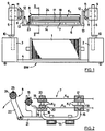
- the 1 shows a warp beam transport device BW from the side, that is to say transversely to the warp beam 1, which essentially consists of a front and a rear cuboid block 2 and 3, of a base 4 connecting these and of holding arms for the warp beam 1, not shown .
- the two blocks 2 and 3 contain, among other things, a drive for the warp beam transport device and for reloading the warp beam 1 into the weaving machine, various controls, an operating console and a hole for receiving a support column 5.
- a support platform 6 for one is on the support columns 5 Knotting frame 7 and a winding unit 8 attached.
- Trolleys 9, which are displaceable in their longitudinal direction, are mounted on the support columns 5 and are adjusted by hydraulic tappets 10 arranged in the blocks 2 and 3.
- Each trolley 9 carries on its inside rollers 11 between which a rail 12 is guided; the supporting platform 6 is fastened to the two running rails 12.
- Over the running track 12 the support platform 6 can be moved transversely to the warp beam transport device BW between a transport and a working position and fixed in these positions.
- the warp beam 1 In the working position on the weaving machine, the warp beam 1 is extended laterally on the side of the warp beam transport device BW facing the weaving machine and inserted into the bearings of the weaving machine.
- the supporting platform 6 with the assembled knotting frame 7 and the winding unit 8 is moved to the operator before inserting the warp beam.
- the warp beam 1 and the carrying platform 6 are inserted into the warp beam transport device BW in a drawer-like manner, the width of which is then determined by the diameter of the warp beam 1 and is 1.2 m in the selected example.
- the support platform 6 consists of two plate-shaped side walls 13 and a support 14 connected to it, which is preferably formed by two profile rails. To avoid any jamming or tilting when adjusting the height of the support platform 6, the connection between the support 14 and at least one of the two side walls 13 articulated. This can compensate for any tension.
- the right side wall 13 in FIG. 1 is provided with an opening through which the clamping rails of the knotting frame 7 can be pushed.
- Fig. 2 shows a cross section of the knotting frame 7 and the winding unit 8 and their attachment to the profile rails 14 forming the support of the support platform 6.
- the knotting frame 7 is formed by the upper part of a knotting frame for the USTER TOPMATIC knotting machine, and essentially consists of two pairs of clamping members K1 and K2, between which the two thread layers to be linked are stretched, from a so-called brush tree 15 to achieve a uniform warp thread tension, and from suitable carriers 16 for the clamping members and the brush tree 15.
- the clamping members K1 on the inlet side are formed by two clamps each consisting of a clamping rail 17 made of steel and a clamping strip 18 made of aluminum.
- the clamping rails 17 are known from the USTER TOPMATIC.
- the lower clamping bar 18 is provided with an additional part made of aluminum, so that the desired distance from the upper clamping bar 18 for the clamping operation can be set by lateral displacement. After the clamping operation, the distance shown is produced by a lateral displacement of the said additional part.
- the clamping members K2 on the outlet side are formed by two clamping elements, each with a clamping rail 19 and a clamping comb 20.
- the warp thread layer Kn of the new warp beam 1 is clamped between the lower clamping rail 17 and the associated clamping strip 18 on the one hand and the lower clamping rail 19 and the associated clamping comb 20 on the other hand. Then the warp beam transport device BW (FIG. 1) is driven into the weaving mill and brought into the working position, in which the warp beam 1 and of course the weaving machine are located on the right side of the knotting frame 7, based on FIG. 2.
- the old weaving warp Ka which is now to be clamped on the knotting frame 7, was also prepared by the following operations:
- the warp was pulled through the dishes over a length of about 1.5 to 2 m in the area of its end.
- the effect of the weaving harness made it possible to separate and align the individual warp threads with absolute precision.
- the old warp beam is prepared for removal by inserting a clip into the warp threads at a certain distance from the match beam and then cutting off the chain. This distance is in no way smaller than the distance between the winding unit 8 and the inlet-side clamping member K1.
- the layer of warp thread is wound around the clip and the roll thus formed is deposited on the match tree.
- the empty warp beam is removed and the BW warp beam transport device with the new warp beam can be moved to the weaving machine and the new warp beam can be inserted into the weaving machine.
- the upper terminal block 18 is placed on the lower terminal block 18, on which it is fixed by built-in magnets.
- the winding unit 8 which is used for pulling back the pulled-forward part of the old chain, essentially consists of a frame 21 screwed to the profiled rails 14, of two side parts 22 pivotably mounted in this frame, and of a side part 22 mounted therein and via a crank 23 ( Fig. 1) rotatable take-up roller 24, which carries on its circumference a thread clamp formed by a clamping strip 25, and from a brake, not shown, for the take-up roller 24.
- This brake is formed by a steel band wrapping around the take-up roller 24 and tightenable by a screw.
- the clamping strip 25 is removed from its groove on the circumference of the winding roller 24 and this is rotated so far that the groove for the clamping strip 25 is at the top as in FIG. 2.
- the operator who is in relation to FIG. 2 on the left side of the support platform 6, immediately in front of the winding unit 8, grips the role stored in the match tree and lifts them over the knotting frame 7 while simultaneously being unwound, whereby the warp thread layer Ka is placed over the winding roller 24. Then the clamping bar 25 is inserted and thereby the chain is clamped on the winding roller 24. Finally, the chain is cut off in front of the clip and then wound up on the winding roller 24 by turning the crank 23 and thereby withdrawn from the weaving machine. It may be advantageous to insert a comb into the chain before pulling back in the running direction of the warp threads when weaving in front of the warp thread monitor slats.
- the winding roller 24, together with the side parts 22 carrying it, is pivoted counterclockwise downward, to the level of the frame 21 or below it. Then, by turning the brush tree 15 counterclockwise, the thread tension is made uniform over the entire warp width and the upper clamping comb 20 is inserted and the warp threads are clamped to the upper clamping rail 19. Now the warp threads Ka between the brush tree 15 and the clamping comb mentioned are cut off and then removed from the take-up roller. The latter can be facilitated by previously inserting a clip between the brush tree 15 and take-up roller 24.
- the operations described can easily be performed by a single person. This is made possible by the fact that a clamp is used for clamping the old chain on the weaving machine instead of a bulky one-sided clamping rail, and by the winding chain using the old roller 24 is withdrawn.
- the clip is so light that it can be lifted together with the part of the old chain wound on it in front of a person over the clamping frame, and the crank drive of the winding roller, which has a suitable gear ratio, also requires only one operator.
- the method according to the invention leads to a reduction in the time required for the warp change. Since this reduction is achieved with extremely little mechanical effort, the process is also economical and leads to a noticeable increase in the efficiency.
Landscapes
- Engineering & Computer Science (AREA)
- Textile Engineering (AREA)
- Auxiliary Weaving Apparatuses, Weavers' Tools, And Shuttles (AREA)
Abstract
Claims (12)
- Procédé pour un changement de chaîne simplifié à des machines de tissage sur lesquels la partie d'extrémité d'une chaîne est tirée en avant suivant une certaine longueur, où les fils de chaîne de la chaîne terminée sont fixés par un organe en forme de rail et sont coupés et les fils de chaîne de la nouvelle chaîne sont tendus sur un cadre de nouage présentant des organes de pinçage qui est transporté à la machine de tissage, à laquelle la couche de fils de chaîne de la chaîne terminée est placée dans les organes de pinçage, caractérisé en ce que la couche de fils de chaîne (Ka) de la chaîne terminée est fixée sur un rouleau (24) associé aux organes de pinçage (K1, K2) et par une rotation de ce rouleau suivant la longueur de fil précitée, est retirée de la machine de tissage.
- Procédé selon la revendication 1, dans lequel les fils de chaîne de la chaîne terminée, après la coupe, sont enroulés pour former un rouleau, caractérisé en ce que la longueur d'enroulement est au moins aussi grande que l'écart entre le rouleau précité (24) et l'organe de pinçage (K1) plus éloigné de celui-ci.
- Procédé selon la revendication 2, caractérisé en ce qu'avant le retrait de la chaîne terminée (Ka) on place dans celle-ci dans la zone entre le cadre de nouage (7) et le casse-chaîne un peigne.
- Dispositif pour la mise en oeuvre du procédé selon la revendication 1, avec un cadre de nouage présentant des organes de pinçage pour deux couches de fils, caractérisé par un rouleau d'enroulement (24) disposé parallèlement aux organes de pinçage (K1, K2), pouvant tourner et présentant des moyens de fixation (25) pour les fils de chaîne (Ka), et par une unité de support (6) pour celui-ci et le cadre de nouage (7) qui est prévu de préférence pour le montage sur un appareil à transporter les ensouples (BW).
- Dispositif selon la revendication 4, caractérisé en ce que l'unité de support (6) est réalisée à la manière d'une plate-forme et est disposée de façon réglable en hauteur sur l'appareil à transporter les ensouples (BW).
- Dispositif selon la revendication 5, caractérisé en ce que le cadre de nouage (7) et l'unité d'enroulement (8) sont disposés de façon déplaçable dans la direction transversale de l'appareil à transporter les ensouples (BW).
- Dispositif selon la revendication 6, caractérisé par deux colonnes de support (5) pouvant être fixées sur l'appareil à transporter les ensouples (BW), sur lesquelles sont guidés des organes de retenue (9) du type à chariot pour l'unité de support (6).
- Dispositif selon la revendication 7, caractérisé en ce que l'unité de support (6) est logée de façon déplaçable aux organes de retenue (9) par des galets de roulement (11) et des rails de roulement (12) et qu'elle peut être fixée dans deux positions.
- Dispositif selon l'une des revendications 4 à 8, caractérisé en ce que les moyens de fixation du rouleau d'enroulement (24) sont constitués par une barre de pinçage (25) reliée amoviblement à ce dernier.
- Dispositif selon la revendication 9, caractérisé par un frein pour fixer le rouleau d'enroulement (24) dans des positions de rotation au choix.
- Dispositif selon la revendication 10, caractérisé en ce que le frein est constitué par un frein à tambour présentant une bande en acier entourant le rouleau d'enroulement (24).
- Dispositif selon la revendication 9, caractérisé en ce que le rouleau d'enroulement (24) est logé de façon pivotante dans un cadre (21, 22) relié solidement à l'unité de support (6).
Applications Claiming Priority (3)
| Application Number | Priority Date | Filing Date | Title |
|---|---|---|---|
| CH1273/92 | 1992-04-18 | ||
| CH01273/92A CH687541A5 (de) | 1992-04-18 | 1992-04-18 | Verfahren und Vorrichtung zum vereinfachten Kettwechsel. |
| PCT/CH1993/000100 WO1993021366A1 (fr) | 1992-04-18 | 1993-04-16 | Procede et dispositif permettant de changer plus aisement une chaine |
Publications (2)
| Publication Number | Publication Date |
|---|---|
| EP0590120A1 EP0590120A1 (fr) | 1994-04-06 |
| EP0590120B1 true EP0590120B1 (fr) | 1996-01-17 |
Family
ID=4206564
Family Applications (1)
| Application Number | Title | Priority Date | Filing Date |
|---|---|---|---|
| EP93907744A Expired - Lifetime EP0590120B1 (fr) | 1992-04-18 | 1993-04-16 | Procede et dispositif permettant de changer plus aisement une chaine |
Country Status (7)
| Country | Link |
|---|---|
| US (1) | US5430916A (fr) |
| EP (1) | EP0590120B1 (fr) |
| JP (1) | JPH06508666A (fr) |
| CH (1) | CH687541A5 (fr) |
| DE (1) | DE59301452D1 (fr) |
| ES (1) | ES2083283T3 (fr) |
| WO (1) | WO1993021366A1 (fr) |
Families Citing this family (7)
| Publication number | Priority date | Publication date | Assignee | Title |
|---|---|---|---|---|
| BE1008059A3 (nl) * | 1994-02-02 | 1996-01-03 | Picanol Nv | Werkwijze en inrichting voor het trekken op kettingdraden. |
| KR100336317B1 (ko) * | 1999-12-09 | 2002-05-13 | 김종섭 | 전동식 빔 캐리어 |
| BE1013733A3 (nl) * | 2000-10-03 | 2002-07-02 | T Sas Fran Ois | Inrichting voor het automatisch wisselen van draadvormige materialen in een draadverwerkende machine. |
| EP2662481B1 (fr) * | 2012-05-10 | 2016-03-02 | Stäubli Sargans AG | Dispositif de serrage, machine à enverjure, machine de passage et procédé de tension de plusieurs fils de chaîne |
| CN104891382B (zh) * | 2015-06-18 | 2017-03-01 | 青岛奥海纺机制造有限公司 | 一种用于辅助织布机盘头更换的装置及方法 |
| EP3771758B1 (fr) | 2019-07-31 | 2022-03-30 | Stäubli Sargans AG | Dispositif de serrage de fil et machine de préparation de tissage comprenant un tel dispositif de serrage de fil |
| CN116715170B (zh) * | 2023-07-28 | 2025-06-20 | 随州市晖宏兴布业有限责任公司 | 一种用于辅助织布机盘头更换的装置及方法 |
Family Cites Families (8)
| Publication number | Priority date | Publication date | Assignee | Title |
|---|---|---|---|---|
| CH401861A (de) * | 1963-05-20 | 1965-10-31 | Zellweger Uster Ag | Gestell zum Aufspannen von Webketten für Einziehmaschinen |
| DE1535939A1 (de) * | 1963-09-20 | 1969-10-02 | Koefoed Hauberg | Gestell mit Klemmgliedern zum Aufspannen von Webketten von deren Verknuepfen |
| CH420004A (de) * | 1965-01-14 | 1966-08-31 | Zellweger Uster Ag | Gestell zum Aufspannen von Webketten für Webkettenanknüpfmaschinen und dergleichen |
| CH432419A (de) * | 1965-12-10 | 1967-03-15 | Zellweger Uster Ag | Knüpfgestell für Webketten |
| US3696477A (en) * | 1971-05-10 | 1972-10-10 | Barber Colman Co | Warp clamp |
| CH558849A (de) * | 1973-06-28 | 1975-02-14 | Zellweger Uster Ag | Knuepfgestell mit transportwagen. |
| DE2451258A1 (de) * | 1974-10-29 | 1976-05-06 | Knotex Maschinenbau Gmbh | Fadenklemme fuer webketten-knuepfmaschinen |
| KR920702843A (ko) * | 1989-09-19 | 1992-10-28 | 데블류. 세틀레, 피. 헤르만 | 실 자동연결 장치 및 방법 |
-
1992
- 1992-04-18 CH CH01273/92A patent/CH687541A5/de not_active IP Right Cessation
-
1993
- 1993-04-16 US US08/162,191 patent/US5430916A/en not_active Expired - Fee Related
- 1993-04-16 JP JP5517887A patent/JPH06508666A/ja active Pending
- 1993-04-16 WO PCT/CH1993/000100 patent/WO1993021366A1/fr not_active Ceased
- 1993-04-16 ES ES93907744T patent/ES2083283T3/es not_active Expired - Lifetime
- 1993-04-16 DE DE59301452T patent/DE59301452D1/de not_active Expired - Fee Related
- 1993-04-16 EP EP93907744A patent/EP0590120B1/fr not_active Expired - Lifetime
Also Published As
| Publication number | Publication date |
|---|---|
| WO1993021366A1 (fr) | 1993-10-28 |
| CH687541A5 (de) | 1996-12-31 |
| ES2083283T3 (es) | 1996-04-01 |
| JPH06508666A (ja) | 1994-09-29 |
| US5430916A (en) | 1995-07-11 |
| EP0590120A1 (fr) | 1994-04-06 |
| DE59301452D1 (de) | 1996-02-29 |
Similar Documents
| Publication | Publication Date | Title |
|---|---|---|
| DE2909121C2 (de) | Eingabevorrichtung für Wäschestücke an einer Mangel | |
| DE3307301A1 (de) | Vorrichtung zur herstellung von kurzketten, insbesondere fuer gewebemuster in der buntweberei | |
| EP0368801B1 (fr) | Procédé et dispositif pour diviser les fils sur un ourdissoir | |
| DE2017325B2 (de) | Vorrichtung zur Herstellung eines nicht-gewebten offenmaschigen Netzes | |
| CH687541A5 (de) | Verfahren und Vorrichtung zum vereinfachten Kettwechsel. | |
| DE2406550A1 (de) | Verfahren zum aufbringen von reservewindungen auf eine spulenhuelse zum aufwickeln von endlosfaeden und aufwickelvorrichtung zur durchfuehrung des verfahrens | |
| EP2388362B1 (fr) | Dispositif de tension et procédé destiné à retendre des fils de chaîne d'une couche de fils de chaîne | |
| DE3016182A1 (de) | Verfahren und vorrichtung zum pneumatischen eintragen des schussfadens in die schussfadentraeger einer mehrsystemigen webmaschine | |
| EP1577429A1 (fr) | Procédé et dispositif pour le placement de rubans de fils formés par filaments | |
| DE2449138A1 (de) | Verfahren und vorrichtung zum foerdern einer vielzahl von materialstraengen entlang einem vorgegebenen foerderweg | |
| DE4132696C2 (de) | Breithalter und dessen Verwendung bei einer Webmaschine | |
| DE69026050T2 (de) | Verfahren zum Auswechseln von Vorgarnspulen in Ringspinnmaschinen | |
| DE4115059C2 (de) | Vorrichtung zum Begrenzen der Fadenballons an einem Spulengatter | |
| EP0584309B1 (fr) | Procede et dispositif pour fixer les extremites d'une couche de fils enroules sur une ensouple | |
| DE1635481B2 (de) | Maschine zur herstellung eines endlosen fadengeleges | |
| DE4033977C2 (de) | Spannvorrichtung für Kettfäden | |
| CH681901A5 (fr) | ||
| EP0826804B1 (fr) | Méthode et dispositif pour rattacher un fil dans un métier à filer à bout ouvert | |
| DE19612729A1 (de) | Vorrichtung zur Aufnahme oder Übernahme von Wickelkernen | |
| CH145944A (de) | Verfahren zur Herstellung eines Mischgarnes und Maschine zur Durchführung des Verfahrens. | |
| EP0520947B1 (fr) | Procédé et dispositif pour le maintien séparé des groupes de fils de chaîne pendant leur passage à travers une installation de teinture. | |
| EP0965668A2 (fr) | Procédé et dispositif pour transférer une nappe enroulée de fils sur une ensouple | |
| DE20113230U1 (de) | Spulenmagazin für Schussfadenvorratsspulen an Greiferwebmaschinen | |
| EP0197275A1 (fr) | Procédé et métier à tricoter chaîne rectiligne pour la fabrication d'un tricot chaîne à trames | |
| DE4100384C1 (en) | Appts. for knotting new- and old textile warps together - winds pre-determined length of warp from band spindle onto a pre-spool spindle, fixes end to empty spindle etc. |
Legal Events
| Date | Code | Title | Description |
|---|---|---|---|
| PUAI | Public reference made under article 153(3) epc to a published international application that has entered the european phase |
Free format text: ORIGINAL CODE: 0009012 |
|
| 17P | Request for examination filed |
Effective date: 19931211 |
|
| AK | Designated contracting states |
Kind code of ref document: A1 Designated state(s): BE DE ES FR GB IT PT |
|
| RAP1 | Party data changed (applicant data changed or rights of an application transferred) |
Owner name: STAEUBLI AG |
|
| 17Q | First examination report despatched |
Effective date: 19950411 |
|
| GRAA | (expected) grant |
Free format text: ORIGINAL CODE: 0009210 |
|
| AK | Designated contracting states |
Kind code of ref document: B1 Designated state(s): BE DE ES FR GB IT PT |
|
| ITF | It: translation for a ep patent filed | ||
| REF | Corresponds to: |
Ref document number: 59301452 Country of ref document: DE Date of ref document: 19960229 |
|
| GBT | Gb: translation of ep patent filed (gb section 77(6)(a)/1977) |
Effective date: 19960220 |
|
| REG | Reference to a national code |
Ref country code: ES Ref legal event code: FG2A Ref document number: 2083283 Country of ref document: ES Kind code of ref document: T3 |
|
| PG25 | Lapsed in a contracting state [announced via postgrant information from national office to epo] |
Ref country code: PT Effective date: 19960417 |
|
| ET | Fr: translation filed | ||
| PLBE | No opposition filed within time limit |
Free format text: ORIGINAL CODE: 0009261 |
|
| STAA | Information on the status of an ep patent application or granted ep patent |
Free format text: STATUS: NO OPPOSITION FILED WITHIN TIME LIMIT |
|
| 26N | No opposition filed | ||
| PGFP | Annual fee paid to national office [announced via postgrant information from national office to epo] |
Ref country code: GB Payment date: 19970407 Year of fee payment: 5 |
|
| PGFP | Annual fee paid to national office [announced via postgrant information from national office to epo] |
Ref country code: FR Payment date: 19970409 Year of fee payment: 5 |
|
| PGFP | Annual fee paid to national office [announced via postgrant information from national office to epo] |
Ref country code: DE Payment date: 19970428 Year of fee payment: 5 Ref country code: ES Payment date: 19970428 Year of fee payment: 5 |
|
| PGFP | Annual fee paid to national office [announced via postgrant information from national office to epo] |
Ref country code: BE Payment date: 19970529 Year of fee payment: 5 |
|
| PG25 | Lapsed in a contracting state [announced via postgrant information from national office to epo] |
Ref country code: GB Free format text: LAPSE BECAUSE OF NON-PAYMENT OF DUE FEES Effective date: 19980416 |
|
| PG25 | Lapsed in a contracting state [announced via postgrant information from national office to epo] |
Ref country code: ES Free format text: LAPSE BECAUSE OF EXPIRATION OF PROTECTION Effective date: 19980417 |
|
| PG25 | Lapsed in a contracting state [announced via postgrant information from national office to epo] |
Ref country code: FR Free format text: THE PATENT HAS BEEN ANNULLED BY A DECISION OF A NATIONAL AUTHORITY Effective date: 19980430 Ref country code: BE Free format text: LAPSE BECAUSE OF NON-PAYMENT OF DUE FEES Effective date: 19980430 |
|
| BERE | Be: lapsed |
Owner name: STAUBLI A.G. Effective date: 19980430 |
|
| GBPC | Gb: european patent ceased through non-payment of renewal fee |
Effective date: 19980416 |
|
| PG25 | Lapsed in a contracting state [announced via postgrant information from national office to epo] |
Ref country code: DE Free format text: LAPSE BECAUSE OF NON-PAYMENT OF DUE FEES Effective date: 19990202 |
|
| REG | Reference to a national code |
Ref country code: FR Ref legal event code: ST |
|
| REG | Reference to a national code |
Ref country code: ES Ref legal event code: FD2A Effective date: 20000601 |
|
| PG25 | Lapsed in a contracting state [announced via postgrant information from national office to epo] |
Ref country code: IT Free format text: LAPSE BECAUSE OF NON-PAYMENT OF DUE FEES Effective date: 20050416 |