EP0590731A2 - Pipettiervorrichtung und Verfahren zur Detektion der Aufnahme von Spitzen - Google Patents
Pipettiervorrichtung und Verfahren zur Detektion der Aufnahme von Spitzen Download PDFInfo
- Publication number
- EP0590731A2 EP0590731A2 EP93202783A EP93202783A EP0590731A2 EP 0590731 A2 EP0590731 A2 EP 0590731A2 EP 93202783 A EP93202783 A EP 93202783A EP 93202783 A EP93202783 A EP 93202783A EP 0590731 A2 EP0590731 A2 EP 0590731A2
- Authority
- EP
- European Patent Office
- Prior art keywords
- probe
- proboscis
- tip
- housing
- sensor
- Prior art date
- Legal status (The legal status is an assumption and is not a legal conclusion. Google has not performed a legal analysis and makes no representation as to the accuracy of the status listed.)
- Granted
Links
Images


Classifications
-
- G—PHYSICS
- G01—MEASURING; TESTING
- G01N—INVESTIGATING OR ANALYSING MATERIALS BY DETERMINING THEIR CHEMICAL OR PHYSICAL PROPERTIES
- G01N35/00—Automatic analysis not limited to methods or materials provided for in any single one of groups G01N1/00 - G01N33/00; Handling materials therefor
- G01N35/10—Devices for transferring samples or any liquids to, in, or from, the analysis apparatus, e.g. suction devices, injection devices
-
- B—PERFORMING OPERATIONS; TRANSPORTING
- B01—PHYSICAL OR CHEMICAL PROCESSES OR APPARATUS IN GENERAL
- B01L—CHEMICAL OR PHYSICAL LABORATORY APPARATUS FOR GENERAL USE
- B01L3/00—Containers or dishes for laboratory use, e.g. laboratory glassware; Droppers
- B01L3/02—Burettes; Pipettes
- B01L3/0275—Interchangeable or disposable dispensing tips
- B01L3/0279—Interchangeable or disposable dispensing tips co-operating with positive ejection means
-
- G—PHYSICS
- G01—MEASURING; TESTING
- G01N—INVESTIGATING OR ANALYSING MATERIALS BY DETERMINING THEIR CHEMICAL OR PHYSICAL PROPERTIES
- G01N35/00—Automatic analysis not limited to methods or materials provided for in any single one of groups G01N1/00 - G01N33/00; Handling materials therefor
- G01N35/10—Devices for transferring samples or any liquids to, in, or from, the analysis apparatus, e.g. suction devices, injection devices
- G01N35/1009—Characterised by arrangements for controlling the aspiration or dispense of liquids
- G01N35/1011—Control of the position or alignment of the transfer device
- G01N2035/1013—Confirming presence of tip
Definitions
- the invention relates to proboscises for use in clinical analyzers, particularly for use in a dispensing station of such analyzers where disposable tips are utilized.
- analyzers provided by Eastman Kodak Company under the trademark "Ektachem 700" have a sensor to determine when the aspirator has lowered a sufficient distance to pick up, by force-fit, a disposable tip.
- Such sensors are vertically adjusted so that, as part of the set-up calibration, the operator can adjust the trigger location of the sensor depending on that particular analyzer's margins of error.
- Other instruments have similarly adjusted sensors as described for example, in US-A-4 705 667. Once adjusted, the sensor then cooperates with a single flag for each movable part, since that flag is sufficient to trigger that the limiting condition is achieved.
- the proboscis can detect only that it has been interrupted. It is unable to determine the nature of the interfering objects since, although the proboscis may be stalled, the flag is not in position to interact with the sensor.
- a proboscis for aspirating and dispensing liquid into and out of a disposable tip provided at a tip-pickup station
- the proboscis including:- a probe having a mount surface for releasably supporting the disposable tip; a housing in which the probe is mounted; means for vertically raising and lowering the housing; and sensing means for sensing the vertical position of the probe comprising a flag and a sensor, the flag being sensed by the sensor; characterized in that the probe is supported by a d movably mounted within a base with a first spring disposed between the probe and the base; and in that a second spring is disposed between the base and the housing to allow continued movement of the housing after movement of the probe has ceased thereby generating a signal in the sensing means.
- a method for automatically determining tip pickup by a proboscis in an analyzer comprising the steps of:-
- an analyzer proboscis and tip pickup process used for aspiration are easily recalibratable when parts are replaced.
- Another advantageous feature of this invention is that the structure used to allow recalibration is also effective to automatically detect the proboscis striking objects other than a pipette tip in a tray.
- the invention is hereinafter disclosed in connection with the preferred embodiments, in which the proboscis is used in a particular analyzer, using a particular sensor and a particular drive for the proboscis.
- the invention is useful regardless of the construction of the rest of the analyzer, or the type of sensor or drive mechanism used with the proboscis, so long as the proboscis is automatically recalibratable as to the tip pickup station using a sensor fixed in place.
- Orientations such as “downwardly”, “bottom” and the like refer to orientations existing during the preferred use of the invention.
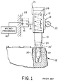
- the prior art device shown in Figure 1 comprises a proboscis featuring a probe 10 mounted within a housing 12 to which is fixed a sensing flag 14 having a single detectable station which cooperates with an adjustable sensor 16, a rack gear 18 providing up and down motion of probe 10 via pinion gear 20. Suitable bearing rail(s) 21 guide the proboscis in its motion.
- Sensor 16 is mounted on frame 22 of the analyzer and can comprise any electromagnetic radiation emitter and detector.
- Probe 10 includes a mating surface 24, which can be conical, for seating within and supporting a tip 30 supplied via tray 32. Surface 24 terminates at an end surface 25. (When probe 10 is withdrawn, tip 30 follows it out of tray 32.) Slight vertical compliance is provided between probe 10 and housing 12 by a weak spring 26 compressed within the housing by probe 10. This however is inadequate to allow for substantial changes in vertical location of trays 32 carrying tips 30.
- the calibration proceeds as follows: because the position of sensor 16 is adjustable relative to analyzer frame 22, when tray 32 and tip 30 are properly positioned, housing 12 is lowered via gear 20 until tip 30 is seated on to surface 24. Sensor 16 is then adjusted on frame 22 until flag 14 breaks the beam of the sensor, as shown by the solid line positioning of the sensor. Sensor 16 is then temporarily fixed in place. Subsequent breaking of the beam by flag 14 tells microprocessor 40 of the analyzer that tip pickup has occurred.
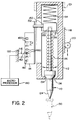
- the proboscis is improved as shown in Figures 2 and 3. Parts similar to those previously described bear the same reference numeral, to which the distinguishing prefix "1" is applied.
- Figure 2 it comprises a probe 110 movable within a housing 112 driven by a rack gear 118 and driving pinion gear 120, a mating surface 124 being provided to contact, mate, and support a tip 130 on the probe 110.
- a flag 114 operatively engages the proboscis in the manner hereinafter described, to cooperate with a sensor 116 on frame 122 of the analyzer.
- sensor 116 comprises an infrared emitter and detector, such as an Optek sensor model OP8981C11.
- a weak compression spring 126 allows some vertical compliance of probe 110 upon contact between the probe 110 and a tip 130, or a tip 130 on the probe 110 and a dispensing seat elsewhere in the analyzer.
- probe 110 It is also conventional to provide a self-seating surface 134 on probe 110 for seating within aperture 136 of housing 112, and slight angular freedom at upper end 138 of probe 110 to allow for slight angular adjustment of probe 110 out of the vertical, where necessary.
- probe 110 is carried by a base 150, which in turn is fixed to flag 114, rather than the flag being fixed to the housing 112.
- a slot 152 is provided in the housing to allow vertical movement of the flag relative to the housing.
- base 150 is movable within said housing against a relatively strong compression spring 154, a stop member 156 surrounding probe 110 to limit movement of the housing upward relative to base 150 under the expansion of spring 154.
- Spring 154 preferably provides an expansion force of about 5kg (10lbs).
- flag 114 has a plurality of signalling stations detectable by the sensor, such as cut-outs 160, and sensor 116 is fixed permanently relative to the frame 122 of the analyzer.
- Calibration can proceed by an initial machine adjustment which locates beam 162 of the sensor in a "home" position located near the bottom of flag 114.
- Probe 110 is then stepped down by half-steps, assuming the motor for driving gear 120 (not shown) is a stepper motor, until a good tip pickup is verified by the operator.
- the number of half-steps needed to do this is stored in a conventional microprocessor 140 as the "optimum" distance for tip pickup. Additionally, a tolerance factor of a certain number of half-steps is stored, this factor being chosen to represent a tip pickup location "close” to optimum. (Microprocessor 140 is preferably programmed in a conventional way.)
- the analyzer automatically determines whether good tip pickup occurs, or not, by measuring from the "home" position of probe 110, the number of half-steps before probe 110 stops moving vertically.
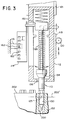
- the cessation of movement of probe 110, Figure 3 is sensed by reason of the fact that cut-outs 160 stop moving past beam 162, when flag 114 stops due to its attachment to base 150 in which probe 110 is now “bottomed out”.
- pinion 120 continues to drive housing 112 downward against spring 154, which downward overdriven movement is used to prevent jarring of the drive connection.
- a "time-out" cycle is set up in microprocessor 140 such that, when no further flag cut-out 160 is sensed by sensor 114 during the "time-out” period, probe 110 is presumed to be stopped. At this point, pinion gear 120 is also stopped, and sensor 116 and microprocessor 140 combine to generate a signal corresponding to "probe has stopped moving".
- Microprocessor 140 has of course counted the half-steps of movement between the "home" position of cut-out 160', Figure 2, and the stopped position shown in Figure 3. This is compared, for example by subtraction, by microprocessor 140 against the "optimum" number previously determined and stored, and the difference is compared with the "tolerance” factor also stored. (The "tolerance” factor is needed because of the slight vertical variation in tip seating on probe 110 due to variations in, for example, tip internal diameter tolerances.) If it is outside that factor, a "no tip” error is registered and displayed in the analyzer. For example, the distance moved will be outside that factor if probe 110 moves, in the absence of a tip, all the way into a hole 200 intended to hold a tip in tray 132.
- the distance measured will also be outside the tolerance factor if movement of the probe, and hence flag 114, has ceased because the probe strikes a foreign object. For example, an object sitting on top of tray 132 will cause the probe and flag to cease movement well before the "optimum" distance is reached.
- the use of multiple cut-outs 160 ensures that this much shorter distance of movement will also be detected using the invention.
- Another advantage of the invention is its ease in recalibration in the event of changes to the instrument. For example, replacement of parts can lead to tray 132 having its surface top 202' being located as shown in phantom. In that event, the recalibration occurs by automatic lowering of probe 110 until it makes contact with a tip in a good tip pickup (as visually confirmed by the operator), and storing that new distance moved from the "home" position shown in Figure 2, as the "optimum” distance. There is thus no need to manually readjust the physical location of sensor 116 on the frame. Instead, that sensor remains fixed relative to the analyzer.
- the microprocessor is programmed in a conventional way to carry out the processes described above.
- the flow charts of Figures 4 and 5 are illustrative of the manner in which the programming proceeds:
- the alternative of Figure 4 starts the process at step 300.
- step 302 drive gear 120 advances housing 112 so that flag 114 arrives with the middle of a cut-out 160 positioned at sensor 116 just before probe 110 enters or touches a tip 130.
- step 304 drive gear 120 advances the amount of a half-step of the stepper motor, and the microprocessor queries, step 306, if the advance has achieved the amount that is preset for a "no-tip" condition. If the answer is "yes", condition 308, then an error message of "no tip” is issued, step 310.
- step 312 is made as to whether the sensor detected during this step, the passage of cut-outs (transitions from light to dark) . If the answer is "yes”, then the iterative process is repeated back at step 304. If “no”, then a third query, step 314, is made as to whether the 1/2 pitch distance is within the tolerance distance of the "known good tip pick-up" distance. If “yes”, then the analyzer can proceed with subsequent steps, step 316. If "no”, then an error message, step 318, is issued that there is an error in the tip pickup.
- step 402 starts with the probe 110 "just above” contact with a tip, and the drive given to gear 120 is that which produces an advance of flag 114 which is less than pitch "p", Figure 2, of the cut-outs, but is greater than 1/2 p.
- step 412 A negative answer to query 306A leads to querying whether sensor 116 has failed to detect a change or not, step 412, for two consecutive advances of drive gear 120 or three consecutive reads, meaning that in fact the cut-outs are not proceeding past the sensor.
- step 414 the query is whether the distance traveled, whatever it is, is within the tolerance factor of the distance of a known "good" tip pick-up.
- the remaining stations of the analyzer can be any convenient construction. Highly preferred is the use of this invention in the dispensing station of the analyzer shown in commonly owned US-A-5 008 082.
Landscapes
- Chemical & Material Sciences (AREA)
- Health & Medical Sciences (AREA)
- General Health & Medical Sciences (AREA)
- Life Sciences & Earth Sciences (AREA)
- Analytical Chemistry (AREA)
- Biochemistry (AREA)
- Physics & Mathematics (AREA)
- General Physics & Mathematics (AREA)
- Immunology (AREA)
- Pathology (AREA)
- Clinical Laboratory Science (AREA)
- Chemical Kinetics & Catalysis (AREA)
- Automatic Analysis And Handling Materials Therefor (AREA)
Applications Claiming Priority (2)
| Application Number | Priority Date | Filing Date | Title |
|---|---|---|---|
| US07/954,632 US5273717A (en) | 1992-09-30 | 1992-09-30 | Self-calibrating analyzer aspirator |
| US954632 | 1992-09-30 |
Publications (3)
| Publication Number | Publication Date |
|---|---|
| EP0590731A2 true EP0590731A2 (de) | 1994-04-06 |
| EP0590731A3 EP0590731A3 (en) | 1994-09-28 |
| EP0590731B1 EP0590731B1 (de) | 1997-07-09 |
Family
ID=25495716
Family Applications (1)
| Application Number | Title | Priority Date | Filing Date |
|---|---|---|---|
| EP93202783A Expired - Lifetime EP0590731B1 (de) | 1992-09-30 | 1993-09-28 | Pipettiervorrichtung und Verfahren zur Detektion der Aufnahme von Spitzen |
Country Status (3)
| Country | Link |
|---|---|
| US (1) | US5273717A (de) |
| EP (1) | EP0590731B1 (de) |
| DE (1) | DE69312000T2 (de) |
Families Citing this family (21)
| Publication number | Priority date | Publication date | Assignee | Title |
|---|---|---|---|---|
| JPH11295323A (ja) * | 1998-04-13 | 1999-10-29 | Matsushita Electric Ind Co Ltd | 自動分注装置および分注方法 |
| US7452508B2 (en) * | 2000-02-22 | 2008-11-18 | Jacobs Merrit N | Aspirating and mixing of liquids within a probe tip |
| JP2002001092A (ja) * | 2000-06-22 | 2002-01-08 | Shimadzu Corp | 排液装置 |
| DE10040849A1 (de) * | 2000-08-21 | 2002-03-21 | Mwg Biotech Ag | Pipettierkopf für einen Roboter mit mehreren Pipettierspitzen |
| DE10116642C1 (de) * | 2001-04-04 | 2002-12-19 | Evotec Ag | Flüssigkeitsabgabevorrichtung |
| FR2837567B1 (fr) * | 2002-03-19 | 2005-05-06 | Romain Granger | Capteur pour machine de mesure de coordonnees tridimensionnelles |
| FI120861B (fi) * | 2002-11-08 | 2010-04-15 | Biohit Oyj | Monikanavapipetti |
| US20060246593A1 (en) * | 2003-01-03 | 2006-11-02 | Towler Gavin P | Material processing apparatus and method |
| JP4072724B2 (ja) * | 2003-04-16 | 2008-04-09 | 日立工機株式会社 | 自動分注装置 |
| US7396512B2 (en) | 2003-11-04 | 2008-07-08 | Drummond Scientific Company | Automatic precision non-contact open-loop fluid dispensing |
| US7806048B2 (en) * | 2007-04-13 | 2010-10-05 | Illinois Tool Works, Inc. | Method and apparatus for calibrating print head pressure and applying an accurate print pressure during production |
| FR2920675B1 (fr) * | 2007-09-10 | 2010-12-03 | Gilson Sas | Systeme de pipetage multicanaux comprenant un porte-pistons a guidage ameliore |
| DE202007012868U1 (de) * | 2007-09-14 | 2007-12-06 | The Gleason Works Corp. | Schlittenanordnung für eine Werkzeugmaschine |
| WO2012006084A2 (en) | 2010-06-28 | 2012-01-12 | Life Technologies Corporation | Systems and methods for transfer of liquid samples |
| CA2766735C (en) | 2011-02-07 | 2020-06-02 | Ortho-Clinical Diagnostics, Inc. | Determining conditions in centrifuged blood using measured pressure |
| EP2705929B1 (de) * | 2012-09-06 | 2021-04-14 | Siemens Healthcare Diagnostics Products GmbH | Justagesystem für ein Transfersystem in einem in vitro-Diagnostiksystem |
| CN104730269B (zh) * | 2013-12-24 | 2017-01-18 | 广州万孚生物技术股份有限公司 | 一种退tip头杠杆装置 |
| US10105708B1 (en) | 2015-04-29 | 2018-10-23 | John L. Sternick | Aspiration adapter and system |
| US10799871B1 (en) | 2015-04-29 | 2020-10-13 | John L. Sternick | Aspiration adapter and system |
| CN109540601A (zh) * | 2018-12-19 | 2019-03-29 | 孝感市森茂激光数控设备有限公司 | 一种自动沉降制片机的吸嘴缓冲机构 |
| EP4000732B1 (de) * | 2020-11-16 | 2024-10-09 | Tecan Trading Ag | Roboterarm eines automatisierten pipettiersystems |
Family Cites Families (20)
| Publication number | Priority date | Publication date | Assignee | Title |
|---|---|---|---|---|
| US3735902A (en) * | 1971-07-22 | 1973-05-29 | Instrumentation Labor Inc | Dispenser apparatus |
| US4325909A (en) * | 1980-10-24 | 1982-04-20 | Coulter Electronics, Inc. | Fluid transfer apparatus |
| US4347750A (en) * | 1980-06-16 | 1982-09-07 | Eastman Kodak Company | Potentiometric metering apparatus |
| DE3144334C2 (de) * | 1981-11-07 | 1985-06-13 | Dr. Johannes Heidenhain Gmbh, 8225 Traunreut | Wegmeßeinrichtung mit Referenzmarken |
| JPS60155942A (ja) * | 1984-01-25 | 1985-08-16 | Fuji Photo Film Co Ltd | 液体試料点着装置 |
| AT381794B (de) * | 1984-02-02 | 1986-11-25 | Avl Verbrennungskraft Messtech | Analysengeraet zur messung fluessiger oder gasfoermiger proben |
| JPH0786509B2 (ja) * | 1985-06-18 | 1995-09-20 | 株式会社東芝 | 自動化学分析装置 |
| DE3608884A1 (de) * | 1986-03-17 | 1987-09-24 | Mitec Moderne Ind Gmbh | Messanordnung |
| GB8607199D0 (en) * | 1986-03-24 | 1986-04-30 | Renishaw Plc | Position sensing probe |
| US4713974A (en) * | 1986-04-18 | 1987-12-22 | Varian Associates, Inc./Scientific Systems, Inc. | Autosampler |
| DE8613887U1 (de) * | 1986-05-22 | 1990-09-13 | Dr. Johannes Heidenhain Gmbh, 83301 Traunreut | Meßeinrichtung |
| US4824641A (en) * | 1986-06-20 | 1989-04-25 | Cetus Corporation | Carousel and tip |
| CA1285536C (en) * | 1987-03-11 | 1991-07-02 | Akihiro Ohoka | Dispensing machine |
| US4786803A (en) * | 1987-06-01 | 1988-11-22 | Hewlett-Packard Company | Single channel encoder with specific scale support structure |
| EP0311440B1 (de) * | 1987-10-09 | 1992-06-24 | Seiko Instruments Inc. | Gerät zum Durchführen einer Flüssigkeitsreaktion |
| US5008082A (en) * | 1988-08-25 | 1991-04-16 | Eastman Kodak Company | Analyzers using linear sample trays with random access |
| EP0437906A1 (de) * | 1990-01-17 | 1991-07-24 | Minoru Atake | Dosiergerät für Flüssigkeiten |
| US5052338A (en) * | 1990-01-31 | 1991-10-01 | Asymptotic Technologies, Inc. | Apparatus for dispensing viscous materials a constant height above a workpiece surface |
| DE9006138U1 (de) * | 1990-05-31 | 1990-08-02 | Dr. Johannes Heidenhain Gmbh, 8225 Traunreut | Positionsmeßeinrichtung |
| AT394446B (de) * | 1990-10-11 | 1992-03-25 | Rsf Elektronik Gmbh | Inkrementales laengenmesssystem |
-
1992
- 1992-09-30 US US07/954,632 patent/US5273717A/en not_active Expired - Lifetime
-
1993
- 1993-09-28 EP EP93202783A patent/EP0590731B1/de not_active Expired - Lifetime
- 1993-09-28 DE DE69312000T patent/DE69312000T2/de not_active Expired - Fee Related
Also Published As
| Publication number | Publication date |
|---|---|
| US5273717A (en) | 1993-12-28 |
| DE69312000T2 (de) | 1997-11-13 |
| EP0590731A3 (en) | 1994-09-28 |
| DE69312000D1 (de) | 1997-08-14 |
| EP0590731B1 (de) | 1997-07-09 |
Similar Documents
| Publication | Publication Date | Title |
|---|---|---|
| EP0590731B1 (de) | Pipettiervorrichtung und Verfahren zur Detektion der Aufnahme von Spitzen | |
| EP0482135B1 (de) | Flüssigkeitsabgabevorrichtung mit positionsgeber | |
| EP0524307B1 (de) | Kalibrierverfahren für ein automatisches analysegerät | |
| US5192506A (en) | Incubator port closure for automated assay system | |
| US6238626B1 (en) | Automatic distribution apparatus and method of distribution | |
| JP3097574B2 (ja) | 自動試料注入装置 | |
| US7314598B2 (en) | Dispenser and dispensing device | |
| US5221519A (en) | Device for scanning and centering containers filled with a liquid | |
| JPH05346433A (ja) | ピペット装置 | |
| JPH087222B2 (ja) | 自動分注希釈装置 | |
| EP0658769A1 (de) | Leckprüfungsverfahren in einer automatischen pipettiervorrichtung | |
| JP3584799B2 (ja) | 液体分注装置 | |
| JP2014119291A (ja) | 自動分析装置 | |
| AU780959B2 (en) | Fluid detection method | |
| CN100593722C (zh) | 自动分配器 | |
| JPH0599822A (ja) | 押込型硬さ試験機 | |
| JP2009501339A (ja) | 小型容器からの液体吸引を最大限にする方法および装置 | |
| JPS61275660A (ja) | サンプリング装置 | |
| JPH09257805A (ja) | 分注装置及びその良否の判定方法 | |
| JPH049734A (ja) | 液体試料分注装置 | |
| JP2662159B2 (ja) | 自動メスアップシステム | |
| JPH1048222A (ja) | ノズルチップの装着制御機構 | |
| JP2004340624A (ja) | 分注装置 | |
| JPS62235570A (ja) | 試料サンプリング装置 | |
| US20240082848A1 (en) | Automatic dispensing device |
Legal Events
| Date | Code | Title | Description |
|---|---|---|---|
| PUAI | Public reference made under article 153(3) epc to a published international application that has entered the european phase |
Free format text: ORIGINAL CODE: 0009012 |
|
| AK | Designated contracting states |
Kind code of ref document: A2 Designated state(s): BE CH DE FR GB IE IT LI LU NL |
|
| PUAL | Search report despatched |
Free format text: ORIGINAL CODE: 0009013 |
|
| AK | Designated contracting states |
Kind code of ref document: A3 Designated state(s): BE CH DE FR GB IE IT LI LU NL |
|
| 17P | Request for examination filed |
Effective date: 19941123 |
|
| RAP1 | Party data changed (applicant data changed or rights of an application transferred) |
Owner name: CLINICAL DIAGNOSTIC SYSTEMS, INC. |
|
| RAP1 | Party data changed (applicant data changed or rights of an application transferred) |
Owner name: JOHNSON & JOHNSON CLINICAL DIAGNOSTICS, INC. |
|
| GRAG | Despatch of communication of intention to grant |
Free format text: ORIGINAL CODE: EPIDOS AGRA |
|
| 17Q | First examination report despatched |
Effective date: 19961108 |
|
| GRAH | Despatch of communication of intention to grant a patent |
Free format text: ORIGINAL CODE: EPIDOS IGRA |
|
| GRAH | Despatch of communication of intention to grant a patent |
Free format text: ORIGINAL CODE: EPIDOS IGRA |
|
| GRAA | (expected) grant |
Free format text: ORIGINAL CODE: 0009210 |
|
| AK | Designated contracting states |
Kind code of ref document: B1 Designated state(s): BE CH DE FR GB IE IT LI LU NL |
|
| PG25 | Lapsed in a contracting state [announced via postgrant information from national office to epo] |
Ref country code: NL Free format text: LAPSE BECAUSE OF FAILURE TO SUBMIT A TRANSLATION OF THE DESCRIPTION OR TO PAY THE FEE WITHIN THE PRESCRIBED TIME-LIMIT Effective date: 19970709 Ref country code: LI Free format text: LAPSE BECAUSE OF FAILURE TO SUBMIT A TRANSLATION OF THE DESCRIPTION OR TO PAY THE FEE WITHIN THE PRESCRIBED TIME-LIMIT Effective date: 19970709 Ref country code: IT Free format text: LAPSE BECAUSE OF FAILURE TO SUBMIT A TRANSLATION OF THE DESCRIPTION OR TO PAY THE FEE WITHIN THE PRESCRIBED TIME-LIMIT;WARNING: LAPSES OF ITALIAN PATENTS WITH EFFECTIVE DATE BEFORE 2007 MAY HAVE OCCURRED AT ANY TIME BEFORE 2007. THE CORRECT EFFECTIVE DATE MAY BE DIFFERENT FROM THE ONE RECORDED. Effective date: 19970709 Ref country code: CH Free format text: LAPSE BECAUSE OF FAILURE TO SUBMIT A TRANSLATION OF THE DESCRIPTION OR TO PAY THE FEE WITHIN THE PRESCRIBED TIME-LIMIT Effective date: 19970709 Ref country code: BE Effective date: 19970709 |
|
| REG | Reference to a national code |
Ref country code: CH Ref legal event code: EP |
|
| REF | Corresponds to: |
Ref document number: 69312000 Country of ref document: DE Date of ref document: 19970814 |
|
| ET | Fr: translation filed | ||
| PG25 | Lapsed in a contracting state [announced via postgrant information from national office to epo] |
Ref country code: IE Free format text: LAPSE BECAUSE OF NON-PAYMENT OF DUE FEES Effective date: 19970928 |
|
| PG25 | Lapsed in a contracting state [announced via postgrant information from national office to epo] |
Ref country code: LU Free format text: LAPSE BECAUSE OF NON-PAYMENT OF DUE FEES Effective date: 19970930 |
|
| NLV1 | Nl: lapsed or annulled due to failure to fulfill the requirements of art. 29p and 29m of the patents act | ||
| REG | Reference to a national code |
Ref country code: CH Ref legal event code: PL |
|
| PLBE | No opposition filed within time limit |
Free format text: ORIGINAL CODE: 0009261 |
|
| 26N | No opposition filed | ||
| REG | Reference to a national code |
Ref country code: GB Ref legal event code: IF02 |
|
| PGFP | Annual fee paid to national office [announced via postgrant information from national office to epo] |
Ref country code: DE Payment date: 20070920 Year of fee payment: 15 |
|
| PGFP | Annual fee paid to national office [announced via postgrant information from national office to epo] |
Ref country code: GB Payment date: 20070926 Year of fee payment: 15 |
|
| PGFP | Annual fee paid to national office [announced via postgrant information from national office to epo] |
Ref country code: FR Payment date: 20070914 Year of fee payment: 15 |
|
| GBPC | Gb: european patent ceased through non-payment of renewal fee |
Effective date: 20080928 |
|
| REG | Reference to a national code |
Ref country code: FR Ref legal event code: ST Effective date: 20090529 |
|
| PG25 | Lapsed in a contracting state [announced via postgrant information from national office to epo] |
Ref country code: DE Free format text: LAPSE BECAUSE OF NON-PAYMENT OF DUE FEES Effective date: 20090401 |
|
| PG25 | Lapsed in a contracting state [announced via postgrant information from national office to epo] |
Ref country code: FR Free format text: LAPSE BECAUSE OF NON-PAYMENT OF DUE FEES Effective date: 20080930 |
|
| PG25 | Lapsed in a contracting state [announced via postgrant information from national office to epo] |
Ref country code: GB Free format text: LAPSE BECAUSE OF NON-PAYMENT OF DUE FEES Effective date: 20080928 |