EP0591619A1 - Handstück für chirurgische Operation - Google Patents
Handstück für chirurgische Operation Download PDFInfo
- Publication number
- EP0591619A1 EP0591619A1 EP93110093A EP93110093A EP0591619A1 EP 0591619 A1 EP0591619 A1 EP 0591619A1 EP 93110093 A EP93110093 A EP 93110093A EP 93110093 A EP93110093 A EP 93110093A EP 0591619 A1 EP0591619 A1 EP 0591619A1
- Authority
- EP
- European Patent Office
- Prior art keywords
- tip
- vibrator
- handpiece
- cover
- forward end
- Prior art date
- Legal status (The legal status is an assumption and is not a legal conclusion. Google has not performed a legal analysis and makes no representation as to the accuracy of the status listed.)
- Granted
Links
Images




Classifications
-
- A—HUMAN NECESSITIES
- A61—MEDICAL OR VETERINARY SCIENCE; HYGIENE
- A61B—DIAGNOSIS; SURGERY; IDENTIFICATION
- A61B17/00—Surgical instruments, devices or methods
- A61B17/32—Surgical cutting instruments
- A61B17/320068—Surgical cutting instruments using mechanical vibrations, e.g. ultrasonic
-
- A—HUMAN NECESSITIES
- A61—MEDICAL OR VETERINARY SCIENCE; HYGIENE
- A61B—DIAGNOSIS; SURGERY; IDENTIFICATION
- A61B17/00—Surgical instruments, devices or methods
- A61B17/32—Surgical cutting instruments
- A61B17/320068—Surgical cutting instruments using mechanical vibrations, e.g. ultrasonic
- A61B2017/32007—Surgical cutting instruments using mechanical vibrations, e.g. ultrasonic with suction or vacuum means
-
- A—HUMAN NECESSITIES
- A61—MEDICAL OR VETERINARY SCIENCE; HYGIENE
- A61B—DIAGNOSIS; SURGERY; IDENTIFICATION
- A61B17/00—Surgical instruments, devices or methods
- A61B17/32—Surgical cutting instruments
- A61B17/320068—Surgical cutting instruments using mechanical vibrations, e.g. ultrasonic
- A61B2017/320072—Working tips with special features, e.g. extending parts
- A61B2017/320078—Tissue manipulating surface
-
- A—HUMAN NECESSITIES
- A61—MEDICAL OR VETERINARY SCIENCE; HYGIENE
- A61B—DIAGNOSIS; SURGERY; IDENTIFICATION
- A61B17/00—Surgical instruments, devices or methods
- A61B17/32—Surgical cutting instruments
- A61B17/320068—Surgical cutting instruments using mechanical vibrations, e.g. ultrasonic
- A61B2017/320084—Irrigation sleeves
-
- A—HUMAN NECESSITIES
- A61—MEDICAL OR VETERINARY SCIENCE; HYGIENE
- A61B—DIAGNOSIS; SURGERY; IDENTIFICATION
- A61B17/00—Surgical instruments, devices or methods
- A61B17/32—Surgical cutting instruments
- A61B17/320068—Surgical cutting instruments using mechanical vibrations, e.g. ultrasonic
- A61B2017/320089—Surgical cutting instruments using mechanical vibrations, e.g. ultrasonic node location
-
- A—HUMAN NECESSITIES
- A61—MEDICAL OR VETERINARY SCIENCE; HYGIENE
- A61B—DIAGNOSIS; SURGERY; IDENTIFICATION
- A61B2218/00—Details of surgical instruments, devices or methods for transferring non-mechanical forms of energy to or from the body
- A61B2218/001—Details of surgical instruments, devices or methods for transferring non-mechanical forms of energy to or from the body having means for irrigation and/or aspiration of substances to and/or from the surgical site
- A61B2218/007—Aspiration
- A61B2218/008—Aspiration for smoke evacuation
Definitions
- the present invention relates to a handpiece for surgical operation for crushing and removing foreign bodies within a biological histology or within a coeloma or a body cavity by ultrasonic vibration or oscillation.
- a surgical operating device for crashing or cutting and separating or amputating a biological histology by ultrasonic vibration there is known a surgical operating device whose object is soft histology or tissue for ophthalmology in which lenses hardened by a cataract are crashed, drawn or sucked and removed, and for general surgery in which a tumor and a hematoma generated in brain, spine, digestive organ and the like are crashed, drawn and removed. Further, in recent years, an ultrasonic operating device is utilized which can cut and separate or isolate hard histology by ultrasonic vibration.
- the operation is such that pneumoperitoneum is made to the interior of the peritoneal cavity by carbonic acid gas or the like without ventrotomy, and a trockar is used to insert an endoscope, forceps, an electrocautery or the like into the interior of the peritoneal cavity, and extracting operation of gallbladder is performed under the field of vision of the endoscope.
- a point thereof is that a cystic duct and a cystic artery are peeled off or ablated safely and accurately from a Calot's triangle, clipping is made to the cystic duct and the cystic artery to cut the latter, and a cystic fundus is ablated from a liver bed section to grasp or grip the gallbladder by the forceps, to thereby remove the cystic fundus out of the body.
- a cystic duct 36 connected to a gallbladder 37 in a case where a cystic duct 36 connected to a gallbladder 37 is peeled off or separated, an inserting direction of a tip 100 at a forward end of a handpiece is limited or restricted by a direction of a trocar which pierces into a laparotomy from the outside of the body. Accordingly, it is difficult to separate a fundus of the cystic duct 36.
- irrigation liquid jetted from a clearance or gap between a tip cover 101 and a tip 100 by vibration of the tip 100 scatters over a wide range, resulting in that the lenses of the endoscope are clouded.
- a vibrator section such as a tip or the like which is inserted into the body is lengthened. For this reason, it is difficult to judge as to whether or not the irrigation liquid is surely or reliably supplied up to the forward end of the tip. In a case where the tip is vibrated under a condition that the irrigation liquid is insufficient, there is a fear that the irrigation liquid of high temperature is jetted so that tissues are damaged. Thus, countermeasures are required.
- the invention has an object thereof to solve the above-discussed problems of the conventional handpiece for surgical operation in which ultrasonic vibration is used, and has an object thereof to provide a handpiece for surgical operation which prevents visual field disturbance of an endoscope from occurring due to jetting of irrigation liquid in operation under narrow visual field of the endoscope, which can perform safely and correctly separation of a blood vessel or the like and which can use also a laser probe.
- a handpiece for surgical operation for crushing or cutting and separating to remove a biological histology or foreign bodies within a body cavity by ultrasonic vibration characterized by comprising a source of ultrasonic vibration, a vibrator having a joint section and a tip section reduced in diameter, the vibrator being connected to the source of ultrasonic vibration for transmitting and enlarging mechanical vibration of ultrasonic frequency, and a cover made of heat-resistant resin for receiving and covering the source of ultrasonic vibration and the vibrator, wherein the source of ultrasonic vibration and the vibrator communicate with each other and are connected to each other by a suction passage which passes through the source of ultrasonic vibration, the vibrator and the cover in a lengthwise direction, wherein the cover has, in combination, a body cover for receiving the source of ultrasonic vibration and the joint section of the vibrator and a tip cover for covering the tip section, and wherein the vibrator has a forward end thereof of the tip section which is curved in arcuate configuration.
- the tip section of the vibrator is such that an entire length from a rearward end joining to the joint section to a working portion at a forward end has a value corresponding to substantially 5/4 times or 7/4 times the wavelength, that a curvature point of the forward end of the tip section is located at a position equal to or more than 3/100 wavelength from the forward end of the tip section and within 30 mm, that a curvature angle thereof is equal to or smaller than 35°, that the forward end of the tip cover is one on which a tip top cover is mounted which is so formed as to be detachable, and which is semi-transparent or transparent, and that a forward end surface of the tip cover (the forward end surface at the time the tip top cover is mounted) has an angle with respect to an axis of the vibrator in a lengthwise direction.
- a handpiece for surgical operation characterized in that the tip cover has a main cavity through which the tip section is inserted, and an auxiliary cavity provided in parallel relation to the main cavity within a side wall of the tip cover, a gas tight packing being additionally provided on a proximal portion of the tip cover.
- a handpiece for surgical operation characterized in that the forward end of the tip portion of the vibrator is curved in arcuate configuration, that the tip cover has an O-ring on an inner surface of the main cavity in the proximal end of the tip cover, the O-ring being mounted in intimate or close contact relation to an outer periphery of the vibrator at a position which is brought to a node of the ultrasonic vibration of the vibrator, and that the forward end of the tip cover is brought to an inclined or tilting surface in a direction which connects a center of the main cavity and a center of the auxiliary cavity to each other, the tip cover having a spatula-like projection at a pointed end of the inclined surface, and that the tip cover is mounted rotatably about an axis that is the tip section of the vibrator which is inserted into the main cavity.
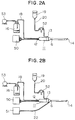
- Figs. 1A, 1B, 1C and 1D are cross-sectional views for explanation of a basic structure of a handpiece for surgical operation, according to an embodiment of the invention, while Figs. 2A and 2B are views showing an entire system which utilizes the handpiece for surgical operation, according to the invention.
- a source of ultrasonic vibration 1 is joined to a vibrator having a joint section (2) and a tip section 3, by means of screws or the like as shown in Fig. 1A.
- the joint section 2 and the tip section 3 are provided therein with a suction passage 4 which passes through the joint section 2 and the tip section 3 in a lengthwise direction.
- the joint section 2 and the tip section 3 are manufactured separately from each other as shown in Figs. 1A to 1D and 2A and 2B, and may be joined to each other by means of screws or the like. However, there is no hindrance if the joint section 2 and the tip section 3 are formed integrally.
- a cover made of heat-resistant resin for receiving and covering the above-described elements which are vibrated ultrasonically is arranged by combination of a body cover 5 for receiving the source of ultrasonic vibration 1 and the joint portion 2, and a tip cover 6 for covering a forward end of the joint portion 2 and the tip portion 3.
- the body cover 5 has a rearward end thereof which is provided therein with an opening at which a suction nipple 12 is additionally provided on a rearward end of the suction passage 4, and an opening for a cable for supplying high-frequency electric power to the source of ultrasonic vibration 1 from an ultrasonic oscillator 50.
- the tip cover 6 has an inner cavity 7 through which the tip portion 3 is inserted.
- the tip cover 6 When the tip portion 3 is inserted into the inner cavity 7, an annular space generated between the inner cavity 7 and the tip portion 3 is utilized as a passage for supplying irrigation liquid such as physiological saline solution or the like.
- the tip cover 6 has a proximal end thereof which is provided with an irrigation bore 15 which serves as an inlet for irrigation liquid.
- a using method of the handpiece 11 for surgical operation according to the invention is as follows: First, as shown in Figs. 2A and 2B, the high frequency electric power of resonant frequency is supplied to the source for ultrasonic vibration 1 within the handpiece 11, from the ultrasonic oscillator 50, to generate ultrasonic vibration thereat.
- the ultrasonic vibration is transmitted and enlarged by the vibrator in which the joint section 2 and the tip section 3 are combined with each other.
- crushing or fragmentation operation of biological histology or the like is performed.
- a roller pump 52 operates so that the irrigation liquid is injected into the tip cover 6 from a bottle 19 through an irrigation tube 20 and an irrigation nipple 13.
- the irrigation liquid passes through an annular passage between the inner wall of the inner cavity 7 and the tip section 3, and is jetted toward the working portion 14 from the forward end of the tip cover, by the ultrasonic vibration.
- the biological histology or the like is crushed or fragmented and emulsified by the ultrasonic vibration of the irrigation liquid and the working portion 14.
- Emulsified crushed pieces pass through the suction nipple 12 and a suction tube 18 through the tip section 3, the joint section 2 and the suction passage 4 within the source of ultrasonic vibration 1, by suction pressure of a suction pump 53, and are collected at a suction bottle 16.
- smoke which is generated within an abdomen cavity when the laser surgical knife and electricity are used together can be exhausted to the outside of the body through the suction passage 4 within the handpiece. Accordingly, it is possible to reduce or lighten the visual field disturbance due to the smoke.
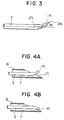
- the tip cover 6 may include a tip top cover 6 which is mounted thereon as a separate demontable part and formed of a semi-transparent or transparent material, as shown in Fig. C.
- a tip top cover 6 which is mounted thereon as a separate demontable part and formed of a semi-transparent or transparent material, as shown in Fig. C.
- the tip top cover 8 is semi-transparent or transparent, it is possible for an operator who looks or sees an endoscope image to confirm or affirm, by himself, the supply state of affairs or supply circumstances of the irrigation liquid into the tip top cover 8.
- the whole tip cover 6 may be formed by a semi-transparent or transparent material.
- the forward end of the tip cover 6 or the tip top cover 8 is brought to an inclined surface having an angle of 10 !A80 degrees with respect to the axis in the lengthwise direction and, more preferably, 45 - 60 degrees.
- the handpiece for surgical operation is used such that the handpiece is inserted into the peritoneal cavity together with the endoscope or the like, through the trocar which is arranged through the abdomen wall.
- 220 - 270 mm is required as the length of the tip section 3 having a reduced or fine diameter.
- the jointing portion between the joint section 2 and the tip section 3 is required to be provided in the vicinity of a node surface of the ultrasonic vibration in consideration of a problem such as fatigue and breakage of a material due to vibration.
- the working portion 14 at the forward end of the tip section is brought to an antinode surface of the vibration in view of the necessity that an amplitude is maximized.
- the wavelength of the ultrasonic vibration is determined or decided depending upon frequency of vibration, a material (density) of the vibrator, dimension or size of an outer diameter of the vibrator, and the like.
- the wavelength at the time frequency is 24 KHz is about 211 mm, and at 38 KHz, the wavelength is about 133 mm. Synthesizing these conditions, it is adequate that the length of the tip section of the handpiece is brought to a length corresponding to substantially 5/4 times the wavelength or 7/4 times the same.
- a curvature point 25 from which the forward end starts to be curved from the lengthwise axis is a position spaced equal to or more than 3/100 wavelength away from the forward end of the tip section.
- the curvature point 25 is within 30 mm.
- a curvature angle R which is formed by a tangent 26 with respect to the longitudinal or lengthwise axis at the forward end of the curved tip portion is equal to or less than 35 degrees. If the curvature angle R is equal to or more than 35 degrees, the effects with respect to the amplitude are reduced, and this is not preferable also from the point of view of operability of the working portion 14.
- the opening of the suction passage at the forward end of the working portion 14 is smaller than the diameter of the suction passage 4 within the tip portion 3.
- an auxiliary cavity 10 is provided within the side wall of the tip cover in parallel to the main cavity 7 through which the tip section 3 of the tip cover 6 is inserted, whereby an applied scope or range of the handpiece according to the invention is further widened.
- the proximal end of the auxiliary cavity 10 is additionally provided with a gas-tight packing 9 for holding or retaining gas tightness at the time a tube, a wire or the like is inserted into the auxiliary cavity 10.
- a probe such as a laser surgical knife, an electro surgical knife and the like into the auxiliary cavity 10 in the tip cover 6, as occasion demands.
- a laser probe 22 connected to a laser oscillator 51 is inserted into the auxiliary cavity 10 through the gas-tight packing 9 provided at the proximal end of the tip cover 6, and a laser probe working portion 22' projects from an inclined portion 21 at the forward end of the tip cover, as shown in Figs. 5A and 5B.
- the laser probe 22 used is not particularly limited to a specific one if the laser probe 22 is superior in flexibility.
- the forward end of the tip cover 6 is made to have the inclined surface included in a direction connecting a center of the main cavity 7 and a center of the auxiliary cavity 10 to each other, and a spatula-like projection 23 is provided at a pointed end of the inclined surface.
- Orientation of the inclination of the inclined portion 21 may be either of those illustrated in Figs. 5A and 5B.
- the jetting direction of the irrigation liquid due to the ultrasonic vibration of the tip working portion 14 can be limited or restricted, and it can be prevented that the irrigation liquid is scattered to adhere to the endoscope lenses.
- the inclined portion 21 and the spatula-like projection 23 are provided, it is possible to fix the blood vessels and the like by the ultrasonic vibration and to perform hemostasis due to the laser probe 22 while the blood vessels, the biological histology and the like are retained in floating and in holding down.
- smoke generated at hemostasis due to the laser can be exhausted to the outside of body by the suction passage 4 within the handpiece, it is possible to prevent the visual field from being disturbed by the smoke.
- the gas-tight packing 9 at the proximal end of the auxiliary cavity 10 into which the laser probe 22 is inserted has a role to prevent the pneumoperitoneum gas from leaking.
- the gas-tight packing 9 is made of a rubber-like elastic material. As shown in Figs. 7A, 7B and 7C, the gas-tight packing 9 has an inserting bore 28 for the laser probe at a center of the gas-tight packing 9.
- the gas-tight packing 9 has a rearward end surface and a front end surface thereof which are provided respectively with cuts 24 and 24' so as to be intersected to each other at an angle of 45°. Even after the laser probe or the like has repeatedly been inserted and demounted, the arrangement is such that gas tightness upon the use can be held or retained. Moreover, mounting of the auxiliary cavity 10 on the proximal end can easily be fixed by fitting of a holding projection 27.
- a gas-tight closure 29 is provided at the proximal end of the auxiliary cavity 10 as shown in Figs. 8A and 8B.
- the gas-tight closure 29 is pressed down by packings 31 and 30 and a ball 32 and a spring 33 under a closed condition (Fig. 8A) so as to be capable of retaining gas tightness.
- a condition (Fig. 8B) in which the gas-tight closure 29 is open it is possible to insert the laser probe 22 or the like through a probe inserting opening 34. Under this condition, gas tightness can be retained by the gas-tight packing 9. In this manner, it is possible to prevent the pneumopertoneum gas from leaking, and it is possible to prevent visual field from being reduced and gas from losing by gas leakage.
- the proximal end of the main cavity 7 in the tip cover 6 is such that an O-ring 35 is arranged on an inner surface of the main cavity 7, and the O-ring 35 is in close or intimate contact with a position which is brought to node of the ultrasonic vibration of the joint section 2 to prevent the irrigation liquid from leaking and to prevent gas from leaking from locations except for or other than the irrigation nipple 13 under a condition that the irrigation liquid is not supplied.
- gas tightness is maintained or kept by a rotor of the roller pump 21 in the irrigation tube 20 to prevent pneumoperitoneum gas within the abdomen cavity from leaking from the main cavity 7.
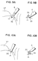
- FIGs. 9A and 9B and 10A and 10B are views showing using examples of the handpiece for surgical operation, according to the invention.
- Figs. 9A and 9B show a condition in which a lower portion of a cystic duct 36 connected to a gallbladder 37 is peeled off or separated by the working portion 14 at the forward end of the arcuate tip section, while Figs.
- 10A and 10B show a condition in which the handpiece is passed from one hand to the other at the opposite side of the cystic duct 36 to rotate the tip section 3, to thereby change orientation of the working portion 14 without the handpiece being once pulled out and reinserted from another piercing bore without the inserting portion changed, whereby peeling or separation working is made possible, and it is possible to prevent the irrigation liquid from scattering to the endoscope lenses by the inclined portion 21 and the spatula-like projection 23.
- the tip cover 6 is so formed as to be rotated about the axis of the vibrator in the lengthwise direction at junction or a connecting portion of the body cover 5, to perform positioning and fixing.
- the tip cover 6 is rotated in accordance with the state of affair or circumstances of an operating portion during operation to change orientation of the surface of the inclined portion 21 at the forward end to adjust the jetting direction of the irrigation liquid.
- affection or influence to the visual field of the endoscope due to scattering of the irrigation liquid is avoided to proceed operation more smoothly.
- the handpiece for surgical operation which utilizes the ultrasonic vibration, it is possible to accurately and safely perform identification for blood vessels or the like, it is possible to perform hemostasis by the use of the laser surgical knife or the like upon bleeding, and it is possible also to prevent the endoscope lenses from clouding due to scattering of the irrigation liquid. Not only it is possible to perform operation smoothly, but also an attempt is made to enlarge applied cases.
- the handpiece for surgical operation is useful as a handpiece for surgical operation.
Landscapes
- Health & Medical Sciences (AREA)
- Surgery (AREA)
- Engineering & Computer Science (AREA)
- Life Sciences & Earth Sciences (AREA)
- Heart & Thoracic Surgery (AREA)
- Nuclear Medicine, Radiotherapy & Molecular Imaging (AREA)
- Mechanical Engineering (AREA)
- Biomedical Technology (AREA)
- Dentistry (AREA)
- Medical Informatics (AREA)
- Molecular Biology (AREA)
- Animal Behavior & Ethology (AREA)
- General Health & Medical Sciences (AREA)
- Public Health (AREA)
- Veterinary Medicine (AREA)
- Surgical Instruments (AREA)
- Endoscopes (AREA)
Applications Claiming Priority (2)
| Application Number | Priority Date | Filing Date | Title |
|---|---|---|---|
| JP268859/92 | 1992-10-07 | ||
| JP4268859A JP2911689B2 (ja) | 1992-10-07 | 1992-10-07 | 外科手術用ハンドピース |
Publications (2)
| Publication Number | Publication Date |
|---|---|
| EP0591619A1 true EP0591619A1 (de) | 1994-04-13 |
| EP0591619B1 EP0591619B1 (de) | 1996-11-13 |
Family
ID=17464263
Family Applications (1)
| Application Number | Title | Priority Date | Filing Date |
|---|---|---|---|
| EP93110093A Expired - Lifetime EP0591619B1 (de) | 1992-10-07 | 1993-06-24 | Handstück für chirurgische Operation |
Country Status (8)
| Country | Link |
|---|---|
| US (1) | US5346469A (de) |
| EP (1) | EP0591619B1 (de) |
| JP (1) | JP2911689B2 (de) |
| AU (1) | AU664279B2 (de) |
| CA (1) | CA2099077C (de) |
| DE (1) | DE69305956T2 (de) |
| DK (1) | DK0591619T3 (de) |
| ES (1) | ES2094417T3 (de) |
Cited By (4)
| Publication number | Priority date | Publication date | Assignee | Title |
|---|---|---|---|---|
| DE19718708A1 (de) * | 1997-05-02 | 1998-11-05 | Gunther Dr Burgard | Hämorrhoidenresektionsinstrument |
| US6436114B1 (en) * | 1998-02-18 | 2002-08-20 | Storz Endoskop Gmbh | Apparatus for treating body tissue with ultrasound |
| EP1396232A1 (de) * | 2002-09-09 | 2004-03-10 | Berchtold Holding GmbH | Ultraschallinstrument |
| EP2135569A2 (de) | 2008-06-19 | 2009-12-23 | Olympus Medical Systems Corporation | Chirurgisches Ultraschallinstrument |
Families Citing this family (20)
| Publication number | Priority date | Publication date | Assignee | Title |
|---|---|---|---|---|
| US5554155A (en) * | 1994-06-03 | 1996-09-10 | Johns Hopkins University | Fiber optic pick manipulator |
| US5827229A (en) * | 1995-05-24 | 1998-10-27 | Boston Scientific Corporation Northwest Technology Center, Inc. | Percutaneous aspiration thrombectomy catheter system |
| US5938645A (en) * | 1995-05-24 | 1999-08-17 | Boston Scientific Corporation Northwest Technology Center Inc. | Percutaneous aspiration catheter system |
| US6256859B1 (en) | 1998-09-25 | 2001-07-10 | Sherwood Services Ag | Method of manufacturing an aspiring tool |
| US6139554A (en) * | 1999-06-10 | 2000-10-31 | Karkar; Maurice N. | Multipurpose tissue resurfacing handpiece |
| US6692474B1 (en) | 1999-07-19 | 2004-02-17 | Sumitomo Bakelite Co., Ltd. | Recovery instrument |
| US6401066B1 (en) * | 1999-11-09 | 2002-06-04 | West Teleservices Holding Company | Automated third party verification system |
| US20040127926A1 (en) * | 2002-09-24 | 2004-07-01 | Beaupre Jean M. | Ultrasonic surgical instrument having an increased working length |
| US20070060888A1 (en) * | 2005-09-06 | 2007-03-15 | Kerberos Proximal Solutions, Inc. | Methods and apparatus for assisted aspiration |
| US12133816B2 (en) | 2012-03-26 | 2024-11-05 | Johnson & Johnson Surgical Vision, Inc. | Phacoemulsification circuit |
| US11191669B2 (en) | 2012-03-26 | 2021-12-07 | Johnson & Johnson Surgical Vision, Inc. | Tapered structure in a phacoemulsification device for node placement |
| US11197778B2 (en) | 2012-03-26 | 2021-12-14 | Johnson & Johnson Surgical Vision, Inc. | Tapered structure in a phacoemulsification device for node placement |
| US9393037B2 (en) * | 2012-06-29 | 2016-07-19 | Ethicon Endo-Surgery, Llc | Surgical instruments with articulating shafts |
| USD704024S1 (en) * | 2012-07-10 | 2014-05-06 | 3M Innovative Properties Company | Handle |
| USD704025S1 (en) * | 2012-11-21 | 2014-05-06 | 3M Innovative Properties Company | Handle |
| RU2616215C1 (ru) * | 2016-01-28 | 2017-04-13 | Федеральное государственное автономное учреждение "Межотраслевой научно-технический комплекс "Микрохирургия глаза" имени академика С.Н. Федорова" Министерства здравоохранения Российской Федерации | Шпатель для расслаивания роговичных разрезов и парацентезов, выполненных с помощью лазерной энергии при факоэмульсификации катаракты с фемтосекундным сопровождением |
| US11596726B2 (en) * | 2016-12-17 | 2023-03-07 | C.R. Bard, Inc. | Ultrasound devices for removing clots from catheters and related methods |
| WO2019134206A1 (zh) * | 2018-01-29 | 2019-07-11 | 北京水木天蓬医疗技术有限公司 | 一种微创超声刀头及微创超声骨动力系统 |
| CN110755117A (zh) * | 2019-10-22 | 2020-02-07 | 重庆博仕康科技有限公司 | 剥离子吸引器 |
| CN110786927A (zh) * | 2019-12-06 | 2020-02-14 | 哈尔滨海鸿基业科技发展有限公司 | 手术电刀血管识别预警装置 |
Citations (5)
| Publication number | Priority date | Publication date | Assignee | Title |
|---|---|---|---|---|
| US4178935A (en) * | 1977-07-21 | 1979-12-18 | Ediny Jury G | Method and apparatus for disintegration of urinary concretions |
| DE3707567A1 (de) * | 1986-03-10 | 1987-09-17 | Olympus Optical Co | Ultraschall-behandlungsgeraet |
| DE4040537A1 (de) * | 1990-02-02 | 1991-08-08 | Olympus Optical Co | Ultraschallvorrichtung |
| EP0443256A1 (de) * | 1990-01-23 | 1991-08-28 | Urcan Medical Limited | Ultraschall-Rekanalisierungssystem |
| EP0482847A1 (de) * | 1990-10-26 | 1992-04-29 | Alcon Surgical, Inc., | Verfahren und Vorrichtung zum selektiven Entfernen von lebendem Gewebe |
Family Cites Families (10)
| Publication number | Priority date | Publication date | Assignee | Title |
|---|---|---|---|---|
| US4922902A (en) * | 1986-05-19 | 1990-05-08 | Valleylab, Inc. | Method for removing cellular material with endoscopic ultrasonic aspirator |
| US5015227A (en) * | 1987-09-30 | 1991-05-14 | Valleylab Inc. | Apparatus for providing enhanced tissue fragmentation and/or hemostasis |
| US5002557A (en) * | 1989-04-06 | 1991-03-26 | Hasson Harrith M | Laparoscopic cannula |
| US5255669A (en) * | 1989-04-12 | 1993-10-26 | Olympus Optical Co., Ltd. | Ultrasonic treatment apparatus |
| US5180363A (en) * | 1989-04-27 | 1993-01-19 | Sumitomo Bakelite Company Company Limited | Operation device |
| CA2042006C (en) * | 1990-05-11 | 1995-08-29 | Morito Idemoto | Surgical ultrasonic horn |
| DE69024805T2 (de) * | 1990-05-17 | 1996-05-23 | Sumitomo Bakelite Co | Chirurgisches instrument |
| WO1992010139A1 (en) * | 1990-12-14 | 1992-06-25 | Kelman Charles D | Tissue scraper element for medical use |
| US5207917A (en) * | 1991-10-08 | 1993-05-04 | Weaver Thomas J M | Recycling and recovery of aqueous cleaner solutions |
| US5242385A (en) * | 1991-10-08 | 1993-09-07 | Surgical Design Corporation | Ultrasonic handpiece |
-
1992
- 1992-10-07 JP JP4268859A patent/JP2911689B2/ja not_active Expired - Fee Related
-
1993
- 1993-06-21 AU AU41410/93A patent/AU664279B2/en not_active Ceased
- 1993-06-23 CA CA002099077A patent/CA2099077C/en not_active Expired - Fee Related
- 1993-06-24 ES ES93110093T patent/ES2094417T3/es not_active Expired - Lifetime
- 1993-06-24 DK DK93110093.7T patent/DK0591619T3/da active
- 1993-06-24 EP EP93110093A patent/EP0591619B1/de not_active Expired - Lifetime
- 1993-06-24 DE DE69305956T patent/DE69305956T2/de not_active Expired - Fee Related
- 1993-06-25 US US08/085,771 patent/US5346469A/en not_active Expired - Fee Related
Patent Citations (5)
| Publication number | Priority date | Publication date | Assignee | Title |
|---|---|---|---|---|
| US4178935A (en) * | 1977-07-21 | 1979-12-18 | Ediny Jury G | Method and apparatus for disintegration of urinary concretions |
| DE3707567A1 (de) * | 1986-03-10 | 1987-09-17 | Olympus Optical Co | Ultraschall-behandlungsgeraet |
| EP0443256A1 (de) * | 1990-01-23 | 1991-08-28 | Urcan Medical Limited | Ultraschall-Rekanalisierungssystem |
| DE4040537A1 (de) * | 1990-02-02 | 1991-08-08 | Olympus Optical Co | Ultraschallvorrichtung |
| EP0482847A1 (de) * | 1990-10-26 | 1992-04-29 | Alcon Surgical, Inc., | Verfahren und Vorrichtung zum selektiven Entfernen von lebendem Gewebe |
Cited By (8)
| Publication number | Priority date | Publication date | Assignee | Title |
|---|---|---|---|---|
| DE19718708A1 (de) * | 1997-05-02 | 1998-11-05 | Gunther Dr Burgard | Hämorrhoidenresektionsinstrument |
| WO1998049950A1 (de) | 1997-05-02 | 1998-11-12 | Gunther Burgard | Hämorrhoidenresektionsinstrument |
| DE19718708C2 (de) * | 1997-05-02 | 2002-07-18 | Gunther Burgard | Resektionsinstrument |
| US6436114B1 (en) * | 1998-02-18 | 2002-08-20 | Storz Endoskop Gmbh | Apparatus for treating body tissue with ultrasound |
| EP1396232A1 (de) * | 2002-09-09 | 2004-03-10 | Berchtold Holding GmbH | Ultraschallinstrument |
| EP2135569A2 (de) | 2008-06-19 | 2009-12-23 | Olympus Medical Systems Corporation | Chirurgisches Ultraschallinstrument |
| EP2135569A3 (de) * | 2008-06-19 | 2010-01-06 | Olympus Medical Systems Corporation | Chirurgisches Ultraschallinstrument |
| US8273087B2 (en) | 2008-06-19 | 2012-09-25 | Olympus Medical Systems Corp. | Ultrasonic surgical apparatus |
Also Published As
| Publication number | Publication date |
|---|---|
| JPH06114072A (ja) | 1994-04-26 |
| US5346469A (en) | 1994-09-13 |
| DE69305956D1 (de) | 1996-12-19 |
| ES2094417T3 (es) | 1997-01-16 |
| EP0591619B1 (de) | 1996-11-13 |
| DE69305956T2 (de) | 1997-04-10 |
| AU4141093A (en) | 1994-04-21 |
| CA2099077A1 (en) | 1994-04-08 |
| DK0591619T3 (da) | 1997-04-21 |
| CA2099077C (en) | 1998-06-16 |
| JP2911689B2 (ja) | 1999-06-23 |
| AU664279B2 (en) | 1995-11-09 |
Similar Documents
| Publication | Publication Date | Title |
|---|---|---|
| US5346469A (en) | Handpiece for surgical operation | |
| US5085658A (en) | Neurosurgical pathological tissue removing device | |
| JPS6136255Y2 (de) | ||
| US6669690B1 (en) | Ultrasound treatment system | |
| JPS62224341A (ja) | 生体組織の凍結破砕装置 | |
| JPH09140722A (ja) | 超音波治療装置 | |
| JPH05168645A (ja) | アテローム性動脈硬化斑の超音波解剖・分離装置 | |
| CN101190138A (zh) | 超声波处理装置 | |
| EP3260064B1 (de) | Behandlungsvorrichtung und behandlungssystem | |
| AU2007248297A1 (en) | Multi-purpose phacoemulsification needle | |
| JPH10216146A (ja) | 超音波アダプタ | |
| US20070260144A1 (en) | Acoustic Control of Emboli in Vivo | |
| EP0919210A1 (de) | Sondenartiges Absaugegerät mit Schneidevoorichtung | |
| JPH07184908A (ja) | 組織サンプル採取管付き外科手術用具 | |
| JP2963313B2 (ja) | 外科手術用ハンドピース | |
| JPH0795985A (ja) | 外科手術用ハンドピース | |
| JP2500214B2 (ja) | 外科手術用ハンドピ―ス | |
| JPH0759789A (ja) | 外科手術用ハンドピース | |
| JPH09215747A (ja) | 超音波吸引装置 | |
| JPH04307044A (ja) | 鉗子装置 | |
| JPS61191350A (ja) | 外科手術用具 | |
| JPS61265134A (ja) | 外科用切除器具 | |
| JPH0572819B2 (de) | ||
| JPH07184909A (ja) | 治療装置 | |
| JPH05309098A (ja) | 超音波メス用保護カバー |
Legal Events
| Date | Code | Title | Description |
|---|---|---|---|
| PUAI | Public reference made under article 153(3) epc to a published international application that has entered the european phase |
Free format text: ORIGINAL CODE: 0009012 |
|
| AK | Designated contracting states |
Kind code of ref document: A1 Designated state(s): DE DK ES FR GB IT NL SE |
|
| 17P | Request for examination filed |
Effective date: 19940901 |
|
| 17Q | First examination report despatched |
Effective date: 19941129 |
|
| GRAG | Despatch of communication of intention to grant |
Free format text: ORIGINAL CODE: EPIDOS AGRA |
|
| GRAH | Despatch of communication of intention to grant a patent |
Free format text: ORIGINAL CODE: EPIDOS IGRA |
|
| GRAH | Despatch of communication of intention to grant a patent |
Free format text: ORIGINAL CODE: EPIDOS IGRA |
|
| GRAA | (expected) grant |
Free format text: ORIGINAL CODE: 0009210 |
|
| AK | Designated contracting states |
Kind code of ref document: B1 Designated state(s): DE DK ES FR GB IT NL SE |
|
| REF | Corresponds to: |
Ref document number: 69305956 Country of ref document: DE Date of ref document: 19961219 |
|
| REG | Reference to a national code |
Ref country code: ES Ref legal event code: FG2A Ref document number: 2094417 Country of ref document: ES Kind code of ref document: T3 |
|
| ITF | It: translation for a ep patent filed | ||
| ET | Fr: translation filed | ||
| ET | Fr: translation filed |
Free format text: CORRECTIONS |
|
| REG | Reference to a national code |
Ref country code: DK Ref legal event code: T3 |
|
| PLBE | No opposition filed within time limit |
Free format text: ORIGINAL CODE: 0009261 |
|
| STAA | Information on the status of an ep patent application or granted ep patent |
Free format text: STATUS: NO OPPOSITION FILED WITHIN TIME LIMIT |
|
| 26N | No opposition filed | ||
| REG | Reference to a national code |
Ref country code: GB Ref legal event code: IF02 |
|
| PGFP | Annual fee paid to national office [announced via postgrant information from national office to epo] |
Ref country code: NL Payment date: 20030429 Year of fee payment: 11 |
|
| PGFP | Annual fee paid to national office [announced via postgrant information from national office to epo] |
Ref country code: ES Payment date: 20030602 Year of fee payment: 11 |
|
| PGFP | Annual fee paid to national office [announced via postgrant information from national office to epo] |
Ref country code: SE Payment date: 20030604 Year of fee payment: 11 |
|
| PGFP | Annual fee paid to national office [announced via postgrant information from national office to epo] |
Ref country code: DK Payment date: 20030613 Year of fee payment: 11 |
|
| PGFP | Annual fee paid to national office [announced via postgrant information from national office to epo] |
Ref country code: FR Payment date: 20030616 Year of fee payment: 11 |
|
| PGFP | Annual fee paid to national office [announced via postgrant information from national office to epo] |
Ref country code: GB Payment date: 20030618 Year of fee payment: 11 |
|
| PGFP | Annual fee paid to national office [announced via postgrant information from national office to epo] |
Ref country code: DE Payment date: 20030624 Year of fee payment: 11 |
|
| PG25 | Lapsed in a contracting state [announced via postgrant information from national office to epo] |
Ref country code: GB Free format text: LAPSE BECAUSE OF NON-PAYMENT OF DUE FEES Effective date: 20040624 |
|
| PG25 | Lapsed in a contracting state [announced via postgrant information from national office to epo] |
Ref country code: SE Free format text: LAPSE BECAUSE OF NON-PAYMENT OF DUE FEES Effective date: 20040625 Ref country code: ES Free format text: LAPSE BECAUSE OF NON-PAYMENT OF DUE FEES Effective date: 20040625 |
|
| PG25 | Lapsed in a contracting state [announced via postgrant information from national office to epo] |
Ref country code: DK Free format text: LAPSE BECAUSE OF NON-PAYMENT OF DUE FEES Effective date: 20040630 |
|
| PG25 | Lapsed in a contracting state [announced via postgrant information from national office to epo] |
Ref country code: NL Free format text: LAPSE BECAUSE OF NON-PAYMENT OF DUE FEES Effective date: 20050101 Ref country code: DE Free format text: LAPSE BECAUSE OF NON-PAYMENT OF DUE FEES Effective date: 20050101 |
|
| REG | Reference to a national code |
Ref country code: DK Ref legal event code: EBP |
|
| EUG | Se: european patent has lapsed | ||
| EUG | Se: european patent has lapsed | ||
| GBPC | Gb: european patent ceased through non-payment of renewal fee |
Effective date: 20040624 |
|
| PG25 | Lapsed in a contracting state [announced via postgrant information from national office to epo] |
Ref country code: FR Free format text: LAPSE BECAUSE OF NON-PAYMENT OF DUE FEES Effective date: 20050228 |
|
| NLV4 | Nl: lapsed or anulled due to non-payment of the annual fee |
Effective date: 20050101 |
|
| REG | Reference to a national code |
Ref country code: FR Ref legal event code: ST |
|
| PG25 | Lapsed in a contracting state [announced via postgrant information from national office to epo] |
Ref country code: IT Free format text: LAPSE BECAUSE OF NON-PAYMENT OF DUE FEES;WARNING: LAPSES OF ITALIAN PATENTS WITH EFFECTIVE DATE BEFORE 2007 MAY HAVE OCCURRED AT ANY TIME BEFORE 2007. THE CORRECT EFFECTIVE DATE MAY BE DIFFERENT FROM THE ONE RECORDED. Effective date: 20050624 |
|
| REG | Reference to a national code |
Ref country code: ES Ref legal event code: FD2A Effective date: 20040625 |