EP0591693B1 - Système pour le rainurage et le laminage de corps linéaires et tubes plats pour échangeur de chaleur en résultant - Google Patents
Système pour le rainurage et le laminage de corps linéaires et tubes plats pour échangeur de chaleur en résultant Download PDFInfo
- Publication number
- EP0591693B1 EP0591693B1 EP93114427A EP93114427A EP0591693B1 EP 0591693 B1 EP0591693 B1 EP 0591693B1 EP 93114427 A EP93114427 A EP 93114427A EP 93114427 A EP93114427 A EP 93114427A EP 0591693 B1 EP0591693 B1 EP 0591693B1
- Authority
- EP
- European Patent Office
- Prior art keywords
- roll
- sheet metal
- grooving
- groove forming
- heat exchanger
- Prior art date
- Legal status (The legal status is an assumption and is not a legal conclusion. Google has not performed a legal analysis and makes no representation as to the accuracy of the status listed.)
- Expired - Lifetime
Links
Images


Classifications
-
- B—PERFORMING OPERATIONS; TRANSPORTING
- B21—MECHANICAL METAL-WORKING WITHOUT ESSENTIALLY REMOVING MATERIAL; PUNCHING METAL
- B21C—MANUFACTURE OF METAL SHEETS, WIRE, RODS, TUBES, PROFILES OR LIKE SEMI-MANUFACTURED PRODUCTS OTHERWISE THAN BY ROLLING; AUXILIARY OPERATIONS USED IN CONNECTION WITH METAL-WORKING WITHOUT ESSENTIALLY REMOVING MATERIAL
- B21C37/00—Manufacture of metal sheets, rods, wire, tubes, profiles or like semi-manufactured products, not otherwise provided for; Manufacture of tubes of special shape
- B21C37/06—Manufacture of metal sheets, rods, wire, tubes, profiles or like semi-manufactured products, not otherwise provided for; Manufacture of tubes of special shape of tubes or metal hoses; Combined procedures for making tubes, e.g. for making multi-wall tubes
- B21C37/15—Making tubes of special shape; Making tube fittings
- B21C37/151—Making tubes with multiple passages
-
- B—PERFORMING OPERATIONS; TRANSPORTING
- B21—MECHANICAL METAL-WORKING WITHOUT ESSENTIALLY REMOVING MATERIAL; PUNCHING METAL
- B21C—MANUFACTURE OF METAL SHEETS, WIRE, RODS, TUBES, PROFILES OR LIKE SEMI-MANUFACTURED PRODUCTS OTHERWISE THAN BY ROLLING; AUXILIARY OPERATIONS USED IN CONNECTION WITH METAL-WORKING WITHOUT ESSENTIALLY REMOVING MATERIAL
- B21C37/00—Manufacture of metal sheets, rods, wire, tubes, profiles or like semi-manufactured products, not otherwise provided for; Manufacture of tubes of special shape
- B21C37/06—Manufacture of metal sheets, rods, wire, tubes, profiles or like semi-manufactured products, not otherwise provided for; Manufacture of tubes of special shape of tubes or metal hoses; Combined procedures for making tubes, e.g. for making multi-wall tubes
- B21C37/15—Making tubes of special shape; Making tube fittings
- B21C37/20—Making helical or similar guides in or on tubes without removing material, e.g. by drawing same over mandrels, by pushing same through dies ; Making tubes with angled walls, ribbed tubes or tubes with decorated walls
- B21C37/202—Making helical or similar guides in or on tubes without removing material, e.g. by drawing same over mandrels, by pushing same through dies ; Making tubes with angled walls, ribbed tubes or tubes with decorated walls with guides parallel to the tube axis
-
- F—MECHANICAL ENGINEERING; LIGHTING; HEATING; WEAPONS; BLASTING
- F28—HEAT EXCHANGE IN GENERAL
- F28F—DETAILS OF HEAT-EXCHANGE AND HEAT-TRANSFER APPARATUS, OF GENERAL APPLICATION
- F28F1/00—Tubular elements; Assemblies of tubular elements
- F28F1/10—Tubular elements and assemblies thereof with means for increasing heat-transfer area, e.g. with fins, with projections, with recesses
- F28F1/40—Tubular elements and assemblies thereof with means for increasing heat-transfer area, e.g. with fins, with projections, with recesses the means being only inside the tubular element
-
- F—MECHANICAL ENGINEERING; LIGHTING; HEATING; WEAPONS; BLASTING
- F28—HEAT EXCHANGE IN GENERAL
- F28F—DETAILS OF HEAT-EXCHANGE AND HEAT-TRANSFER APPARATUS, OF GENERAL APPLICATION
- F28F3/00—Plate-like or laminated elements; Assemblies of plate-like or laminated elements
- F28F3/02—Elements or assemblies thereof with means for increasing heat-transfer area, e.g. with fins, with recesses, with corrugations
- F28F3/025—Elements or assemblies thereof with means for increasing heat-transfer area, e.g. with fins, with recesses, with corrugations the means being corrugated, plate-like elements
Definitions
- the present invention relates generally to a system for grooving and rolling a sheet metal according to the preamble of claim 1, as it is known from JP-A-4 157 017, and more particularly to the same used in a pre-welding process upon manufacture of a heat exchanger tube with grooved inner surface for a heat exchanger for an air conditioner, and a flat heat exchanger tube resulting therefrom.
- An air conditioner for domestic use has been reduced in size to make a living space comfortable.
- the reduction in size of the air conditioner is obtained by decreasing the entirety of component parts.
- the air conditioner has a heat exchanger part which occupies a large part therein, and includes a heat exchanger tube through which heating medium passes, the heat exchanger tube being made of copper with excellent heat conductivity, and having an inner surface with grooves formed, for example, in a spiral, so as to largely improve the efficiency.
- a billet is subjected to extrusion, rolling, and drawing in turn, then grooved, obtaining a seamless copper tube.
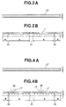
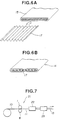
- a method as shown in Fig. 7 becomes often adopted in which an original sheet metal 10 is subjected to grooving/rolling by a grooved rolling part 21, and shaped into a tube by a tube forming part 22, a butt portion thereof being welded by a seam welding equipment 23 to obtain a welded heat exchanger tube 13.
- the method on high frequency welding enables a reduction in diameter of the copper tube as compared with the seamless method, resulting in an advantage in connection with countermeasures against a reduction in size of the heat exchanger part.
- an air conditioner for use in a motor vehicle includes a heat exchanger having harmonica tubes 25 obtained by extrusion molding of aluminum as shown in Fig. 8A, or inner fin tubes 26 each obtained by inserting a wavy fin or rib 28 into an aluminum flat tube 27 subjected to high frequency welding which are soldered as shown in Fig. 8B, and outer fins 29 superimposed alternately as shown in Fig. 8C.
- This air conditioner is used in ventilating a portion of the outer fins 29.
- the principal conditions of welding are as follows: 1) welding temperature which depends on heat input, speed, thickness, approach angle, and resistance; 2) butt which depends on parallel butt and pressure welding width which in turn depends on width, thickness, preforming, and slit shape; 3) atmosphere which depends on non-oxidation which in turn depends on Argon (Ar) gas flow.
- Control for input heat of 1) is carried out in using various fluctuation factors, and control methods for the welding temperature of 1) and the welding atmosphere of 3) are established.
- control should be carried out in processes of rolling of the sheet metal, and shaping and roll forming of slits or grooves, however, control on detected fluctuation factors cannot currently be adopted. Up to the present, it is carried out in accordance with inspection of a size of the sheet metal and a section of the slit to select nondefectives which may have a practical tolerance of accuracy or dispersion.
- the sheet metal grooved according to the actual groove shaping method has welds unstable and insufficient in strength, resulting in impossible elimination of secular dispersion.
- a heat exchanger area of the heat exchanger tube should be increased by a reduced part of heat exchanger characteristic, which produces a problem of a weight and size thereof. Therefore, performance of the heat exchanger tube should be improved to fully compensate a reduction in heat exchanger characteristic.
- an object of the present invention to provide a system for grooving and rolling a sheet metal without any dispersion of a width and end face shape thereof and with sufficient heat exchanger characteristic, and a flat heat exchanger tube resulting therefrom.
- the system for grooving and rolling a sheet metal described in the preamble of claim 1 is characterized by the features of the characterizing portion of claim 1.
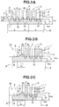
- FIG. 1A to 2B there is shown a first preferred embodiment wherein reference numerals 1 and 8 designate a groove forming roll and a support roll, respectively, in a system for grooving and rolling a sheet metal.
- 10 designates an original sheet metal
- 11 designates a sheet metal rolled and grooved.
- the groove forming roll 1 comprises a groove forming part 1A, and edge rolling parts 1B disposed on both ends thereof.
- the groove forming part 1A is provided with a plurality of grooving protrusions 2 with a pitch p, a height h 2 and an inclination angle ⁇ , and a section formed substantially in a trapezoid, and a lower protrusion 3 located in the center of the groove forming part 1A for contacting a surface of the original sheet metal upon grooving/rolling.
- each edge rolling part 1B comprises a small diameter portion 7 connected to a base portion of the grooving protrusion 2' disposed at an end of the groove forming part 1A, and an end rolling part 5 having a bevel portion.
- a width w 2 of the small diameter portion 7 is larger than a width w 1 of a groove portion 4 of the groove forming part 1A.
- the support roll 8 is provided with flanges 9 at both ends thereof for arresting elongation of the sheet metal in the cross direction thereof upon grooving/rolling.
- a height of the flange 9 is determined so that when the flange 9 comes in contact with the end rolling part 5 of the groove forming roll 1, a distance between the grooving protrusion 2' of the groove forming part 1A and a surface of the support roll 8 is equal to a predetermined thickness t min of each groove 12 of the sheet metal 11 grooved and rolled.
- the width w 2 of the small diameter portion 7' connected to the base portion of the grooving protrusion 2' of the edge rolling part 1B is not equal to the width w 1 of the groove portion 4 of the groove forming part 1A, while a diameter of the small diameter portion 7' is smaller than a diameter of the groove portion 4.
- the groove forming roll 1 and the support roll 8 are disposed so that the flanges 9 of the support roll 8 contact the end rolling part 5 of the groove forming roll 1 constructed as described above, which are rotated so that the original sheet metal 10 as shown in Fig. 2A passes therebetween for grooving/rolling.
- each grooving protrusion 2 of the groove forming part 1A presses the surface of the original sheet metal 10 to obtain the thickness t min , thus forming the groove 12.
- a portion of the sheet metal extruded from the groove 12 by the grooving protrusion 2 serves to come in the groove portion 4 of the groove forming roll 1 in increasing a thickness of an adjacent portion thereof, forming a protrusion portion with a thickness t max .
- a portion of the sheet metal metal which could not come in the groove portion 4 due to a greater thickness t 0 of the sheet metal than a reference value, etc. moves in the cross direction of the sheet metal so as to come in a clearance g 1 which is formed on both sides of the lower protrusion 3 disposed in the center of the groove forming roll 1.
- the clearance g 1 serves as a buffer area C 1 for alleviating elongation of the sheet metal 11 in the cross direction thereof.
- both ends of the sheet metal 11 are rolled by the end rolling part 1B.
- elongation of the sheet metal 11 in the cross direction thereof by rolling is arrested by the flanges 9 of the support roll 8
- a portion of the sheet metal extruded in the same way as described above with a greater volume than a reference value comes in a clearance g 2 formed in the small diameter portion 7.
- the clearance g 2 also serves as a buffer area C 2 for alleviating elongation of the linear member 11 in the cross direction thereof.
- This sheet metal 11 grooved and rolled is subjected to roll forming on the entirety of the outer periphery thereof so as to obtain a finished tube with a diameter of 6.35 mm. Then, a butt portion of the sheet metal 11 is subjected to high frequency welding by a seam welding equipment.
- welding can be carried out with less butt dispersion based on roll forming on the entirety of the outer periphery of the linear member 11, i.e., a butt angle of ⁇ 2° (+ 20°, - 0° in the prior art) and a height dispersion of ⁇ 0.1 mm ( ⁇ 0.25 mm in the prior art).
- a life of consumables is considerably improved, e.g., for a seam guide, 100 hours - 400 hours, and for a squeeze roll, 400 hours - 800 hours.
- the linear member 11 has the buffer area C 1 disposed in the center thereof as shown in Fig. 1A, and the buffer area C 2 disposed on the side end thereof as shown in Figs. 1B and 1C.
- the sheet metal 11 may has either of the buffer areas C 1 , C 2 .
- the grooving protrusion 2 of the groove forming roll 1 is shaped in a trapezoid for obtaining a trapezoidal groove, however, it may be freely selected. For this grooving/rolling, it is important to satisfy the following conditions:
- FIG. 3A to 4B there is shown a second preferred embodiment of the present invention.
- reference numeral 1' designates a groove forming roll for a sheet metal for an inner fin type welded flat heat exchanger tube
- 4' designates a shallow and flat groove portion located at a predetermined pitch position in a groove portion 4 of a groove forming roll 1'.
- 10' designates an original aluminum sheet metal
- 11' designates an aluminum sheet metal formed by the groove forming roll 1'
- 16 designates a soldering protrusion formed by the groove portion 4' of the groove forming roll 1'.
- the other constitution is substantially the same as the first preferred embodiment except that the groove forming roll 1' and a width thereof are slightly different from that ones as shown in Figs. 1A to 1C.
- the original sheet metal 10' is grooved and rolled by the groove forming roll 1' to obtain the sheet metal 11'.
- the sheet metal 11' is subjected to roll forming on the entirety of the outer periphery thereof so as to form a flat tube.
- a butt portion of the sheet metal 11' is subjected to high frequency welding by the seam welding equipment, obtaining a flat tube with grooved inner surface.
- this flat tube with grooved inner surface 15 is cut to a predetermined length (between about 150 mm and 500 mm) so as to fit a length of an automotive air conditioner.
- a solder 18 is placed on inner and outer surfaces of the flat tube 15 as best seen in Fig. 5B, and a wavy fin 17 with the solder 18 placed and substantially the same length as the flat tube 15 is inserted therein so that each convex portion thereof contacts the corresponding soldering protrusion 16 as best seen in Figs. 5A and 6A.
- the flat tube 15 having the wavy fin 17 inserted is heated in a furnace so that the convex portion of the wavy fin 17 is soldered to the corresponding soldering protrusion 16 on the inner surface of the flat tube 15, obtaining an inner fin type flat heat exchanger tube with grooved inner surface 14 as shown in Fig. 6B.
- This sheet metal 11 grooved and rolled is subjected to roll forming on the entirety of the outer periphery thereof, which is formed in a flat shape so as to obtain a finished flat tube with long diameter of 20 mm x small diameter of 2 mm. Then, a butt portion of the sheet metal 11' is subjected to high frequency welding by the seam welding equipment.
- welding can be carried out with less butt dispersion based on roll forming on the entirety of the outer periphery of the sheet metal 11', i.e., the butt angle of ⁇ 2° (+ 20°, - 0° in the prior art) and the height dispersion of ⁇ 0.1 mm ( ⁇ 0.25 mm in the prior art).
- a life of consumables is considerably improved, e.g., for a seam guide, 350 hours - 920 hours, and for a squeeze roll, 800 hours - 3000 hours.
- the sheet metal 11' has the buffer area C 1 disposed in the center thereof as shown in Fig. 3A, and the buffer area C 2 disposed on the side end thereof as shown in Figs. 3B and 3C.
- the sheet metal 11' may have either of the buffer areas C 1 , C 2 .
- the grooving protrusion 2 of the groove forming roll 1' is shaped in a trapezoid for obtaining a trapezoidal groove, however, it may be freely selected.
- this grooving/rolling it is important to satisfy the following conditions:
Landscapes
- Engineering & Computer Science (AREA)
- Mechanical Engineering (AREA)
- Physics & Mathematics (AREA)
- Thermal Sciences (AREA)
- General Engineering & Computer Science (AREA)
- Geometry (AREA)
- Metal Rolling (AREA)
- Reduction Rolling/Reduction Stand/Operation Of Reduction Machine (AREA)
- Heat-Exchange Devices With Radiators And Conduit Assemblies (AREA)
Claims (7)
- Système pour rainurer et rouler une tôle de métal (10), le système comprenant un premier rouleau (1) ayant une partie centrale de formation de rainures (1A) pourvue d'une pluralité de saillies de formage annulaires (2) qui alternent avec des surfaces de formage annulaires (4) de diamètre inférieur, la partie centrale de formage de rainures (1A) étant symétrique par rapport à un plan de symétrie central du premier rouleau (1) qui est perpendiculaire à son axe longitudinal, le premier rouleau (1) comportant en outre des parties de roulage de bordure (1B) disposées de façon symétrique sur les deux côtés de la partie centrale de formation de rainures (1A), le système comprenant en outre un second rouleau (8) disposé à l'opposé et parallèle au premier rouleau, caractérisé en ce que le premier rouleau (1) et le second rouleau (8) sont adaptés de telle manière que si, en utilisation, ladite tôle de métal (10) est amenée à travers l'intervalle entre le premier rouleau (A) et le second rouleau (8), il existe au moins une zone longitudinale dont la position latérale correspond à une partie longitudinale prédéterminée (C1, C2) dudit premier rouleau (1), ladite zone n'étant pas déformée jusqu'en contact total avec ladite surface de formage annulaire (4) dans la région de ladite partie longitudinale prédéterminée dudit premier rouleau (1), et en ce que le système inclut en outre des moyens (9) pour restreindre l'élongation de ladite tôle de métal (10) dans la direction longitudinale dudit premier rouleau (1).
- Système selon la revendication 1, caractérisé en ce que l'une desdites saillies de formage annulaires (2) parmi ladite pluralité est disposée sur le plan de symétrie central, le centre de ladite partie centrale de formage de rainures (1A) étant choisi comme étant ladite partie longitudinale prédéterminée (C1) dudit premier rouleau (1), comme par exemple au moyen d'une réduction du rayon d'une saillie de formage annulaire située au centre (3).
- Système selon la revendication 1, caractérisé en ce que deux (C2) parmi lesdites parties longitudinales prédéterminées (C1, C2) dudit premier rouleau (1) sont choisies pour être chacune entre l'une desdites parties de roulage de bordure (1B) et une saillie adjacente (2') de ladite pluralité de saillies de formage annulaires (2) dudit premier rouleau (1).
- Système selon la revendication 1, caractérisé en ce que lesdits moyens de retenue (9) ont la forme de deux brides, chaque bride étant montée sur une extrémité longitudinale dudit premier rouleau (1).
- Système selon la revendication 1, caractérisé en ce que lesdits moyens de retenue (9) ont la forme de deux brides, chaque bride étant montée sur une extrémité longitudinale dudit second rouleau (8).
- Système selon la revendication 1, caractérisé en ce que lesdites saillies de formage annulaires (2) de ladite partie centrale de formage de rainures (1A) sont disposées avec un pas constant.
- Système selon la revendication 1, caractérisé en ce que ladite pluralité de saillies de formage annulaires (2) ont en moyenne un pas de 0,55 mm, une hauteur de 0,16 mm, et un angle d'inclinaison de 10°.
Applications Claiming Priority (4)
| Application Number | Priority Date | Filing Date | Title |
|---|---|---|---|
| JP23875492 | 1992-09-08 | ||
| JP238754/92 | 1992-09-08 | ||
| JP292765/92 | 1992-10-30 | ||
| JP29276592A JP3186261B2 (ja) | 1992-09-08 | 1992-10-30 | 溶接伝熱管用条材溝付圧延加工装置及び溶接偏平伝熱管 |
Publications (2)
| Publication Number | Publication Date |
|---|---|
| EP0591693A1 EP0591693A1 (fr) | 1994-04-13 |
| EP0591693B1 true EP0591693B1 (fr) | 1996-11-20 |
Family
ID=26533871
Family Applications (1)
| Application Number | Title | Priority Date | Filing Date |
|---|---|---|---|
| EP93114427A Expired - Lifetime EP0591693B1 (fr) | 1992-09-08 | 1993-09-08 | Système pour le rainurage et le laminage de corps linéaires et tubes plats pour échangeur de chaleur en résultant |
Country Status (6)
| Country | Link |
|---|---|
| EP (1) | EP0591693B1 (fr) |
| JP (1) | JP3186261B2 (fr) |
| CA (1) | CA2105406C (fr) |
| DE (1) | DE69306080T2 (fr) |
| ES (1) | ES2096822T3 (fr) |
| MY (1) | MY109575A (fr) |
Families Citing this family (4)
| Publication number | Priority date | Publication date | Assignee | Title |
|---|---|---|---|---|
| WO2000045102A1 (fr) * | 1999-01-28 | 2000-08-03 | Norsk Hydro Asa | Tube ovale plat |
| CN100537127C (zh) * | 2007-12-21 | 2009-09-09 | 金龙精密铜管集团股份有限公司 | 金属扁管的生产线和金属扁管的制造方法 |
| US11988459B2 (en) * | 2022-06-21 | 2024-05-21 | GM Global Technology Operations LLC | Plate-and-fin heat exchanger with fins having one or more bending points |
| CN116871375B (zh) * | 2023-09-06 | 2023-11-28 | 杭州万全金属软管有限公司 | 一种不锈钢波纹管加工装置 |
Family Cites Families (5)
| Publication number | Priority date | Publication date | Assignee | Title |
|---|---|---|---|---|
| US2047001A (en) * | 1932-12-10 | 1936-07-07 | Preston Davie | Apparatus for making foraminous elements |
| US2549466A (en) * | 1947-04-23 | 1951-04-17 | Johns Manville | Method for making heat exchangers |
| US3662582A (en) * | 1970-05-18 | 1972-05-16 | Noranda Metal Ind | Heat-exchange tubing and method of making it |
| GB1468710A (en) * | 1975-04-30 | 1977-03-30 | Atomic Energy Authority Uk | Methods of forming re-entrant cavities in the surface of heat exchange members or ebulators |
| JP2730824B2 (ja) * | 1991-07-09 | 1998-03-25 | 三菱伸銅株式会社 | 内面溝付伝熱管およびその製造方法 |
-
1992
- 1992-10-30 JP JP29276592A patent/JP3186261B2/ja not_active Expired - Fee Related
-
1993
- 1993-09-02 CA CA002105406A patent/CA2105406C/fr not_active Expired - Fee Related
- 1993-09-08 DE DE69306080T patent/DE69306080T2/de not_active Expired - Fee Related
- 1993-09-08 MY MYPI93001817A patent/MY109575A/en unknown
- 1993-09-08 ES ES93114427T patent/ES2096822T3/es not_active Expired - Lifetime
- 1993-09-08 EP EP93114427A patent/EP0591693B1/fr not_active Expired - Lifetime
Also Published As
| Publication number | Publication date |
|---|---|
| JPH06137778A (ja) | 1994-05-20 |
| EP0591693A1 (fr) | 1994-04-13 |
| DE69306080T2 (de) | 1997-03-13 |
| JP3186261B2 (ja) | 2001-07-11 |
| DE69306080D1 (de) | 1997-01-02 |
| CA2105406C (fr) | 1999-06-29 |
| CA2105406A1 (fr) | 1994-03-09 |
| ES2096822T3 (es) | 1997-03-16 |
| MY109575A (en) | 1997-02-28 |
Similar Documents
| Publication | Publication Date | Title |
|---|---|---|
| EP0306899B1 (fr) | Méthode de fabrication d'un échangeur de chaleur et d'un profilé creux à cet effet | |
| US5704424A (en) | Heat transfer tube having grooved inner surface and production method therefor | |
| EP0696718B1 (fr) | Tube d'échange de chaleur | |
| US5682946A (en) | Tube for use in a heat exchanger | |
| US5954123A (en) | Heat exchanger | |
| EP1681528A1 (fr) | Tube pour echangeur thermique | |
| JPH06159986A (ja) | 熱交換器用チューブおよびその製造方法 | |
| EP0591693B1 (fr) | Système pour le rainurage et le laminage de corps linéaires et tubes plats pour échangeur de chaleur en résultant | |
| US20070062682A1 (en) | Multiple-hole tube for heat exchanger and manufacturing method thereof | |
| KR101181615B1 (ko) | 프로파일 압연 금속제품으로 제조된 튜브 및 그 제조방법 | |
| JPH05164484A (ja) | 熱交換器用チューブ及び製造方法 | |
| JP3069277B2 (ja) | 内面溝付伝熱管およびその製造方法 | |
| KR19980071026A (ko) | 열교환기용 핀 제조용 박판 및 열교환기용 핀 | |
| JP2000346580A (ja) | 内面溝付伝熱管、その製造方法および製造装置 | |
| US20020190094A1 (en) | Electro-resistance-welded tube manufacturing apparatus and method | |
| JP3912470B2 (ja) | 突起付金属条の製造方法 | |
| JP3599515B2 (ja) | 溶接管用溝付条およびその製造方法 | |
| JPH04313420A (ja) | 内面溝付伝熱管の製造方法 | |
| JP3283166B2 (ja) | 内面溝付伝熱管製造用素材および内面溝付伝熱管の製造方法 | |
| JPH09155443A (ja) | 内面溝付伝熱管の製造方法および製造装置 | |
| JP2001018059A (ja) | 内面溝付伝熱管の製造方法および製造装置 | |
| JP3813304B2 (ja) | 内面溝付伝熱管の製造方法 | |
| JPH04240395A (ja) | 熱交換器用偏平管 | |
| JP2002228381A (ja) | 内面溝付伝熱管 | |
| JPH116695A (ja) | 伝熱管用溝付条及び伝熱管用溝付条成形ロール |
Legal Events
| Date | Code | Title | Description |
|---|---|---|---|
| PUAI | Public reference made under article 153(3) epc to a published international application that has entered the european phase |
Free format text: ORIGINAL CODE: 0009012 |
|
| 17P | Request for examination filed |
Effective date: 19930908 |
|
| AK | Designated contracting states |
Kind code of ref document: A1 Designated state(s): DE ES FR GB IT |
|
| 17Q | First examination report despatched |
Effective date: 19950320 |
|
| GRAH | Despatch of communication of intention to grant a patent |
Free format text: ORIGINAL CODE: EPIDOS IGRA |
|
| GRAH | Despatch of communication of intention to grant a patent |
Free format text: ORIGINAL CODE: EPIDOS IGRA |
|
| GRAA | (expected) grant |
Free format text: ORIGINAL CODE: 0009210 |
|
| AK | Designated contracting states |
Kind code of ref document: B1 Designated state(s): DE ES FR GB IT |
|
| ITF | It: translation for a ep patent filed | ||
| REF | Corresponds to: |
Ref document number: 69306080 Country of ref document: DE Date of ref document: 19970102 |
|
| ET | Fr: translation filed | ||
| REG | Reference to a national code |
Ref country code: ES Ref legal event code: FG2A Ref document number: 2096822 Country of ref document: ES Kind code of ref document: T3 |
|
| PLBE | No opposition filed within time limit |
Free format text: ORIGINAL CODE: 0009261 |
|
| 26N | No opposition filed | ||
| PGFP | Annual fee paid to national office [announced via postgrant information from national office to epo] |
Ref country code: GB Payment date: 20010814 Year of fee payment: 9 |
|
| PGFP | Annual fee paid to national office [announced via postgrant information from national office to epo] |
Ref country code: FR Payment date: 20010822 Year of fee payment: 9 |
|
| PGFP | Annual fee paid to national office [announced via postgrant information from national office to epo] |
Ref country code: ES Payment date: 20010829 Year of fee payment: 9 |
|
| PGFP | Annual fee paid to national office [announced via postgrant information from national office to epo] |
Ref country code: DE Payment date: 20011015 Year of fee payment: 9 |
|
| REG | Reference to a national code |
Ref country code: GB Ref legal event code: IF02 |
|
| PG25 | Lapsed in a contracting state [announced via postgrant information from national office to epo] |
Ref country code: GB Free format text: LAPSE BECAUSE OF NON-PAYMENT OF DUE FEES Effective date: 20020908 |
|
| PG25 | Lapsed in a contracting state [announced via postgrant information from national office to epo] |
Ref country code: ES Free format text: LAPSE BECAUSE OF NON-PAYMENT OF DUE FEES Effective date: 20020909 |
|
| PG25 | Lapsed in a contracting state [announced via postgrant information from national office to epo] |
Ref country code: DE Free format text: LAPSE BECAUSE OF NON-PAYMENT OF DUE FEES Effective date: 20030401 |
|
| GBPC | Gb: european patent ceased through non-payment of renewal fee |
Effective date: 20020908 |
|
| PG25 | Lapsed in a contracting state [announced via postgrant information from national office to epo] |
Ref country code: FR Free format text: LAPSE BECAUSE OF NON-PAYMENT OF DUE FEES Effective date: 20030603 |
|
| REG | Reference to a national code |
Ref country code: FR Ref legal event code: ST |
|
| REG | Reference to a national code |
Ref country code: ES Ref legal event code: FD2A Effective date: 20031011 |
|
| PG25 | Lapsed in a contracting state [announced via postgrant information from national office to epo] |
Ref country code: IT Free format text: LAPSE BECAUSE OF NON-PAYMENT OF DUE FEES Effective date: 20050908 |