EP0594546A2 - Fixierrolle mit Abschmutzenverhütungsschicht mit leitfähiger Substanz in Form einer hohlen Doppelschale - Google Patents
Fixierrolle mit Abschmutzenverhütungsschicht mit leitfähiger Substanz in Form einer hohlen Doppelschale Download PDFInfo
- Publication number
- EP0594546A2 EP0594546A2 EP93830419A EP93830419A EP0594546A2 EP 0594546 A2 EP0594546 A2 EP 0594546A2 EP 93830419 A EP93830419 A EP 93830419A EP 93830419 A EP93830419 A EP 93830419A EP 0594546 A2 EP0594546 A2 EP 0594546A2
- Authority
- EP
- European Patent Office
- Prior art keywords
- fixing
- conductive
- rotor
- hollow
- fixing device
- Prior art date
- Legal status (The legal status is an assumption and is not a legal conclusion. Google has not performed a legal analysis and makes no representation as to the accuracy of the status listed.)
- Granted
Links
- 230000002265 prevention Effects 0.000 title claims abstract description 74
- 239000000126 substance Substances 0.000 title claims abstract description 63
- 239000002245 particle Substances 0.000 claims description 44
- VYPSYNLAJGMNEJ-UHFFFAOYSA-N Silicium dioxide Chemical compound O=[Si]=O VYPSYNLAJGMNEJ-UHFFFAOYSA-N 0.000 claims description 39
- 229920001343 polytetrafluoroethylene Polymers 0.000 claims description 34
- 239000004810 polytetrafluoroethylene Substances 0.000 claims description 34
- ADCOVFLJGNWWNZ-UHFFFAOYSA-N antimony trioxide Chemical compound O=[Sb]O[Sb]=O ADCOVFLJGNWWNZ-UHFFFAOYSA-N 0.000 claims description 26
- 238000002156 mixing Methods 0.000 claims description 19
- XOLBLPGZBRYERU-UHFFFAOYSA-N tin dioxide Chemical compound O=[Sn]=O XOLBLPGZBRYERU-UHFFFAOYSA-N 0.000 claims description 16
- 229910001887 tin oxide Inorganic materials 0.000 claims description 13
- 239000003795 chemical substances by application Substances 0.000 claims description 12
- 239000000377 silicon dioxide Substances 0.000 claims description 12
- 239000000203 mixture Substances 0.000 claims description 11
- 238000000034 method Methods 0.000 claims description 9
- 239000011148 porous material Substances 0.000 claims description 6
- 238000005422 blasting Methods 0.000 claims description 5
- -1 polytetrafluoroethylene Polymers 0.000 claims description 5
- 238000009499 grossing Methods 0.000 claims description 4
- 230000008569 process Effects 0.000 claims description 4
- 230000003746 surface roughness Effects 0.000 claims description 2
- 229920001577 copolymer Polymers 0.000 claims 2
- BFKJFAAPBSQJPD-UHFFFAOYSA-N tetrafluoroethene Chemical group FC(F)=C(F)F BFKJFAAPBSQJPD-UHFFFAOYSA-N 0.000 claims 2
- 239000000945 filler Substances 0.000 description 96
- 239000010410 layer Substances 0.000 description 80
- 239000011347 resin Substances 0.000 description 65
- 229920005989 resin Polymers 0.000 description 65
- 239000003921 oil Substances 0.000 description 42
- 229910052751 metal Inorganic materials 0.000 description 34
- 239000002184 metal Substances 0.000 description 34
- 230000000694 effects Effects 0.000 description 27
- 238000011156 evaluation Methods 0.000 description 26
- 230000000052 comparative effect Effects 0.000 description 20
- 239000002344 surface layer Substances 0.000 description 17
- 238000004140 cleaning Methods 0.000 description 16
- 239000000843 powder Substances 0.000 description 16
- 238000005299 abrasion Methods 0.000 description 14
- 150000001875 compounds Chemical class 0.000 description 12
- 239000013078 crystal Substances 0.000 description 9
- 239000011231 conductive filler Substances 0.000 description 8
- 238000005259 measurement Methods 0.000 description 7
- XEEYBQQBJWHFJM-UHFFFAOYSA-N Iron Chemical compound [Fe] XEEYBQQBJWHFJM-UHFFFAOYSA-N 0.000 description 6
- 210000000078 claw Anatomy 0.000 description 6
- NJLLQSBAHIKGKF-UHFFFAOYSA-N dipotassium dioxido(oxo)titanium Chemical compound [K+].[K+].[O-][Ti]([O-])=O NJLLQSBAHIKGKF-UHFFFAOYSA-N 0.000 description 6
- 239000000463 material Substances 0.000 description 6
- 238000000926 separation method Methods 0.000 description 6
- GWEVSGVZZGPLCZ-UHFFFAOYSA-N Titan oxide Chemical compound O=[Ti]=O GWEVSGVZZGPLCZ-UHFFFAOYSA-N 0.000 description 5
- 239000006229 carbon black Substances 0.000 description 5
- 238000011109 contamination Methods 0.000 description 5
- 238000005260 corrosion Methods 0.000 description 5
- 230000007797 corrosion Effects 0.000 description 5
- 238000005498 polishing Methods 0.000 description 5
- OKTJSMMVPCPJKN-UHFFFAOYSA-N Carbon Chemical compound [C] OKTJSMMVPCPJKN-UHFFFAOYSA-N 0.000 description 4
- 229910052782 aluminium Inorganic materials 0.000 description 4
- XAGFODPZIPBFFR-UHFFFAOYSA-N aluminium Chemical compound [Al] XAGFODPZIPBFFR-UHFFFAOYSA-N 0.000 description 4
- PNEYBMLMFCGWSK-UHFFFAOYSA-N aluminium oxide Inorganic materials [O-2].[O-2].[O-2].[Al+3].[Al+3] PNEYBMLMFCGWSK-UHFFFAOYSA-N 0.000 description 4
- 229910052799 carbon Inorganic materials 0.000 description 4
- 238000012360 testing method Methods 0.000 description 4
- 230000001070 adhesive effect Effects 0.000 description 3
- 238000005520 cutting process Methods 0.000 description 3
- 230000003247 decreasing effect Effects 0.000 description 3
- 239000000835 fiber Substances 0.000 description 3
- 238000010438 heat treatment Methods 0.000 description 3
- 229910052742 iron Inorganic materials 0.000 description 3
- HBMJWWWQQXIZIP-UHFFFAOYSA-N silicon carbide Chemical compound [Si+]#[C-] HBMJWWWQQXIZIP-UHFFFAOYSA-N 0.000 description 3
- 244000137852 Petrea volubilis Species 0.000 description 2
- 230000002349 favourable effect Effects 0.000 description 2
- 230000006872 improvement Effects 0.000 description 2
- 230000001050 lubricating effect Effects 0.000 description 2
- 150000002739 metals Chemical class 0.000 description 2
- 230000000149 penetrating effect Effects 0.000 description 2
- 238000007517 polishing process Methods 0.000 description 2
- 230000003014 reinforcing effect Effects 0.000 description 2
- 229910010271 silicon carbide Inorganic materials 0.000 description 2
- 229920002379 silicone rubber Polymers 0.000 description 2
- 239000004945 silicone rubber Substances 0.000 description 2
- 239000007787 solid Substances 0.000 description 2
- 239000012798 spherical particle Substances 0.000 description 2
- 230000006641 stabilisation Effects 0.000 description 2
- 238000011105 stabilization Methods 0.000 description 2
- 239000004408 titanium dioxide Substances 0.000 description 2
- 238000004804 winding Methods 0.000 description 2
- 229920000784 Nomex Polymers 0.000 description 1
- 230000002730 additional effect Effects 0.000 description 1
- 230000001464 adherent effect Effects 0.000 description 1
- 238000004220 aggregation Methods 0.000 description 1
- 230000002776 aggregation Effects 0.000 description 1
- AZDRQVAHHNSJOQ-UHFFFAOYSA-N alumane Chemical group [AlH3] AZDRQVAHHNSJOQ-UHFFFAOYSA-N 0.000 description 1
- 230000015572 biosynthetic process Effects 0.000 description 1
- 230000015556 catabolic process Effects 0.000 description 1
- 239000004020 conductor Substances 0.000 description 1
- 238000001816 cooling Methods 0.000 description 1
- 239000010431 corundum Substances 0.000 description 1
- 229910052593 corundum Inorganic materials 0.000 description 1
- 230000007547 defect Effects 0.000 description 1
- 238000006731 degradation reaction Methods 0.000 description 1
- 239000010432 diamond Substances 0.000 description 1
- 229910003460 diamond Inorganic materials 0.000 description 1
- 230000005684 electric field Effects 0.000 description 1
- 229910052736 halogen Inorganic materials 0.000 description 1
- 150000002367 halogens Chemical class 0.000 description 1
- 230000007774 longterm Effects 0.000 description 1
- 238000012423 maintenance Methods 0.000 description 1
- 238000004519 manufacturing process Methods 0.000 description 1
- 239000010445 mica Substances 0.000 description 1
- 229910052618 mica group Inorganic materials 0.000 description 1
- 238000012986 modification Methods 0.000 description 1
- 230000004048 modification Effects 0.000 description 1
- 239000004763 nomex Substances 0.000 description 1
- 229920001296 polysiloxane Polymers 0.000 description 1
- 230000003405 preventing effect Effects 0.000 description 1
- 230000000717 retained effect Effects 0.000 description 1
- 229910052710 silicon Inorganic materials 0.000 description 1
- 239000010703 silicon Substances 0.000 description 1
- 239000007779 soft material Substances 0.000 description 1
- OGIDPMRJRNCKJF-UHFFFAOYSA-N titanium oxide Inorganic materials [Ti]=O OGIDPMRJRNCKJF-UHFFFAOYSA-N 0.000 description 1
- XLYOFNOQVPJJNP-UHFFFAOYSA-N water Chemical compound O XLYOFNOQVPJJNP-UHFFFAOYSA-N 0.000 description 1
Images


Classifications
-
- G—PHYSICS
- G03—PHOTOGRAPHY; CINEMATOGRAPHY; ANALOGOUS TECHNIQUES USING WAVES OTHER THAN OPTICAL WAVES; ELECTROGRAPHY; HOLOGRAPHY
- G03G—ELECTROGRAPHY; ELECTROPHOTOGRAPHY; MAGNETOGRAPHY
- G03G15/00—Apparatus for electrographic processes using a charge pattern
- G03G15/20—Apparatus for electrographic processes using a charge pattern for fixing, e.g. by using heat
- G03G15/2003—Apparatus for electrographic processes using a charge pattern for fixing, e.g. by using heat using heat
- G03G15/2014—Apparatus for electrographic processes using a charge pattern for fixing, e.g. by using heat using heat using contact heat
- G03G15/2053—Structural details of heat elements, e.g. structure of roller or belt, eddy current, induction heating
- G03G15/2057—Structural details of heat elements, e.g. structure of roller or belt, eddy current, induction heating relating to the chemical composition of the heat element and layers thereof
Definitions
- the present invention relates to a fixing rotor and a fixing device for fixing an unfixed image for use in an image forming apparatus such as a copying machine or a printer.
- a variety of fixing methods have been proposed for a typical fixing device for use with the image forming apparatus such as an electrophotographic copying machine, and put into practice.
- a roller fixing type in particular, a heat roll fixing method in which at least one of a pair of rollers is a heating roller heated by a heat source, is mainly used.
- Fixing methods of the contact type typical of the heat roll fixing method tend to produce a so-called “offset phenomenon", wherein the toner is adhered and attached to the surface of a heat roll, and the attached toner is retransferred onto the recording medium along with the rotations of the roller.
- a highly mold releasable material such as fluororesin e.g., polytetrafluoroethylene resin (hereinafter referred to as PTFE) or silicone rubber.
- fluororesin e.g., polytetrafluoroethylene resin (hereinafter referred to as PTFE) or silicone rubber.
- the surface of fixing roller is electrostatically charged due to frictional electrification to adsorb the toner by electrostatic attraction or repulsion and cause an offset.
- Fluororesin is greatly charged to negative (-) due to frictional sliding with the recording medium.
- the toner has a polarity of positive (+)
- the toner is attracted by the electric field of a fluororesin covered layer which is negatively charged, and is more likely to be attached on the surface of fixing roller owing to electrostatic offset phenomenon.
- the surface layer is rendered low resistive by mixing a fine powder of low resistance such as carbon black, metallic powder or a conductive filler, e.g., a conductive whisker-like single crystal fiber such as titanium dioxide into the surface layer to prevent frictional electrification of the surface layer, whereby the electrostatic offset phenomenon can be avoided.
- a fine powder of low resistance such as carbon black, metallic powder or a conductive filler, e.g., a conductive whisker-like single crystal fiber such as titanium dioxide
- the properties required for the conductive filler may include:
- the filler of fine powder such as carbon has a minute particle diameter with no so-called filler effect of reinforcing the resin. Also, such filler has the disadvantage of easily causing a secondary aggregation due to its poor dispersibility, for which it was necessary to use an amount more than necessary to enhance the electrostatic offset resistance.
- Whisker-like single crystal fiber such as potassium titanate has a relatively large specific surface area, and hence its electrostatic offset resistance is good, but is still poor in the effectiveness of improving the wear resistance. This is considered due to the fact that this material is relatively brittle because of whisker-like composition, and difficult to take a three dimensional bridged structure which may be required to reinforce the strength of the resin in the fluororesin.
- An object of the present invention is to provide a fixing rotor having a conductive material contained in a surface layer.
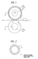
- Fig. 1 is a schematic constitutional view of a fixing device using a fixing rotor according to an embodiment of the present invention.
- Reference numerals 1, 2 represent fixing rotors vertically disposed substantially in parallel to each other, each contacting under a predetermined pressure.
- the reference numeral 1 represents a fixing roller provided on the upper side and the reference numeral 2 represents a pressure roller provided on the lower side.
- Reference numeral 3 represents a heating source such as a halogen heater accommodated within the fixing roller 1, which is controlled for energization by a temperature control circuit containing a fixing roller temperature sensing element (not shown), so that the surface temperature of the fixing roller 1 may be maintained at a predetermined temperature.
- a heating source such as a halogen heater accommodated within the fixing roller 1, which is controlled for energization by a temperature control circuit containing a fixing roller temperature sensing element (not shown), so that the surface temperature of the fixing roller 1 may be maintained at a predetermined temperature.
- the fixing roller 1 has a primer layer 1 b such as PAI applied on the surface of a core metal lc made of a metal such as aluminum in accordance with an ordinary process, and an offset prevention covered layer la laminated thereon.
- the offset prevention covered layer la is a burned layer composed of fluororesin such as PTFE resin or PFA resin having a hollow double shell conductive substance contained as the filler, as will be described later.
- the pressure roller 2 has a silicone rubber layer 2a covered on the surface of a core metal 2b.
- a pair of rollers 1, 2 as described are driven for rotation at a predetermined speed by driving means (not shown).
- P is a recording medium having an unfixed toner image T formed thereon by image forming means (not shown), the recording medium being introduced into a pinching portion N (fixing nip, nip width: 5 to 6 mm) between the pair of rollers 1, 2, and subjected tofixing of a toner image by heat and pressure while being carried through the pinching portion.
- the fixing roller 1 in this embodiment is formed in such a way that the core metal lc is made from an aluminum pipe having a diameter of 40 mm, its external curved surface being subjected to honing with alumina powder #100 to make the surface rough, the primer layer Ib containing a conductive filler is applied thereon about 10 ⁇ m thick and then dried at 150°C for fifteen minutes, and the offset prevention covered layer la is formed in which a fluororesin compound of PTFE resin and PFA resin having a mixing ratio of 70 to 30 with a hollow double shell conductive substance as described below contained as the filler is applied thereon about 10 ⁇ m thick and burned at 400°C for twenty minutes, and after burning, the fixing roller 1 is polished with a sand paper of #1000 as final finishing.
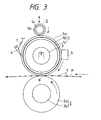
- the hollow double shell conductive substance for use in this embodiment is comprised of an inner shell which is hollow, and an outer shell a covering the surface of the inner shell band composed of a substantially conductive oxide, as shown in the model view of Fig. 2.
- the inner shell b is made of amorphous silica
- the outer shell a is made of tin oxide and antimony trioxide, with the thickness of each shell being 5 to 20 nm.
- This substance is hollow planar or spherical particles having a particle diameter of one (1) to several tens ⁇ m (an average particle diameter of 3 ⁇ m in this embodiment), with the density being as low as 0.3 to 0.4 g/cc and the specific surface being as large as 40 to 60 m 2 /g, and has quite excellent dispersibility with the fluororesin composition.
- the fixing rollers having the different contents (wt%) of hollow double shell conductive substance as the filler in the offset prevention covered layer la of 5, 10, 15, 20 and 25 were produced, and measured and evaluated in the following items.
- the fixing rollers having the different contents (wt%) of 0, 5, 15 and 25 were fabricated using whisker-like single crystal of potassium titanate, instead of hollow double shell conductive substance, as the filler to be mixed into the offset prevention covered layer la in the fixing roller.
- Other conditions for constituting the fixing rollers were the same as those of this embodiment.
- the fixing rollers having different contents (wt%) of 5,15 and 25 were fabricated using a filler of carbon particulates (CB#44 made by Mitsubishi Kasei Corparation). Other conditions for constituting the fixing rollers were the same as those of this embodiment.
- the fixing roller has an excellent offset preventing effect by adding a filler of hollow double shell conductive substance to the offset prevention covered layer la of fluororesin. Also, it has been observed that regarding the durable life there is a sufficient effect of improving the wear resistance with the addition of a slight amount of filler.
- the fixing rollers of comparative example 1 exhibited the effect of offset prevention but no effect of improving the wear resistance, resulting in poor durable life.
- the fixing rollers of comparative example 2 exhibited particularly no effect of improving the offset prevention and the wear resistance.
- the fixing device of this embodiment is allowed to satisfy both the excellent electrostatic offset prevention ability and the wear resistance (durability) simultaneously by using a hollow double shell conductive substance as the filler to be added to the offset prevention covered layer la of the fixing roller.
- This embodiment involves a roller in which the fixing roller of the previous embodiment 1 is subjected again to burning treatment after the polishing which is performed as the final finishing.
- This fixing roller was measured and evaluated with respect to the items 1) to 4), and the results are shown in Table 2.
- the offset proof is improved because minute polished trails attached on the fluororesin surface of the offset prevention covered layer 1a for the fixing roller 1 by surface polishing are burned again and remelted to make the surface smoother.
- the durable life is degraded because fluororesin is susceptible to heat history resulting in lower surface strength by passing through two burning processes as in this embodiment.
- This embodiment involves a non-polished roller in which the fixing roller of the embodiment 1 is not subjected to polishing treatment as the final finishing.
- This fixing roller was measured and evaluated with respect to the items 1) to 4), and the results are shown in Table 2.
- This embodiment involves a roller in which the fixing rollerof the embodiment 1 is subjected to a smoothing treatment (leveling treatment) of the offset prevention covered layer la with PTFE film orthe like before burning of the offset prevention covered layer la, and then to a burning treatment, thus having no polishing process as the final finishing treatment.
- This fixing roller was measured and evaluated with respect to the items 1) to 4), and the results are shown in Table 2.
- This embodiment can satisfy either of the offset proof and the durable life simultaneously because there is no burning process performed again after the smoothing treatment (polishing process) of the fixing roller.
- PTFE resin has a good lubricating ability of solid, but contains a lot of pin holes within the film, and when a filler is mixed therein, cracks may often occur near the filler. To prevent such cracks from occurring, it is often practiced to mix a PFAresin having high fluidity therein, but the conventional fillers became less adherent after burning, and also produced cracks near the filler after cooling.
- the filler used is a hollow double shell conductive substance having a hollow inner shell and an outer shell covering the surface of the inner shell and substantially made of a conductive oxide
- the bulk density is small and the dispersibility in the resin is very excellent because the filler is hollow, thus it has a three dimensional bridged structure in the resin, and the fluororesin layer as the offset prevention covered layer la can be toughened.
- the offset prevention covered layer la forthe fixing roller is made of a mixed compound composed of PTFE resin and PFA resin as resin fraction, with the mixing ratio of PFA resin being greater than that of PTFE resin, using a hollow double shell conductive substance as the filler, an even and smooth offset prevention covered layer extremely superior in the wear resistance can be formed, whereby a fixing device having the excellent durability and non-adhesive properties can be constituted.
- Fig. 3 is a schematic constitutional view of a fixing device according to this embodiment.
- the same numerals are attached to common components to those of Fig. 1, the explanation of which is omitted.
- Reference numeral 4 represents a temperature sensing element such as a thermistor placed in contact with the surface of a fixing roller 1.
- the surface temperature of the fixing roller 1 is sensed by this element 4, and a heating source 3 is controlled for the energization by a control- circuit (not shown) in accordance with this sensed information, so that the surface temperature of the fixing roller 1 may be maintained at a predetermined temperature.
- Reference numeral 5 represents a roller body as the oil supply member as well as cleaning member for the fixing roller 1.
- This roller body is comprised of a core metal 5a and an oil impregnated heat resistant felt 5b, and controlled by an eccentric cam (not shown) or the like to move toward or away from the fixing roller 1.
- the oil supply amount is 0.3 to 0.5 mg upon each one time of contact.
- Reference numeral 6 represents a recording medium separation claw which is biased and contacted by a spring 7 against the fixing roller 1, which serves to separate the recording medium tending to attach to and wrap around the surface of the fixing roller 1 therefrom.
- the fixing roller 1 in this embodiment comprises a core metal 1c made of iron or aluminum subjected to blasting treatment with a powder of #100 alumina, a primer layer 1 applied thereon about 5 to 10 f..lm thick and dried at 150°C for fifteen minutes, and an offset prevention covered layer 1a having fluororesin compound with the following constitution applied 10 to 20 ⁇ m thick, and is burned at 390 to 400°C for twenty minutes.
- Fluororesin mixture composed of PTFE resin and PFA resin at a mixing ratio of 45 to 55 or 30 to 70 b.
- Hollow double shell conductive particles comprising a hollow inner shell composed of amorphous silica and an outer shell substantially composed of tin oxide (IV) and antimony trioxide, with the average particle diameter of about 3 ⁇ m, the bulk density of 0.3 to 0.4 g/cc, and the thickness of each of inner shell and outer shell being from several tens nm to 200 nm.
- filler rollers having the contents of filler of 5 wt% or 15 wt% in b were made, and measured and evaluated with respect to the following items.
- Durable life Evaluated by the cut or flaw on the surface after continuous passing of sheets through the actual machine
- the fixing rollers using as the filler a whisker-like single crystal of potassium titanate, with the average particle diameter being equal to length (5 ⁇ m) x breadth (0.3 pm), and carbon black CB#44 (made by Mitsubishi Kasei Corporation) were measured and evaluated with respect to the items 1) to 4), and the results are shown in Table 3.
- This embodiment involves a fixing device in which the oil supply and cleaning member 5 of the roller type in the fixing device (Fig. 3) of the embodiment 5 is replaced with an oil supply and cleaning unit 10 of the web type as shown in Fig. 4.
- Reference numeral 11 represents an oil impregnated heat resistant web
- reference numeral 12 represents a web supply roller
- reference numeral 13 represents a web winding roller
- reference numeral 14 represents a web pressure roller such as a heat resisting silicone sponge roller.
- the web pressure roller 14 presses the oil impregnated web 11 against the surface of the fixing roller 1, several mm in width, to supply a releasing agent such as the oil onto the surface of the fixing roller 1 and remove contamination on the roller surface after fixing with the surface of the fixing roller 1.
- the web 11 is fed by a predetermined length in a counter direction of the fixing roller 1 in accordance with the size of the recording medium.
- the feeding of the web was performed by the length of, for example, 0.05 mm per one recording sheet of A4 size.
- the fixing device of the embodiment 5 by using a hollow double shell conductive substance as the filler for the offset prevention covered layer of the fixing roller 1, and a mixed compound of PTFE resin and PFA resin having the mixing ratio of PFA resin being greater than that of PTFE resin, the sufficient offset prevention effect could be obtained with the web feeding amount being one-third to one-fourth that as noted above.
- This embodiment uses a heat resistant felt pad 15 having a releasing agent such as oil impregnated therein as the oil supply and cleaning means for the fixing roller 1 as shown in Fig. 5.
- the face of member contacted by the surface of the fixing roller is not a new face, unlike the roller type 5 in the embodiment 5 or the web type 10 in the embodiment 6, the paper powder of paper edge portion or a part of offset toner may be left in the pad portion, often damaging the fixing roller acceleratively.
- the pad surface was contaminated with ten thousands to twenty thousands copies of A4 size, resulting in less smooth surface of the fixing roller, whereas in this embodiment the durability could be improved over three times.
- Fig. 6 is a view in which the fixing roller 1 of the fixing device is contacted by a cleaning blade 16.
- the filler to be mixed into the offset prevention covered layer la of the fixing roller 1 was a hollow double shell conductive substance comprising a hollow inner shell composed of amorphous silica or silica containing substance and an outer shell substantially composed of tin oxide (IV) and antimony trioxide.
- tin oxide (IV) and antimony trioxide In the case of a positive toner, fluororesin on the surface of the fixing roller is electrified negatively, resulting in quite unfavorable electrostatic offset. But, in the case of a negative toner, the electrostatic offset is favorable, so that the conductive substance of the outer shell is unnecessary.
- the hollow substance composed of amorphous silica or silica containing substance can sufficiently meet the main purpose of the present invention, and it is needless to say that various actions and effects as described can be also provided.
- the hollow double shell conductive substance as the filler to be mixed into the offset prevention covered layer la can take a three dimensional bridged structure in the resin, because the filler is hollow and has a small bulk density and an extremely excellent dispersibility in the resin, whereby the offset prevention covered layer for the fixing roller can be toughened.
- the filler is composed of planar or spherical particles having a hollow interior and an adequately porous surface. Accordingly, it has been found that if the releasing agent such as oil is once applied onto the surface of fluororesin layer having such particles thereon, the oil component may be held inside of particles, so that the offset prevention covered layer can exhibit a stable non-adhesive properties over the long term.
- the offset prevention covered layer la for the fixing roller 1 was formed by fluororesin compound having the following composition.
- Fluororesin mixture composed of PTFE resin and PFA resin at a mixing ratio of 70 to 30
- the fixing rollers using as the filler a whisker-like single crystal of potassium titanate having the average particle diameter being equal to length (5 f..lm) x breadth (0.3 f..lm) and carbon black CB#44 (made by Mitsubishi Kasei Corporation) were measured and evaluated in the same way, and the results are shown in Table 5.
- the conventional filler (comparative example 2) contained in fluororesin may cause abrasion as stripe-like flaws on the surface of the offset prevention covered layer la due to the filler contained in the paper, because of greatly not tough material itself, and simultaneously may produce an offset because of the poor smoothness.
- the fixing roller of this embodiment can sustain sufficient effect of oil releasing ability, because the offset proof after the durable use is not degraded by significantly reducing the oil supply amount.
- the wear resistance is superior even from the microscopic aspect because the dispersibility of the filler itself is excellent, and the filler has high oil holding ability due to the shape effect of particles despite the poor oil absorbing ability of the filler material itself, contributing greatly to the improvement of wear resistance.
- the oil application fixing roller used in this embodiment can retain the releasing ability of the fixing roller, even though the number of oil supplies is reduced, which means that the oil utilization efficiency is excellent. That is, even if excess oil is supplied, it is simply brought away by the recording medium P. Therefore, the good utilization efficiency results.
- the fixing system allows the life of the oil application roller to be lengthened, and the service interval to be elongated, and it can be said that the cost performance is also excellent.
- This embodiment involves a fixing roller in which oil supply and cleaning means for the fixing roller in the embodiment 9 is replaced with that of the web type having the web feeding amount reduced as shown in Fig. 4 of the embodiment 6.
- the durable life of the fixing roller is extended two to three times. And the life of the web is also extended two to three times.
- the fixing roller having a hollow double shell conductive substance as the filler mixed into the offset prevention covered layer with the oil supply device, a highly durable fixing device with high cost performance can be developed.
- the web life can be lengthened within the permissible range of offset proof/wear resistance.
- This embodiment involves a fixing roller in which oil supply and cleaning means for the fixing roller in the embodiment 9 is replaced with that of the pad type as shown in Fig. 5 with the embodiment 7.
- the filler for use in the fixing rotter was a hollow double shell conductive substance comprising a hollow inner shell made of amorphous silica or silica containing substance and an outer shell substantially made of tin oxide (IV) and antimony trioxide.
- fluororesin of the fixing roller is electrified negatively, resulting in quite unfavorable electrostatic offset, while in the case of a negative toner, the electrostatic offset is favorable, so that the conductive substance of the outer shell is not necessarily provided.
- the hollow substance composed of amorphous silica or silica containing substance can sufficiently meet the main purpose of the present invention, and it is needless to say that various actions and effects as described can be also obtained.
- the embodiments 9 to 12 can be achieved to the same effects as in the respects of a to d in the embodiments 5 to 8, and can accomplish the stabilization, the longer life and the lower costs of the fixing system.
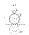
- Fig. 7 is a schematic constitutional view of a fixing device according to an embodiment 13.
- the device of this embodiment has a DC power supply 20 for applying a DC bias having the same polarity (positive (+) in this embodiment) as the toner which allows the image on a core metal lc of a fixing roller 1 to be formed onto the recording medium P.
- the fixing roller 1 and the pressure roller 2 and the constitution for the device are the same as in the embodiment 1 (Fig. 1). That is, the fixing roller 1 has an offset prevention covered layer la which is an applied and burned layer composed of a mixed resin of PTFE resin and PFA resin having a mixing ratio of 70 to 30 to which the filler of hollow double shell conductive substance is added.
- Table 6 lists the evaluation results in which the content (wt%) of the filler and the applied voltage to the core metal lc for the fixing roller are differently changed.
- the measurements for the surface resistance and the abrasion loss for the fixing roller 1 and the evaluation with the actual machine are the same as described in the embodiment 5.
- the fixing rollers using as the filler a whisker-like single crystal of potassium titanate having the average particle diameter being equal to length (5 ⁇ m) x breadth (0.3 ⁇ m) and carbon black CB#44 (made by Mitsubishi Kasei Corporation) were measured and evaluated in the same way, and the results are shown in Table 7.
- the fixing device can satisfy both the excellent offset proof and the durable life simultaneously by using fluororesin containing hollow double shell conductive particles on the surface layer 1a of the fixing roller 1, and applying a DC bias having the same polarity as the toner.
- the hollow double shell conductive substance is hollow, and hence has a small bulk density and large surface area, resulting in very excellent dispersibility in the resin, and easy formation of a three dimensional bridge structure. Accordingly, the surface layer la of he fixing roller can be toughened and the resistance is remarkably reduced owing to the above-described effect of the filler.
- the excellent offset prevention effect can be exhibited by applying a slight DC bias to the core metal 1c, because this fixing roller 1 has its surface resistance remarkably decreased.
- This embodiment involves a fixing roller in which the mixing ratio of PTFE resin and PFAresin of the offset prevention covered layer la for the fixing roller 1 is differently changed as listed in Table 8, and the evaluation results of the fixing roller are shown in Table 8.
- This embodiment is accomplished in that the application of DC bias to the fixing roller 1 is performed in such a manner that while the fixing roller 1 is rotatably driven with a conductive sponge roller 21 contacting the surface of the fixing roller 1, a DC bias from a power supply 20 is applied to this conductive sponge roller 21, so that the DC bias having the same polarity as the toner is applied directly to a surface layer la of a fixing roller 1.
- This embodiment has also exhibited the same excellent effects as in the embodiments 13 and 14.
- the life of the fixing device could be remarkably improved as a whole.
- hollow double shell conductive particles as the filler to be added to the offset prevention covered layer of the fixing roller can greatly improve the offset prevention and the durability for the fixing roller.
- Double shell conductive particles as the filler for use in this embodiment are of hollow planar or spherical shape, with the volume average particle diameter being about 3 wm.
- the average particle diameter of the toner typically used in the electrophotographic device at present is about 8 to 10 ⁇ m, accordingly, the filler for use in this embodiment is one-half to one third that average particle diameter of the toner.
- the fixing roller coated with fluororesin having mixed such filler therein can hold two to three times the durable life (durable offset proof, wear resistance and anti-flaw ability) of the fixing roller coated with fluororesin using the conventional fillers which is equivalent to about ten thousands sheets of A4 size.
- the fitter for use with the present invention can provide a fixing roller excellent in the anti-offset ability and the wear resistance from the following reasons:
- the fixing device of this embodiment applies a DC bias to the core metal 1c of the fixing roller 1, like the device of Fig. 7 in the embodiment 13.
- the toner for use in this embodiment is a positive charged toner, and therefore prevents the electrostatic offset by applying a positive (+) DC bias to the core metal lc of the fixing roller 1.
- the fixing roller 1 and the pressure roller 2 and the device constitution are the same as in the embodiment 1. That is, the fixing roller 1 has the offset prevention covered layer 1 a which is an applied and burned layer composed of a resin compound of PTFE resin and PFA resin having a mixing ratio of 70 to 30, to which hollow double shell conductive particles are added as the filler.
- the offset prevention covered layer 1 a which is an applied and burned layer composed of a resin compound of PTFE resin and PFA resin having a mixing ratio of 70 to 30, to which hollow double shell conductive particles are added as the filler.
- Table 9 lists the durable evaluation results with actual machine when the average particle diameter, average pore diameter, and the content of hollow double shell conductive particles as the filler and the toner particle diameter are varied.
- the fixing rollers using as the filler a whisker-like single crystal of potassium titanate having the average particle diameter being equal to length (5 ⁇ m) x breadth (0.3 pm), silicon carbide power and Ni powder were measured and evaluated in the same way, and the results are shown in Table 9.
- silicon carbide powder and Ni powder will produce stripe-like cutting in the durable use though the abrasion loss is relatively small, producing stripe-like blurs in the image with the actual machine. Also, as a result of stripe-like blurs cutting, the toner is more likely to remain, easily causing the offset.
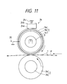
- This embodiment is accomplished in that a DC bias is applied to the fixing roller of the fixing device in the embodiment 16, and a roller 22 for applying a releasing agent such as diamethyl-silicon oil is provided.
- the roller 22 has a heat resistant felt 22c (trade name Nomex, made by Du Pont), for example, wound around double cylindrical core metals 22a, 22b.
- Acore metal 22b has a minute pore opened and has a releasing agent between the core metals 22a and 22b. The releasing agent will exude into the heat resistant felt 22c little by little to be applied on the surface of fixing roller 1.
- the actions and effects of the embodiment 16 are further enhanced, and the anti-offset ability and the durable life can be excellently enhanced as evidenced by a longer life as many as thirty thousands sheets.
- the fixing roller could be maintained clean because there was no toner left in the hollow portion of the fitter and less filler getting off, further owing to the additional effect of the releasing agent.
- This embodiment is accomplished in that the releasing agent application means in the fixing device (Fig. 9) of the embodiment 17 is replaced with web type means 23.
- Reference numeral 23a consists of a heat resistant elastic roller which is brought into contact with the fixing roller 1 with a predetermined nip.
- 23b is a winding roller and 23c is a heat resistant roller around which an oil impregnated web 23d is wound.
- the web 23d is wound by a predetermined length every time one recording medium is passed therethrough, and the toner or paper powder remaining on the fixing roller 1 can be cleaned off by the web cleaning.
- the fixing roller 1 is always held clean.
- the fixing roller is less contaminated even if there is protruding filler mixed into fluororesin of the offset prevention covered layer 1 a, because the particle diameter of the toner is smaller than the diameter of the hollow portion for the filler, and since the fixing roller 1 is always held clean by the cleaning web 23d, the fixing roller 1 is prevented from being contaminated to the utmost, whereby it has been confirmed that the life of the fixing roller is extended to two to three times the life of the fixing roller as indicated in the embodiment 16.
- This embodiment is accomplished in that the releasing agent application means in the fixing device (Fig. 9) of the embodiment 17 is replaced with the pad type means 24.
- Reference numeral 24a is a heat resistant felt pad having the oil impregnated therein, and 24b is a holding member, wherein the pad 24a is placed into contact with the fixing roller 1 by a biasing force of a spring 24c.
- the fluororesin for the offset prevention covered layer la of the fixing roller 1 is composed of PTFE resin and PFA resin having a mixture ratio of 70 to 30, this ratio is changed in this embodiment.
- the greater mixture ratio of PFA resin the larger wear resistant effect provided against the frictional member such as a paper.
- the fixing roller 1 may be weakened to nick flaws which may be caused by the separation claw, whereby a compound of PTFE resin and PFA resin is excellent.
- a test was performed using a fixing roller in which a filler of hollow double shell conductive particles were mixed into fluororesin composed of PTFE resin and PFA resin having a ratio of 30 to 70, so that excellent results could be obtained against both the nick flaws by the separation claw and the flaws rubbed by the paper.
- the volume resistance for the surface layer (primer layer plus offset prevention covered layer) of the fixing roller will decrease with the durable offset proof enhanced if an appropriate conductive filler is contained in the primer layer, but on the contrary, the adhesion may decrease.
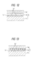
- the volume resistance of the surface layer can be decreased by conducting the blasting or defining the thickness of the primer layer 1 b so that the apex 1c" of the surface 1c' of the core metal 1c for the fixing roller 1 subjected to blasting treatment may be outside the primer layer 1 b, or inside of the offset prevention covered layer la, without containing any conductive filler in the primer layer.
- one of the problems associated with the fixing roller 1 in the form of Fig. 13 is a corrosion of the core metal 1c. That is, typically, the recording medium such as a paperwill produce much watervaporwhen heated at the nip portion between the fixing roller and the pressure roller as it has absorbed moisture to some extent.
- the fixing roller has the core metal 1c blasted with the apex 1c" reaching the offset prevention covered layer 1 a, and the offset prevention covered layer la typically made of fluororesin such as PTFE resin, therefore, is not complete continuous film, so that the apex 1c" of the core metal 1c blasted is always exposed to water vapor penetrating the offset prevention covered layer 1a.
- the apex portion 1c" as blasted is gradually corroded, and finally warty alien matter is produced on the offset prevention covered layer 1a, and makes the fixing roller unusable.
- This embodiment has solved the problems with the corrosion of the apex 1c" of the blast surface 1c' of the core metal 1c for the fixing roller 1 and irregularities on the surface of the fixing roller, as previously described in Fig. 13.
- the surface roughness of the core metal 1c for the fixing roller 1 is made such that the maximum value Tmax is less than the thickness t (average film thickness) of the primer layer 1 b, or preferably 0 ⁇ t-Rmax ⁇ 10 ⁇ m.
- the fixing roller 1 was produced in the following manner.
- the primer PAI type insulating primer
- the primer having a conductive filler blended is applied thereon about 10 f..lm thick to form a primer layer 1 so that the blast surface of the core metal 1c is entirely hidden within the primer layer, and dried at 150°C for fifteen minutes.
- fluororesin having a hollow double shell conductive substance as the filler blended is applied about 10 ⁇ m thick on the surface, and burned at 400°C for twenty minutes to form an offset prevention covered layer la.
- the abrasive finishing was made with #1000 sand paper.
- This embodiment is accomplished in that instead of adding the filler to fluororesin of the offset prevention covered layer la for the fixing roller 1 in the embodiment 22, the surface layer of mica having an average particle diameter of 10 f..lm is subjected to conductive treatment with tin oxide and antimony trioxide.
- This embodiment is accomplished in that the core metal 1c in the fixing roller 11 of the embodiment 22 is made of iron.
- the fixing roller having the core metal 1 c made of iron is weak against corrosion, but it exhibited excellent characteristics in this embodiment.
- This embodiment has omitted the polishing treatment as the final finishing for the fixing roller 1 in the embodiment 22.
- This fixing roller exhibited the same excellent effects as in the embodiment 22.
- the life of the fixing device could be remarkably improved.
- the fixing devices in the embodiments 26 to 28 as will be described below have the following features.
- the wear resistant characteristic was excellent for a certain period from the initial time, but thereafter, owing to the filler off the surface layer, in some instances, the surface was abraded to cause a marked flaw.
- the constitution of the fixing roller 1 and the pressure roller 2 and the device constitution in this embodiment are the same as those in the embodiment 1.
- the filler to be added to the offset prevention covered layer la is a hollow double shell conductive substance having an average particle diameter of 3 ⁇ m and consisting of an inner shell made of amorphous silica having a Mohs' hardness of 7, and an outer shell made of tin oxide and antimony trioxide.
- Table 11 lists the abrasion loss and evaluation results with actual machine for the fixing rollers having different mixing ratio (wt%) of the filler. The measurement and evaluation are the same as described in the embodiment 5.
- the offset performance and wear resistance could be satisfied at the same time, and were quite excellent as a whole.
- the surface layer may be flawed, as may occur with the powder or particle filler, while if it is 3 or less, the effectiveness of improving the wear resistance is low.
Landscapes
- Physics & Mathematics (AREA)
- General Physics & Mathematics (AREA)
- Fixing For Electrophotography (AREA)
- Braking Arrangements (AREA)
- Processes Of Treating Macromolecular Substances (AREA)
- Rolls And Other Rotary Bodies (AREA)
Applications Claiming Priority (3)
| Application Number | Priority Date | Filing Date | Title |
|---|---|---|---|
| JP30761592A JP3679422B2 (ja) | 1992-10-21 | 1992-10-21 | 定着装置 |
| JP307615/92 | 1992-10-21 | ||
| JP30761592 | 1992-10-21 |
Publications (3)
| Publication Number | Publication Date |
|---|---|
| EP0594546A2 true EP0594546A2 (de) | 1994-04-27 |
| EP0594546A3 EP0594546A3 (en) | 1994-06-08 |
| EP0594546B1 EP0594546B1 (de) | 1999-12-15 |
Family
ID=17971166
Family Applications (1)
| Application Number | Title | Priority Date | Filing Date |
|---|---|---|---|
| EP93830419A Expired - Lifetime EP0594546B1 (de) | 1992-10-21 | 1993-10-19 | Fixierrolle mit einer Schutzschicht aus leitfähigen Teilchen in Form einer hohlen Doppelschale als Füllmaterial gegen Offset |
Country Status (6)
| Country | Link |
|---|---|
| US (1) | US5717988A (de) |
| EP (1) | EP0594546B1 (de) |
| JP (1) | JP3679422B2 (de) |
| CN (1) | CN1054925C (de) |
| DE (1) | DE69327298T2 (de) |
| ES (1) | ES2143497T3 (de) |
Families Citing this family (30)
| Publication number | Priority date | Publication date | Assignee | Title |
|---|---|---|---|---|
| JPH09250539A (ja) * | 1996-03-19 | 1997-09-22 | Shin Etsu Polymer Co Ltd | 半導電性ロールとその製造方法 |
| JPH10180874A (ja) * | 1996-12-27 | 1998-07-07 | Canon Inc | フッ素樹脂チューブの被覆方法および該被覆方法により製造された定着部材 |
| JPH10213988A (ja) * | 1997-01-31 | 1998-08-11 | Sharp Corp | 定着部材、定着ローラ及び定着装置 |
| JP3880208B2 (ja) * | 1997-07-28 | 2007-02-14 | キヤノン株式会社 | 加熱加圧定着装置およびシリコーンゴムローラ |
| US6377777B1 (en) | 1999-02-19 | 2002-04-23 | Canon Kabushiki Kaisha | Fluorine-containing resin-coated pressure roller and heat-fixing device |
| US6321062B1 (en) | 1999-03-09 | 2001-11-20 | Canon Kabushiki Kaisha | Fixing-unit roller making use of composite material, process for its production, and fixing assembly employing the roller |
| JP2001005342A (ja) | 1999-06-24 | 2001-01-12 | Canon Inc | 画像形成装置 |
| DE10042303A1 (de) * | 1999-08-31 | 2001-03-01 | Nexpress Solutions Llc | Elektrophotographisches Element mit gesteuerter Rauheit |
| US6459878B1 (en) | 1999-09-30 | 2002-10-01 | Canon Kabushiki Kaisha | Heating assembly, image-forming apparatus, and process for producing silicone rubber sponge and roller |
| JP2001183937A (ja) | 1999-10-14 | 2001-07-06 | Canon Inc | オイル塗布ローラ、オイル塗布装置および定着装置 |
| JP2001183935A (ja) * | 1999-12-27 | 2001-07-06 | Nitto Kogyo Co Ltd | 定着用ローラ |
| JP2001188433A (ja) * | 2000-01-05 | 2001-07-10 | Nissei Electric Co Ltd | 定着用加熱ローラ |
| US6490431B2 (en) | 2000-04-05 | 2002-12-03 | Minolta Co., Ltd. | Fixing rotatable member for heat fixing device and fixing device using the same |
| US20050032617A1 (en) * | 2000-04-13 | 2005-02-10 | Hokushin Corporation | Roller member |
| JP4510310B2 (ja) * | 2000-05-15 | 2010-07-21 | キヤノン株式会社 | 定着部材、定着装置、及び画像形成装置 |
| JP2002296840A (ja) * | 2001-03-30 | 2002-10-09 | Brother Ind Ltd | 画像形成装置 |
| US6503674B2 (en) * | 2001-04-24 | 2003-01-07 | Cf Technologies | Component for a printer, fax machine, copier or the like |
| JP2003084609A (ja) * | 2001-06-04 | 2003-03-19 | Ricoh Co Ltd | 定着装置および画像形成装置 |
| JP2003241549A (ja) * | 2001-12-10 | 2003-08-29 | Canon Inc | 像加熱装置 |
| JP4251031B2 (ja) * | 2002-08-06 | 2009-04-08 | 富士ゼロックス株式会社 | 電子写真用定着部品、電子写真用定着エンドレスベルト、及び加熱ロール・ベルト型定着装置 |
| WO2004092599A1 (de) * | 2003-04-11 | 2004-10-28 | Dirk Richter | Walzenbeschichtungsverfahren und beschichtete walze |
| JP4592274B2 (ja) * | 2003-10-17 | 2010-12-01 | 日揮触媒化成株式会社 | 酸化アンチモン被覆シリカ系微粒子、該微粒子の製造方法および該微粒子を含む被膜付基材 |
| JP2005166299A (ja) * | 2003-11-28 | 2005-06-23 | Canon Inc | 加熱装置および画像形成装置 |
| US20070007708A1 (en) * | 2005-06-23 | 2007-01-11 | Kabushiki Kaisha Toshiba | Paper taking out device |
| KR20080006771A (ko) * | 2006-07-13 | 2008-01-17 | 삼성전자주식회사 | 정착롤러 및 이를 채용한 정착유닛 및 화상형성장치 |
| JP5197163B2 (ja) * | 2008-05-28 | 2013-05-15 | キヤノン株式会社 | シート搬送装置及び画像形成装置 |
| JP5532977B2 (ja) | 2009-11-30 | 2014-06-25 | 株式会社リコー | 定着装置及び画像形成装置 |
| JP6171574B2 (ja) * | 2013-05-29 | 2017-08-02 | 富士ゼロックス株式会社 | 定着用加圧ベルト、定着装置、及び画像形成装置 |
| CN104460270B (zh) * | 2014-12-09 | 2021-05-18 | 珠海展望打印耗材有限公司 | 显影辊及处理盒 |
| JP7066972B2 (ja) * | 2017-02-01 | 2022-05-16 | コニカミノルタ株式会社 | 定着部材、画像形成装置、定着方法および画像形成方法 |
Family Cites Families (21)
| Publication number | Priority date | Publication date | Assignee | Title |
|---|---|---|---|---|
| JPS52110638A (en) * | 1976-03-15 | 1977-09-16 | Fuji Xerox Co Ltd | Heat fixing roll for electrophotographic copying machine |
| US4257699A (en) * | 1979-04-04 | 1981-03-24 | Xerox Corporation | Metal filled, multi-layered elastomer fuser member |
| EP0052684B1 (de) * | 1980-11-26 | 1985-09-04 | International Business Machines Corporation | Testverfahren für eine Anzeigseinrichtung |
| JPS582864A (ja) * | 1981-06-29 | 1983-01-08 | Sumitomo Electric Ind Ltd | 加熱定着ロ−ラ |
| JPH0235986B2 (ja) * | 1983-09-01 | 1990-08-14 | Canon Kk | Teichakusochi |
| JPS634287A (ja) * | 1986-06-24 | 1988-01-09 | Canon Inc | 定着ロ−ラ及びその製造方法 |
| JPS635287A (ja) * | 1986-06-25 | 1988-01-11 | Tokyo Keiki Co Ltd | 畜産用識別装置 |
| JPS6417080A (en) * | 1987-07-10 | 1989-01-20 | Ricoh Kk | Fixing roller |
| JPS6459278A (en) * | 1987-08-29 | 1989-03-06 | Nitto Kogyo Kk | Fixing roller of electrophotographic apparatus |
| JPH0285A (ja) * | 1989-01-25 | 1990-01-05 | Daikin Ind Ltd | 加熱定着ローラー |
| JP2673721B2 (ja) * | 1989-05-24 | 1997-11-05 | キヤノン株式会社 | 定着装置 |
| US5049444A (en) * | 1989-12-15 | 1991-09-17 | Xerox Corporation | Silane adhesive system for fusing member |
| US5219612A (en) * | 1989-12-15 | 1993-06-15 | Xerox Corporation | Silane adhesive system for fuser member |
| JP2734146B2 (ja) * | 1989-12-20 | 1998-03-30 | キヤノン株式会社 | 定着装置 |
| US5035950A (en) * | 1990-02-09 | 1991-07-30 | Ames Rubber Corporation | Fluoroelastomer coated fuser roll |
| JP2773387B2 (ja) * | 1990-05-17 | 1998-07-09 | キヤノン株式会社 | 定着装置 |
| JP3072785B2 (ja) * | 1990-06-08 | 2000-08-07 | キヤノン株式会社 | 定着装置 |
| US5376307A (en) * | 1990-08-09 | 1994-12-27 | E. I. Du Pont De Nemours And Company | Fluorocarbon paint composition |
| US5166031A (en) * | 1990-12-21 | 1992-11-24 | Xerox Corporation | Material package for fabrication of fusing components |
| JPH04215683A (ja) * | 1990-12-14 | 1992-08-06 | Minolta Camera Co Ltd | 熱ローラ定着装置 |
| JPH04215684A (ja) * | 1990-12-14 | 1992-08-06 | Minolta Camera Co Ltd | 定着ローラ |
-
1992
- 1992-10-21 JP JP30761592A patent/JP3679422B2/ja not_active Expired - Lifetime
-
1993
- 1993-10-19 EP EP93830419A patent/EP0594546B1/de not_active Expired - Lifetime
- 1993-10-19 ES ES93830419T patent/ES2143497T3/es not_active Expired - Lifetime
- 1993-10-19 DE DE69327298T patent/DE69327298T2/de not_active Expired - Fee Related
- 1993-10-21 CN CN93119175A patent/CN1054925C/zh not_active Expired - Fee Related
-
1996
- 1996-06-06 US US08/659,624 patent/US5717988A/en not_active Expired - Lifetime
Also Published As
| Publication number | Publication date |
|---|---|
| JPH06130849A (ja) | 1994-05-13 |
| HK1014771A1 (en) | 1999-09-30 |
| ES2143497T3 (es) | 2000-05-16 |
| DE69327298T2 (de) | 2000-05-11 |
| CN1054925C (zh) | 2000-07-26 |
| JP3679422B2 (ja) | 2005-08-03 |
| US5717988A (en) | 1998-02-10 |
| CN1086613A (zh) | 1994-05-11 |
| DE69327298D1 (de) | 2000-01-20 |
| EP0594546A3 (en) | 1994-06-08 |
| EP0594546B1 (de) | 1999-12-15 |
Similar Documents
| Publication | Publication Date | Title |
|---|---|---|
| US5717988A (en) | Fixing rotor having an offset prevention layer containing a hollow double shell conductive substance | |
| EP0196231B1 (de) | Entwicklungsgerät | |
| JP7573980B2 (ja) | 画像形成装置 | |
| JP2001005359A (ja) | 画像形成装置のクリーニング装置 | |
| HK1014771B (en) | A fixing rotor having an offset prevention layer which contains hollow double shell conductive particles as a filter | |
| JP4002698B2 (ja) | 現像ローラ | |
| JP2783938B2 (ja) | 弾性ロール | |
| JPH02266383A (ja) | 定着装置 | |
| JP3100801B2 (ja) | 定着ローラ及び定着装置 | |
| JPH10161495A (ja) | 像担持体クリーニング装置及び像担持体クリーニング方法 | |
| EP0997785B1 (de) | Elektrophotographisches Bildherstellungsapparat | |
| JP4807990B2 (ja) | 画像形成装置 | |
| JP2003323070A (ja) | 定着ローラ、その製造方法および加熱定着装置 | |
| JP2002040800A (ja) | トナー担持体及びそれを用いた画像形成装置 | |
| JP2005148322A (ja) | 定着部材、定着装置およびこれらを備えた画像形成装置 | |
| JP5074647B2 (ja) | トナー担持体及び画像形成装置 | |
| JPS58214180A (ja) | 定着用加熱ロ−ル | |
| JP5203544B1 (ja) | 液体現像電子写真装置用ローラー | |
| WO2022163128A1 (ja) | 帯電ロール | |
| JP2004004410A (ja) | 定着ローラと定着装置及び画像形成装置 | |
| JPH08160735A (ja) | 画像形成装置 | |
| JP2002031977A (ja) | 加熱定着ロール | |
| JP2006259246A (ja) | 現像部材及びそれを用いた画像形成装置 | |
| JPH05119504A (ja) | 画像形成装置 | |
| JPS5814174A (ja) | 熱ロ−ラ定着装置 |
Legal Events
| Date | Code | Title | Description |
|---|---|---|---|
| PUAI | Public reference made under article 153(3) epc to a published international application that has entered the european phase |
Free format text: ORIGINAL CODE: 0009012 |
|
| PUAL | Search report despatched |
Free format text: ORIGINAL CODE: 0009013 |
|
| AK | Designated contracting states |
Kind code of ref document: A2 Designated state(s): DE ES FR GB IT NL |
|
| AK | Designated contracting states |
Kind code of ref document: A3 Designated state(s): DE ES FR GB IT NL |
|
| 17P | Request for examination filed |
Effective date: 19941206 |
|
| 17Q | First examination report despatched |
Effective date: 19960329 |
|
| GRAG | Despatch of communication of intention to grant |
Free format text: ORIGINAL CODE: EPIDOS AGRA |
|
| GRAG | Despatch of communication of intention to grant |
Free format text: ORIGINAL CODE: EPIDOS AGRA |
|
| GRAG | Despatch of communication of intention to grant |
Free format text: ORIGINAL CODE: EPIDOS AGRA |
|
| GRAH | Despatch of communication of intention to grant a patent |
Free format text: ORIGINAL CODE: EPIDOS IGRA |
|
| GRAH | Despatch of communication of intention to grant a patent |
Free format text: ORIGINAL CODE: EPIDOS IGRA |
|
| GRAA | (expected) grant |
Free format text: ORIGINAL CODE: 0009210 |
|
| AK | Designated contracting states |
Kind code of ref document: B1 Designated state(s): DE ES FR GB IT NL |
|
| REF | Corresponds to: |
Ref document number: 69327298 Country of ref document: DE Date of ref document: 20000120 |
|
| ET | Fr: translation filed | ||
| ITF | It: translation for a ep patent filed | ||
| REG | Reference to a national code |
Ref country code: ES Ref legal event code: FG2A Ref document number: 2143497 Country of ref document: ES Kind code of ref document: T3 |
|
| PLBE | No opposition filed within time limit |
Free format text: ORIGINAL CODE: 0009261 |
|
| STAA | Information on the status of an ep patent application or granted ep patent |
Free format text: STATUS: NO OPPOSITION FILED WITHIN TIME LIMIT |
|
| 26N | No opposition filed | ||
| REG | Reference to a national code |
Ref country code: GB Ref legal event code: IF02 |
|
| PGFP | Annual fee paid to national office [announced via postgrant information from national office to epo] |
Ref country code: ES Payment date: 20080904 Year of fee payment: 16 |
|
| PGFP | Annual fee paid to national office [announced via postgrant information from national office to epo] |
Ref country code: NL Payment date: 20081017 Year of fee payment: 16 |
|
| PGFP | Annual fee paid to national office [announced via postgrant information from national office to epo] |
Ref country code: DE Payment date: 20081031 Year of fee payment: 16 |
|
| PGFP | Annual fee paid to national office [announced via postgrant information from national office to epo] |
Ref country code: IT Payment date: 20081020 Year of fee payment: 16 |
|
| PGFP | Annual fee paid to national office [announced via postgrant information from national office to epo] |
Ref country code: FR Payment date: 20081024 Year of fee payment: 16 |
|
| PGFP | Annual fee paid to national office [announced via postgrant information from national office to epo] |
Ref country code: GB Payment date: 20081029 Year of fee payment: 16 |
|
| REG | Reference to a national code |
Ref country code: NL Ref legal event code: V1 Effective date: 20100501 |
|
| REG | Reference to a national code |
Ref country code: FR Ref legal event code: ST Effective date: 20100630 |
|
| PG25 | Lapsed in a contracting state [announced via postgrant information from national office to epo] |
Ref country code: NL Free format text: LAPSE BECAUSE OF NON-PAYMENT OF DUE FEES Effective date: 20100501 Ref country code: FR Free format text: LAPSE BECAUSE OF NON-PAYMENT OF DUE FEES Effective date: 20091102 Ref country code: DE Free format text: LAPSE BECAUSE OF NON-PAYMENT OF DUE FEES Effective date: 20100501 |
|
| PG25 | Lapsed in a contracting state [announced via postgrant information from national office to epo] |
Ref country code: GB Free format text: LAPSE BECAUSE OF NON-PAYMENT OF DUE FEES Effective date: 20091019 |
|
| REG | Reference to a national code |
Ref country code: ES Ref legal event code: FD2A Effective date: 20110304 |
|
| PG25 | Lapsed in a contracting state [announced via postgrant information from national office to epo] |
Ref country code: IT Free format text: LAPSE BECAUSE OF NON-PAYMENT OF DUE FEES Effective date: 20091019 |
|
| PG25 | Lapsed in a contracting state [announced via postgrant information from national office to epo] |
Ref country code: ES Free format text: LAPSE BECAUSE OF NON-PAYMENT OF DUE FEES Effective date: 20110303 |
|
| PG25 | Lapsed in a contracting state [announced via postgrant information from national office to epo] |
Ref country code: ES Free format text: LAPSE BECAUSE OF NON-PAYMENT OF DUE FEES Effective date: 20091020 |