EP0595584B1 - System zur Steuerung der Leerlaufdrehzahl und der Kraftstoffdampf-Zurückgewinnung eines Verbrennungsmotors - Google Patents
System zur Steuerung der Leerlaufdrehzahl und der Kraftstoffdampf-Zurückgewinnung eines Verbrennungsmotors Download PDFInfo
- Publication number
- EP0595584B1 EP0595584B1 EP93308489A EP93308489A EP0595584B1 EP 0595584 B1 EP0595584 B1 EP 0595584B1 EP 93308489 A EP93308489 A EP 93308489A EP 93308489 A EP93308489 A EP 93308489A EP 0595584 B1 EP0595584 B1 EP 0595584B1
- Authority
- EP
- European Patent Office
- Prior art keywords
- bypass throttle
- throttle position
- engine
- purge flow
- fuel
- Prior art date
- Legal status (The legal status is an assumption and is not a legal conclusion. Google has not performed a legal analysis and makes no representation as to the accuracy of the status listed.)
- Expired - Lifetime
Links
Images



Classifications
-
- F—MECHANICAL ENGINEERING; LIGHTING; HEATING; WEAPONS; BLASTING
- F02—COMBUSTION ENGINES; HOT-GAS OR COMBUSTION-PRODUCT ENGINE PLANTS
- F02D—CONTROLLING COMBUSTION ENGINES
- F02D31/00—Use of speed-sensing governors to control combustion engines, not otherwise provided for
- F02D31/001—Electric control of rotation speed
- F02D31/002—Electric control of rotation speed controlling air supply
- F02D31/003—Electric control of rotation speed controlling air supply for idle speed control
- F02D31/005—Electric control of rotation speed controlling air supply for idle speed control by controlling a throttle by-pass
-
- F—MECHANICAL ENGINEERING; LIGHTING; HEATING; WEAPONS; BLASTING
- F02—COMBUSTION ENGINES; HOT-GAS OR COMBUSTION-PRODUCT ENGINE PLANTS
- F02D—CONTROLLING COMBUSTION ENGINES
- F02D41/00—Electrical control of supply of combustible mixture or its constituents
- F02D41/0025—Controlling engines characterised by use of non-liquid fuels, pluralities of fuels, or non-fuel substances added to the combustible mixtures
- F02D41/003—Adding fuel vapours, e.g. drawn from engine fuel reservoir
- F02D41/0032—Controlling the purging of the canister as a function of the engine operating conditions
-
- F—MECHANICAL ENGINEERING; LIGHTING; HEATING; WEAPONS; BLASTING
- F02—COMBUSTION ENGINES; HOT-GAS OR COMBUSTION-PRODUCT ENGINE PLANTS
- F02D—CONTROLLING COMBUSTION ENGINES
- F02D41/00—Electrical control of supply of combustible mixture or its constituents
- F02D41/02—Circuit arrangements for generating control signals
- F02D41/04—Introducing corrections for particular operating conditions
- F02D41/08—Introducing corrections for particular operating conditions for idling
Definitions
- the invention relates to idle speed control systems for motor vehicles having fuel vapor recovery systems coupled between the fuel system and engine air/fuel intake.
- Feedback idle speed control systems which control a bypass throttling device, connected in parallel with the primary engine throttle, in response to a difference between desired idling speed and actual idling speed.
- the inventor of the present invention has recognised at least one problem with such idle control systems.
- the fuel vapor recovery system When the fuel vapor recovery system is purged into the engine air/fuel intake during engine idle control, the purged flow may be greater than the airflow required for desired engine idling. Accurate control of engine idling speed may therefore be unachievable under all engine operating conditions. For example, the engine idle may surge even though the bypass throttling device is fully throttled.
- An object of the invention is to control both a bypass throttle and fuel vapor recovery system to achieve accurate engine idle speed control.
- This method and control system according to the invention have the advantage that accurate idle speed control is maintained while purging the fuel vapor recovery system into the engine air/fuel vapor intake.
- Controller 10 is shown in the block diagram of Figure 1 as a conventional microcomputer including: microprocessor unit 12; input ports 14; output ports 16; read only memory 18, for storing control programs; random access memory 20, for temporary data storage which may also be used for counters or timers; keep-alive memory 22, for storing learned values; and a conventional data bus.
- controller 10 controls operation of engine 28 by the following control signals: pulse width signal fpw for controlling liquid fuel delivery; purge duty cycle signal pdc for controlling fuel vapor recovery; and idle speed duty cycle signal ISDC for controlling engine idle speed.
- Controller 10 is shown receiving various signals from conventional engine sensors coupled to engine 28 including: measurement of inducted mass airflow (MAF) from mass airflow sensor 32; indication of primary throttle position (TP) from throttle position sensor 34; manifold absolute pressure (MAP), commonly used as an indication of engine load, from pressure sensor 36; engine coolant temperature (T) from temperature sensor 40; indication of engine speed (rpm) from tachometer 42; and output signal EGO from exhaust gas oxygen sensor 44 which, in this particular example, provides an indication of whether exhaust gases are either rich or lean of stoichiometric combustion.
- MAF inducted mass airflow
- TP primary throttle position
- MAP manifold absolute pressure
- T engine coolant temperature
- rpm engine speed
- exhaust gas oxygen sensor 44 which, in this particular example, provides an indication of whether exhaust gases are either rich or lean of stoichiometric combustion.
- engine 28 is shown having EGO sensor 44 coupled to exhaust manifold 50 upstream of conventional catalytic converter 52.
- Intake manifold 58 of engine 28 is shown coupled to throttle body 54 having primary throttle plate 62 positioned therein.
- Bypass throttling device 66 is shown coupled to throttle body 54 and includes: bypass conduit 68 connected for bypassing primary throttle plate 62; and solenoid valve 72 for throttling conduit 68 in proportion to the duty cycle of idle speed duty cycle signal ISCDC from controller 10.
- Throttle body 54 is also shown having fuel injector 76 coupled thereto for delivering liquid fuel in proportion to the pulse width of signal fpw from controller 10. Fuel is delivered to fuel injector 76 by a conventional fuel system including fuel tank 80, fuel pump 82, and fuel rail 84.
- Fuel vapor recovery system 86 is shown including vapor storage canister 90, connected in parallel to fuel tank 80, for absorbing fuel vapors by activated charcoal contained within the canister. Fuel vapor recovery system 86 is shown connected to intake manifold 58 via electronically actuated purge control valve 88. In this particular example, the cross-sectional area of purge control valve 88 is determined by the duty cycle of actuating signal pdc from controller 10.
- vapor purge air is drawn through canister 90 via inlet vent 92 thereby desorbing hydrocarbons from the activated charcoal.
- the mixture of purged air and recovered fuel vapors is inducted into manifold 58 via purge control valve 88.
- fuel vapors from fuel tank 80 are drawn into intake manifold 58 through valve 88.
- step 102 An open loop calculation of desired liquid fuel is first calculated in step 102.
- the measurement of inducted mass airflow (MAF) is divided by a desired air fuel ratio (AFd) which, in this particular example, is selected for stoichiometric combustion (14.7 lbs. air per 1 lb. fuel).
- AFd desired air fuel ratio
- step 104 the open loop fuel calculation is trimmed by fuel feedback variable FFV to generate desired fuel signal Fd during step 106.
- controller 10 in generating fuel feedback variable FFV to maintain stoichiometric combustion is described later herein with particular reference to Figure 3.
- Purge compensation signal is subtracted from desired fuel signal Fd during step 108 to generate modified desired fuel signal Fdm.
- signal PCOMP represents the mass flow rate of fuel vapors inducted by engine 28 from fuel vapor recovery system 86.
- the modified desired liquid fuel (Fdm) is converted into fuel pulse width signal fpw for actuating fuel injector 76 (step 110). Accordingly, the liquid fuel delivered by fuel injector 76 is both trimmed by feedback from EGO sensor 44 and reduced in proportion to the mass of fuel vapors inducted per unit of time to maintain stoichiometric combustion.
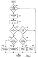
- the air/fuel feedback routine executed by controller 10 to generate fuel feedback variable FFV is now described with reference to the flowchart shown in Figure 3.
- closed loop (i.e., feedback) air/fuel control is desired in step 140
- the desired air/fuel ratio (AFd) is determined in step 144.
- the proportional terms (Pi and Pj) and integral terms (Wi and Wj) of the proportional plus integral feedback control system described below are then determined in step 148. These proportional and integral terms are selected to achieve, on average, air/fuel operation at AFd.
- EGO sensor 44 is sampled in step 150 during each background loop of controller 10.
- proportional term Pj is subtracted from signal FFV in step 158.
- integral term Wj is subtracted from signal FFV in step 162. Accordingly, in this particular example of operation, proportional term Pj represents a predetermined rich correction which is applied when EGO sensor 26 switches from rich to lean.
- Integral term Wj represents an integration step to provide continuously increasing rich fuel delivery while EGO sensor 26 continues to indicate combustion lean of stoichiometry.
- proportional term Pi is added to signal FFV in step 182.
- integral term Wi is added to signal FFV in step 178.
- Proportional terms Pi represents a proportional correction in a direction to decrease fuel delivery when EGO sensor 44 switches from lean to rich
- integral term Wi represents an integration step in a fuel decreasing direction while EGO sensor 44 continues to indicate combustion rich of stoichiometry.
- step 220 When controller 10 is in closed loop or feedback air/fuel control (step 220), and vapor purge is enabled (step 226), signal FFV is compared to its reference or nominal value, which is unity in this particular example. If signal FFV is greater than unity (step 224), indicating a lean fuel correction is being provided, signal PCOMP is incremented by integration value Wp during step 236. The liquid fuel delivered to engine 28 is thereby decreased, or leaned, by Wp each sample time when signal FFV is greater than unity. When signal FFV is less than unity (step 246), integral value Wp is subtracted from signal PCOMP during step 248. Delivery of liquid fuel is thereby increased and signal FFV is again forced towards unity.
- the purge compensation routine executed by controller 10 adaptively learns the mass flow rate of recovered fuel vapors. Delivery of liquid fuel is corrected by this learned value (PCOMP) as shown in Figure 2 to maintain stoichiometric combustion while fuel vapors are recovered or purged.
- PCOMP this learned value
- ISC closed loop idle speed control
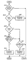
- a desired (or reference) idle speed DIS is calculated as a function of engine operating conditions such as engine speed (rpm) and coolant temperature (see step 306).
- the previous idle speed feedback variable ISFV is also reset to zero (see step 308) at the beginning of each idle speed control period.
- step 310 the appropriate load operating cell is selected to receive idle speed correction.
- Controller 10 then calculates desired throttle position for bypass throttling device 66 (step 312).
- the desired idling speed DIS at the beginning of the idle speed control period is converted into a bypass throttle position, typically by a look-up table, and this initial throttle position is corrected by idle speed learned correction ISLC.
- signal ISLC is based upon the error between the initial throttle position (derived from DIS) and the actual throttle position which feedback control maintained to operate at the desired idle speed DIS.
- step 312 the corrected throttle position (desired or initial position corrected by signal ISLC) is further corrected by the idle speed feedback variable ISFV, the generation of which is described below.
- the idle speed duty cycle ISDC for operating solenoid valve 72 of bypass throttling device 66 is then calculated in step 316. This duty cycle moves the bypass throttle to the value calculated in step 312.
- Controller 10 in this one example of operation, provides a dead band with hysteresis around desired idle speed DIS in steps 320 and 322.
- DIS minus W1 idle speed feedback variable ISFV is increased by predetermined amount Wx in step 326.
- ISFV is decreased by predetermined amount Wy in step 328. Accordingly, ISFV will appropriately increase or decrease the bypass throttle position (see step 312) to maintain, on average, desired idle speed DIS.
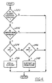
- step 400 idle speed duty cycle ISDC is compared to a dead band in steps 402 and 404. If ISDC is less than the dead band (selected as 20% duty cycle in this example), the purge flow is decreased a predetermined increment in step 408. More specifically, the duty cycle of purge duty cycle signal pdc from controller 10 is decreased a predetermined percentage thereby decreasing purge flow through purge valve 88.
- idle speed duty cycle ISDC is greater than the dead band, increases in purge flow are enabled (steps 404 and 416). More specifically, purge duty cycle pdc is incremented when both idle speed duty cycle ISDC is above the dead band and EGO sensor 44 has changed states since the last background loop of controller 10.
- idle speed duty cycle ISDC determines bypass throttle position.
- 25% idle speed duty cycle is substantially equivalent to 25% of the maximum bypass throttle position.
- purge flow is maximized without impinging on the ability of the feedback idle speed control to maintain accurate control. Further, air/fuel transients are minimized while purging at a maximum rate during idle speed control.
Landscapes
- Engineering & Computer Science (AREA)
- Chemical & Material Sciences (AREA)
- Combustion & Propulsion (AREA)
- Mechanical Engineering (AREA)
- General Engineering & Computer Science (AREA)
- Electrical Control Of Air Or Fuel Supplied To Internal-Combustion Engine (AREA)
- Supplying Secondary Fuel Or The Like To Fuel, Air Or Fuel-Air Mixtures (AREA)
Claims (11)
- Eine Methode zur Steuerung des Leerlaufs eines Motors (28) mit einer Umgehungs-Drosselklappe (66), die parallel zu einer primären Motordrosselklappe (62) angeschlossen ist und einer Entleerungsströmung durch ein Dampf-Rückgewinnungssystem (86) in eine Luft/Kraftstoff-Einströmungs-Rohrleitung (58) des Motors (28), die folgende Stufe beinhaltet:Positionieren der Umgehungs-Drosselklappe (66), um jeglichen Unterschied zwischen einem gewünschten Leerlauf und dem wirklichen Leerlauf des Motors zu verringern; durch die folgende Stufe gekennzeichnet:Verringerung der Entleerungsströmung, wenn die besagte Umgehungs-Drossselklappenstellung geringer als eine vorgewählte Fraktion einer maximalen Umgehungs-Drosselklappenstellung ist.
- Eine Methode nach Anspruch 1, die ausserdem die Stufe enthält, die Entleerungsströmung erhöhen zu können, wenn die besagte Umgehungs-Drosselklappenstellung grösser als eine vorbestimmte Fraktion der besagten maximalen Umgehungs-Drosselklappenstellung ist, wobei die vorbestimmte Fraktion grösser als die besagte vorgewählte Fraktion ist.
- Eine Methode nach den Ansprüchen 1 und 2, in der die Entleerungsströmung erhöht wird, wenn die besagte Umgehungs-Drosselklappenstellung grösser als eine vorbestimmte Fraktion der besagten maximalen Umgehungs-Drosselklappenstellung ist und die von einem Abgas-Sauerstoff-Messfühler (44) abgeleitete Rückführung angibt, dass der gewünschte Luft/Kraftstoffvorgang des Motors beibehalten werden kann, während die Entleerungsströmung erhöht wird.
- Eine Methode nach Anspruch 3, in der die besagte Stufe hinsichtlich der Reduzierung der Entleerungsströmung, die von der besagten Rückführung abhängt, ausserdem eine Stufe hinsichtlich der Bestimmung des Zeitpunkts enthält, an dem der besagte Abgas-Sauerstoff-Messfühler (44) von einem Zustand mit Abgasen aus einer reichen stöchiometrischen Verbrennung auf einen anderen Zustand mit Abgasen aus einer armen stöchiometrischen Verbrennung umschaltet.
- Eine Methode nach Anspruch 3, in der die besagte Stufe der Reduzierung der Entleerungsströmung ebenfalls die Entleerungsströmung verringert, wenn die Rückführung von einem Abgas-Sauerstoff-Messfühler (44) einen Luft/Kraftstoff-Motorbetrieb angibt, der reich an stöchiometrischer Verbrennung für eine vorgewählte Zeit ist.
- Eine Methode nach Anspruch 1 oder 2, die ausserdem die Stufe enthält, die jegliche Steigerung der Entleerungsströmung unterbindet, wenn sich die besagte Umgehungs-Drosselklappenstellung zwischen der besagten vorgewählten Fraktion und der besagten vorbestimmten Fraktion der besagten maximalen Umgehungs-Drosselklappenstellung befindet.
- Ein Steuersystem für die Steuerung des Leerlaufs eines Motors (28) bestehend aus:einer Umgehungs-Drosselklappe (66), die parallel an eine primäre Motor-Drosselklappe (62) angerschlossen ist;einer Leerlauf-Steuervorrichtung (10) zum Positionieren der besagten Umgehungs-Drosselklappe (66), um jeglichen Unterschied zwischen einem gewünschten Leerlauf und dem wirklichen Leerlauf des Motors zu verringern;einem Abgas-Sauerstoff-Messfühler (44), mit einem ersten Abgabezustand, wenn die Abgase reich an stöchiometrischer Verbrennung sind und einem zweiten Abgabezustand, wenn die Abgase von niedriger stöchiometrischer Verbrennung sind; undeinem Dampf-Rückgewinnungssystem (86) mit einer Entleerungs-Steuervorrichtung (88) zum Steuern der Entleerungsströmung durch das besagte Dampf-Rückgewinnungssystem in eine Luft/Kraftstoff-Einströmungs-Krümmer (58) des Motors (28), dadurch gekennzeichnet, dass die besagte Entleerungs-Steuervorrichtung die besagte Entleerungsströmung verringert, wenn die besagte Umgehungs-Drosselklappenstellung geringer als eine vorgewählte Fraktion einer maximalen Umgehungs-Drosselklappenstellung ist und die besagte Entleerungsströmung erhöht, wenn die besagte Umgehungs-Drosselklappenstellung grösser als eine vorbestimmte Fraktion der maximalen Umgehungs-Drosselklappenstellung ist und der besagte Abgas-Sauerstoff-Messfühler (44) auf die besagten Abgabezustände während einer vorbestimmten Zeit umgeschaltet hat.
- Ein Steuersystem nach Anspruch 7, in dem Veränderungen der besagten Entleerungsströmung durch die besagte Entleerungs-Steuervorrichtung (88) unterbunden werden, wenn die besagte Umgehungs-Drosselklappenstellung grösser als die besagte vorgewählte Fraktion der besagten maximalen Umgehungs-Drosselklappenstellung und geringer als die besagte vorbestimmte Fraktion der besagten maximalen Umgehungs-Drosselklappenstellung ist und der besagte Abgas-Sauerstoff-Messfühler auf die besagten Abgabezustände während einer vorgewählten Zeit umgeschaltet hat.
- Ein Steuersystem nach Anspruch 7, in dem die besagte Entleerungs-Steuervorrichtung (88) die besagte Entleerungsströmung reduziert, wenn die besagte Umgehungs-Drosselklappenstellung grösser als die besagte vorgewählte Fraktion der besagten maximalen Umgehungs-Drosselklappenstellung und geringer als die besagte vorbestimmte Fraktion der besagten maximalen Umgehungs-Drosselklappenstellung ist und der besagte Abgas-Sauerstoff-Messfühler (44) einen der besagten Abgabezustände während einer vorgewählten Zeit beibehalten hat.
- Ein Steuersystem nach Anspruch 7, das ausserdem einen integralen und einen proportionalen Regler enthält, der auf den besagten Abgas-Sauerstoff-Messfühler (44) anspricht, um die Einfüllung von flüssigem Kraftstoff auf einem Wert beizubehalten, der einer stöchiometrischen Verbrennung entspricht.
- Ein Steuersystem nach Anspruch 7, das ausserdem einen integralen und einen proportionalen Regler enthält, der auf den besagten Abgas-Sauerstoff-Messfühler (44) anspricht, um sowohl die Einfüllung des flüssigen Kraftstoffs, als auch die zurückgewonnenen Kraftstoffdämpfe auf einem Wert beizubehalten, der der stöchiometrischen Verbrennung entspricht.
Applications Claiming Priority (2)
| Application Number | Priority Date | Filing Date | Title |
|---|---|---|---|
| US07/967,503 US5215055A (en) | 1992-10-28 | 1992-10-28 | Idle speed and fuel vapor recovery control system |
| US967503 | 1992-10-28 |
Publications (3)
| Publication Number | Publication Date |
|---|---|
| EP0595584A2 EP0595584A2 (de) | 1994-05-04 |
| EP0595584A3 EP0595584A3 (de) | 1994-11-17 |
| EP0595584B1 true EP0595584B1 (de) | 1998-01-07 |
Family
ID=25512901
Family Applications (1)
| Application Number | Title | Priority Date | Filing Date |
|---|---|---|---|
| EP93308489A Expired - Lifetime EP0595584B1 (de) | 1992-10-28 | 1993-10-25 | System zur Steuerung der Leerlaufdrehzahl und der Kraftstoffdampf-Zurückgewinnung eines Verbrennungsmotors |
Country Status (4)
| Country | Link |
|---|---|
| US (1) | US5215055A (de) |
| EP (1) | EP0595584B1 (de) |
| JP (1) | JP3294921B2 (de) |
| DE (1) | DE69316153T2 (de) |
Families Citing this family (7)
| Publication number | Priority date | Publication date | Assignee | Title |
|---|---|---|---|---|
| JP2920805B2 (ja) * | 1992-03-31 | 1999-07-19 | 本田技研工業株式会社 | 内燃機関の蒸発燃料制御装置 |
| US5366151A (en) * | 1993-12-27 | 1994-11-22 | Ford Motor Company | Hybrid vehicle fuel vapor management apparatus |
| DE19538786A1 (de) * | 1995-10-18 | 1997-04-24 | Bosch Gmbh Robert | Verfahren und Vorrichtung zur Steuerung des Leerlaufs einer Brennkraftmaschine |
| JP2000274295A (ja) * | 1999-03-19 | 2000-10-03 | Unisia Jecs Corp | 内燃機関のアイドル回転制御装置 |
| US8180084B2 (en) | 2007-03-21 | 2012-05-15 | Starkey Laboratories, Inc. | Integrated battery door and switch |
| US9624853B2 (en) | 2015-03-12 | 2017-04-18 | Ford Global Technologies, Llc | System and methods for purging a fuel vapor canister |
| US10280875B2 (en) | 2017-08-01 | 2019-05-07 | Ford Global Technologies, Llc | Methods and system for controlling engine airflow with an auxiliary throttle arranged in series with a venturi and in parallel with a main intake throttle |
Family Cites Families (19)
| Publication number | Priority date | Publication date | Assignee | Title |
|---|---|---|---|---|
| JPS57165644A (en) * | 1981-04-07 | 1982-10-12 | Nippon Denso Co Ltd | Control method of air-fuel ratio |
| US4619232A (en) * | 1985-05-06 | 1986-10-28 | Ford Motor Company | Interactive idle speed control with a direct fuel control |
| JPH025751A (ja) * | 1988-06-21 | 1990-01-10 | Fuji Heavy Ind Ltd | 空燃比制御方法 |
| DE3914536C2 (de) * | 1989-05-02 | 1998-05-14 | Bosch Gmbh Robert | Verfahren und Vorrichtung zur Diagnose von Stellgliedern bei der Regelung und/oder Steuerung von Betriebsparametern in Verbindung der Leerlaufregelung und der Tankentlüftung bei Brennkraftmaschinen |
| US5041976A (en) * | 1989-05-18 | 1991-08-20 | Ford Motor Company | Diagnostic system using pattern recognition for electronic automotive control systems |
| US4974444A (en) * | 1989-07-05 | 1990-12-04 | Ford Motor Company | Electronically controlled engine throttle plate adjustment |
| JPH0739818B2 (ja) * | 1989-08-31 | 1995-05-01 | 富士通テン株式会社 | 内燃機関のアイドル回転速度制御装置 |
| JP2832301B2 (ja) * | 1989-09-29 | 1998-12-09 | 富士重工業株式会社 | エンジンのアイドリング回転数制御装置 |
| JPH0436055A (ja) * | 1990-05-31 | 1992-02-06 | Nissan Motor Co Ltd | 燃料タンクの蒸発ガス処理装置における自己診断装置 |
| EP0459006A1 (de) * | 1990-06-01 | 1991-12-04 | Siemens Aktiengesellschaft | Anordnung zum Steuern des Öffnungsgrads eines Leerlauffüllungsstellers |
| JPH0460142A (ja) * | 1990-06-29 | 1992-02-26 | Nissan Motor Co Ltd | アイドル回転数制御装置 |
| JPH04101043A (ja) * | 1990-08-20 | 1992-04-02 | Mitsubishi Electric Corp | 自動車用電子制御装置 |
| US5048493A (en) * | 1990-12-03 | 1991-09-17 | Ford Motor Company | System for internal combustion engine |
| US5090388A (en) * | 1990-12-03 | 1992-02-25 | Ford Motor Company | Air/fuel ratio control with adaptive learning of purged fuel vapors |
| US5048492A (en) * | 1990-12-05 | 1991-09-17 | Ford Motor Company | Air/fuel ratio control system and method for fuel vapor purging |
| US5083541A (en) * | 1990-12-10 | 1992-01-28 | Ford Motor Company | Method and system for controlling engine idle speed |
| US5069188A (en) * | 1991-02-15 | 1991-12-03 | Siemens Automotive Limited | Regulated canister purge solenoid valve having improved purging at engine idle |
| JPH04358750A (ja) * | 1991-06-05 | 1992-12-11 | Honda Motor Co Ltd | 内燃エンジンの蒸発燃料制御装置 |
| JPH051632A (ja) * | 1991-06-21 | 1993-01-08 | Honda Motor Co Ltd | 内燃エンジンの蒸発燃料制御装置 |
-
1992
- 1992-10-28 US US07/967,503 patent/US5215055A/en not_active Expired - Lifetime
-
1993
- 1993-10-25 EP EP93308489A patent/EP0595584B1/de not_active Expired - Lifetime
- 1993-10-25 DE DE69316153T patent/DE69316153T2/de not_active Expired - Fee Related
- 1993-10-27 JP JP26905993A patent/JP3294921B2/ja not_active Expired - Fee Related
Also Published As
| Publication number | Publication date |
|---|---|
| JPH06200844A (ja) | 1994-07-19 |
| EP0595584A2 (de) | 1994-05-04 |
| US5215055A (en) | 1993-06-01 |
| DE69316153D1 (de) | 1998-02-12 |
| DE69316153T2 (de) | 1998-04-16 |
| JP3294921B2 (ja) | 2002-06-24 |
| EP0595584A3 (de) | 1994-11-17 |
Similar Documents
| Publication | Publication Date | Title |
|---|---|---|
| US5228421A (en) | Idle speed control system | |
| US5203300A (en) | Idle speed control system | |
| EP0489490B1 (de) | Luft-/Kraftstoff-Verhältnissteuerung mit adaptivem Lernen der Entlüftung | |
| EP0142101B1 (de) | Fahrzeugmotorsteuersystem mit der Fähigkeit den Betriebszustand des Motors zu vermitteln und das passende Betriebsschema zu wählen | |
| US5785033A (en) | Air/fuel ratio control apparatus | |
| US5245978A (en) | Control system for internal combustion engines | |
| US5143040A (en) | Evaporative fuel control apparatus of internal combustion engine | |
| EP0718493B1 (de) | Motorsteuerung zum Erreichen einer schneller Erwärmung des Katalysators | |
| EP0489493A2 (de) | Luft/Kraftstoff-Verhältnissteuersystem und Verfahren zur Entlüftung von Kraftstoffdämpfen | |
| JPH0759917B2 (ja) | 内燃機関の燃料タンク排気装置 | |
| JPS6212380B2 (de) | ||
| US5150686A (en) | Evaporative fuel control apparatus of internal combustion engine | |
| JPH0533733A (ja) | 内燃エンジンの蒸発燃料制御装置 | |
| US6453661B1 (en) | System and method for determining target oxygen storage in an automotive catalyst | |
| US5224462A (en) | Air/fuel ratio control system for an internal combustion engine | |
| JP3194670B2 (ja) | 内燃機関の電子制御装置 | |
| US4841940A (en) | Air-fuel ratio control device of an internal combustion engine | |
| JP4598193B2 (ja) | 蒸発燃料処理装置 | |
| US5215055A (en) | Idle speed and fuel vapor recovery control system | |
| US5921226A (en) | Apparatus for controlling the fuel injection quantity | |
| JP2503474B2 (ja) | 空燃比制御装置 | |
| JPH08218953A (ja) | 内燃機関の蒸発燃料処理装置 | |
| US6651640B1 (en) | Vapor recovery purge system and method | |
| US5507269A (en) | Air fuel ratio control apparatus for internal combustion engines | |
| JPH109008A (ja) | エンジンの制御装置 |
Legal Events
| Date | Code | Title | Description |
|---|---|---|---|
| PUAI | Public reference made under article 153(3) epc to a published international application that has entered the european phase |
Free format text: ORIGINAL CODE: 0009012 |
|
| AK | Designated contracting states |
Kind code of ref document: A2 Designated state(s): DE FR GB |
|
| PUAL | Search report despatched |
Free format text: ORIGINAL CODE: 0009013 |
|
| AK | Designated contracting states |
Kind code of ref document: A3 Designated state(s): DE FR GB |
|
| 17P | Request for examination filed |
Effective date: 19950410 |
|
| 17Q | First examination report despatched |
Effective date: 19960430 |
|
| GRAG | Despatch of communication of intention to grant |
Free format text: ORIGINAL CODE: EPIDOS AGRA |
|
| GRAG | Despatch of communication of intention to grant |
Free format text: ORIGINAL CODE: EPIDOS AGRA |
|
| GRAH | Despatch of communication of intention to grant a patent |
Free format text: ORIGINAL CODE: EPIDOS IGRA |
|
| GRAH | Despatch of communication of intention to grant a patent |
Free format text: ORIGINAL CODE: EPIDOS IGRA |
|
| GRAA | (expected) grant |
Free format text: ORIGINAL CODE: 0009210 |
|
| AK | Designated contracting states |
Kind code of ref document: B1 Designated state(s): DE FR GB |
|
| PG25 | Lapsed in a contracting state [announced via postgrant information from national office to epo] |
Ref country code: FR Free format text: LAPSE BECAUSE OF FAILURE TO SUBMIT A TRANSLATION OF THE DESCRIPTION OR TO PAY THE FEE WITHIN THE PRESCRIBED TIME-LIMIT Effective date: 19980107 |
|
| REF | Corresponds to: |
Ref document number: 69316153 Country of ref document: DE Date of ref document: 19980212 |
|
| EN | Fr: translation not filed | ||
| PLBE | No opposition filed within time limit |
Free format text: ORIGINAL CODE: 0009261 |
|
| 26N | No opposition filed | ||
| REG | Reference to a national code |
Ref country code: GB Ref legal event code: IF02 |
|
| PGFP | Annual fee paid to national office [announced via postgrant information from national office to epo] |
Ref country code: GB Payment date: 20030929 Year of fee payment: 11 |
|
| PGFP | Annual fee paid to national office [announced via postgrant information from national office to epo] |
Ref country code: DE Payment date: 20031010 Year of fee payment: 11 |
|
| PG25 | Lapsed in a contracting state [announced via postgrant information from national office to epo] |
Ref country code: GB Free format text: LAPSE BECAUSE OF NON-PAYMENT OF DUE FEES Effective date: 20041025 |
|
| PG25 | Lapsed in a contracting state [announced via postgrant information from national office to epo] |
Ref country code: DE Free format text: LAPSE BECAUSE OF NON-PAYMENT OF DUE FEES Effective date: 20050503 |
|
| GBPC | Gb: european patent ceased through non-payment of renewal fee |
Effective date: 20041025 |