EP0489493A2 - Luft/Kraftstoff-Verhältnissteuersystem und Verfahren zur Entlüftung von Kraftstoffdämpfen - Google Patents
Luft/Kraftstoff-Verhältnissteuersystem und Verfahren zur Entlüftung von Kraftstoffdämpfen Download PDFInfo
- Publication number
- EP0489493A2 EP0489493A2 EP91310064A EP91310064A EP0489493A2 EP 0489493 A2 EP0489493 A2 EP 0489493A2 EP 91310064 A EP91310064 A EP 91310064A EP 91310064 A EP91310064 A EP 91310064A EP 0489493 A2 EP0489493 A2 EP 0489493A2
- Authority
- EP
- European Patent Office
- Prior art keywords
- fuel
- air
- vapour
- engine
- indication
- Prior art date
- Legal status (The legal status is an assumption and is not a legal conclusion. Google has not performed a legal analysis and makes no representation as to the accuracy of the status listed.)
- Withdrawn
Links
Images


Classifications
-
- F—MECHANICAL ENGINEERING; LIGHTING; HEATING; WEAPONS; BLASTING
- F02—COMBUSTION ENGINES; HOT-GAS OR COMBUSTION-PRODUCT ENGINE PLANTS
- F02D—CONTROLLING COMBUSTION ENGINES
- F02D41/00—Electrical control of supply of combustible mixture or its constituents
- F02D41/0025—Controlling engines characterised by use of non-liquid fuels, pluralities of fuels, or non-fuel substances added to the combustible mixtures
- F02D41/003—Adding fuel vapours, e.g. drawn from engine fuel reservoir
- F02D41/0032—Controlling the purging of the canister as a function of the engine operating conditions
-
- F—MECHANICAL ENGINEERING; LIGHTING; HEATING; WEAPONS; BLASTING
- F02—COMBUSTION ENGINES; HOT-GAS OR COMBUSTION-PRODUCT ENGINE PLANTS
- F02M—SUPPLYING COMBUSTION ENGINES IN GENERAL WITH COMBUSTIBLE MIXTURES OR CONSTITUENTS THEREOF
- F02M25/00—Engine-pertinent apparatus for adding non-fuel substances or small quantities of secondary fuel to combustion-air, main fuel or fuel-air mixture
- F02M25/08—Engine-pertinent apparatus for adding non-fuel substances or small quantities of secondary fuel to combustion-air, main fuel or fuel-air mixture adding fuel vapours drawn from engine fuel reservoir
Definitions
- the invention relates to air/fuel ratio control for motor vehicles having a fuel vapour recovery system coupled between the fuel supply system and the air/fuel intake of an internal combustion engine.
- Efficient operation of internal combustion engines requires the engine's air/fuel ratio be maintained within an operating window of the catalytic converter.
- the desired air/fuel ratio is referred to as stoichiometry which is typically 14.7 lbs. air/lb. fuel.
- Engine operation at the desired air/fuel ratio is approached by an air/fuel ratio feedback control system responsive to an exhaust gas oxygen sensor. More specifically, a fuel charge is first determined for open loop operation by dividing a measurement of inducted airflow by the desired air/fuel ratio (such as 14.7). This open loop charge is then trimmed by a feedback correction factor responsive to the exhaust gas oxygen sensor. In this manner, steady-state engine operation is maintained near the desired air/fuel ratio.
- Air/fuel ratio control has been complicated by the addition of fuel vapour recovery systems.
- fuel vapour recovery systems are commonly utilised. These systems store excess fuel vapours emitted from the fuel tank in a canister having activated charcoal or other hydrocarbon absorbing material.
- air is periodically purged through the canister, absorbing stored hydrocarbons, and the mixture of vapours and purged air inducted into the engine. Concurrently, vapours are inducted directly from the fuel tank into the engine.
- a problem with the above described approach to air/fuel ratio control is that induction of rich fuel vapours may exceed the feedback system's range of authority resulting in undesired engine air/fuel operation.
- Another problem is that any perturbation in inducted airflow, such as caused by sudden changes in throttle position, results in an air/fuel transient due to the feedback systems response time.
- U.S. patent no. 4,715,340 has attempted to solve the above problems.
- a combined air/fuel ratio feedback control system and vapour purge system is disclosed wherein the rate of purged vapour flow is made proportional to the rate of inducted airflow. Allegedly, any change in inducted airflow will then be accompanied by a corresponding change in purged vapour flow such that the over all air/fuel ratio is not significantly perturbed during sudden changes in throttle position.
- U.S.patent no. 4,641,623 addresses another of the above described problems.
- the '623 patent discloses gradually ramping on purge flow such that the feedback system may gradually track the inducted change in an air/fuel mixture.
- Kortge et al discloses a feedback control system wherein the output of an exhaust gas oxygen sensor is integrated to provide a correction factor for injected liquid fuel.
- the rate of purge flow is increased until such integrated value exceeds a predetermined value associated with the limit of the feedback system's range of authority. When this value is reached, further increases in the rate of purge flow are either inhibited or the rate of purge flow is decreased. Accordingly, the rate of purge flow is continuously adjusted such that induction of purged fuel vapours does not exceed the feedback system's range of authority.
- the inventors herein have recognised numerous disadvantages with the above described prior art approaches.
- the '318 patent and the '340 patent teach limiting the rate of purge flow such that the feedback system's range of authority is not exceeded.
- a disadvantage of these approaches is that fuel vapours may be generated in the fuel system at a greater rate than they are purged into the engine. Accordingly, the vapour storage canister may become saturated and excess fuel vapours emitted directly into the atmosphere.
- the present invention provides both a control system and method for controlling air/fuel operation of an engine wherein a fuel vapour recovery system is coupled between an air/fuel intake and a fuel supply system.
- the control system comprises: induction means for inducting a mixture of ambient air and liquid fuel into the air/fuel intake; purging means coupled to the fuel supply system and the fuel vapour recovery system for periodically purging a vapour mixture of fuel vapour and purged air into the engine air/fuel intake; an exhaust gas oxygen sensor coupled to the engine exhaust providing an output indication in a first state when engine exhaust gases are richer than a predetermined value and providing the output indication in a second state when the engine exhaust gases are leaner than the predetermined value; feedback means coupled to the exhaust gas oxygen sensor for providing an air/fuel ratio indication of engine operation and for correcting the liquid fuel inducted into the engine in response to the air/fuel ratio indication; learning means responsive to a deviation in the air/fuel ratio indication from a desired air/fuel ratio for providing a measurement of fuel vapour content in the
- An advantage of the above aspect of the invention is that the learning means corrects the air/fuel ratio for purged fuel vapours such that the range of authority of the feedback means is not affected by such purging.
- Another advantage is that the rate of purge flow is maintained at a maximum constant value whereas the rate of purge flow was decreased in prior approaches to prevent exceeding the feedback system's range of authority.
- Still another advantage is that by increasing purge flow from zero to the desired value in predetermined amounts upon each switching of the exhaust gas oxygen sensor, the feedback system's range of authority is not exceeded before the learning means, having a slower response time, is able to correct for induction of fuel vapours. Furthermore, this gradual increase in purge flow prevents air/fuel transients which might otherwise occur due to the propagation delay of air/fuel charge through the engine to the exhaust gas oxygen sensor.
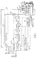
- engine 14 is shown as a central fuel injected engine having throttle body 18 coupled to intake manifold 20.
- Throttle body 18 is shown having throttle plate 24 positioned therein for controlling the induction of ambient air into intake manifold 20.
- Fuel injector 26 injects a predetermined amount of fuel into throttle body 18 in response to fuel controller 30.
- fuel controller 30 is controlled by both air/fuel feedback system 28 and fuel vapour control system 34.
- Fuel is delivered to fuel injector 26 by a conventional fuel system including fuel tank 32, fuel pump 36, and fuel rail 38.
- Fuel vapour recovery system 44 is shown coupled between fuel tank 32 and intake manifold 20 via purge line 46 and purge control valve 48.
- fuel vapour recovery system 44 includes vapour purge line 46 connected to fuel tank 32 and canister 56 which is connected in parallel to fuel tank 32 for absorbing fuel vapours therefrom by activated charcoal contained within the canister.
- purge control valve 48 is controlled by purge rate controller 52 to maintain a substantially constant flow of vapours therethrough regardless of the rate of air inducted into throttle body 18 or the manifold pressure of intake manifold 20.
- valve 48 is a pulse width actuated solenoid valve having constant cross-sectional area.
- a valve having a variable orifice may also be used to advantage such as a control valve supplied by SIEMENS as part no. F3DE-9C915-AA.
- sensors are shown coupled to engine 14 for providing indications of engine operation.
- these sensors include mass airflow sensor 64 which provides a measurement of mass airflow (MAF) inducted into engine 14.
- Manifold pressure sensor 68 provides a measurement (MAP) of absolute manifold pressure in intake manifold 20.
- Temperature sensor 70 provides a measurement of engine operating temperature (T).
- Throttle angle sensor 72 provides throttle position signal TA.
- Engine speed sensor 74 provides a measurement of engine speed (rpm) and crank angle (CA).
- Engine 14 also includes exhaust manifold 76 coupled to conventional 3-way (NO X , CO, HC) catalytic converter 78.
- Exhaust gas oxygen sensor 80 a conventional two-state oxygen sensor in this example, is shown coupled to exhaust manifold 76 for providing an indication of air/fuel ratio operation of engine 14. More specifically, exhaust gas oxygen sensor 80 provides a signal having a high state when air/fuel ratio operation is on the rich side of a predetermined air/fuel ratio commonly referred to as stoichiometry (14.7 lbs. air/lb. fuel in this particular example). When engine air/fuel ratio operation is lean of stoichiometry, exhaust gas oxygen sensor 80 provides its output signal at a low state.
- Air/fuel feedback system 28 is shown including LAMBSE controller 90 and base fuel controller 94.
- LAMBSE controller 90 a proportional plus integral controller in this particular example, integrates the output signal from exhaust gas oxygen sensor 80.
- the output control signal (LAMBSE) provided by LAMBSE controller 90 is at an average value of unity when engine 14 is operating at stoichiometry and there are no steady-state air/fuel errors or offsets. For a typical example of operation, LAMBSE ranges from 0.75-1.25.
- Base fuel controller 94 provides desired fuel charge signal Fd by dividing signal MAF by both LAMBSE and a reference or desired air/fuel ratio (A/F D ) such as stoichiometry as shown by the following equation.
- A/F D desired air/fuel ratio
- fuel vapour control system 34 provides output signal PCOMP representing a measurement of the mass flow of fuel vapours into intake manifold 20 during purge operation. More specifically, reference signal LAM R , unity in this particular example, is subtracted from signal LAMBSE to generate error signal LAM e . Integrator 112 integrates signal LAM e and provides an output to multiplier 116 for multiplication by a preselected scaling factor. Fuel vapour control system 34 is therefore a feedback air/fuel ratio controller responsive to fuel vapour purging and having a slower response time than air/fuel feedback system 28.
- the resulting signal PCOMP from multiplier 116 is subtracted from desired fuel signal Fd in summer 118 to generate modified desired fuel charge signal (Fdm).
- Fuel controller 30 converts signal Fdm into signal fpw having a pulse width directly correlated to signal Fdm.
- Fuel injector 26 is actuated during the pulse width of signal fpw such that the desired amount of fuel is metered into engine 14 for maintaining the desired air/fuel ratio (A/F D ).
- air/fuel feedback system 28 and fuel vapour control system 34 may be performed by a microcomputer in which case the functional blocks shown in Figure 1 are representative of program steps. These operations may also be performed by discrete IC's or analog circuitry.
- vapour purge is initiated at time t1.
- the rate of purge flow is gradually increased until it reaches the desired value at time t2.
- the desired rate of purge flow is a maximum wherein the duty cycle of signal ppw is 100%. Since the inducted mixture of air, fuel, purged fuel vapour, and purged air becomes richer as the purge flow is turned on, signal LAMBSE will gradually increase as purged fuel vapours are being inducted as shown between times t1 and t2 in Figure 2D.
- base fuel controller 94 In response to this increase in signal LAMBSE, base fuel controller 94 gradually decreases desired fuel charge signal Fd as shown in Figure 2B such that the overall actual air/fuel ratio of engine 14 remains, on average, at 14.7 (see Figure 2H). Stated another way, fuel delivered is decreased as fuel vapour is increased to maintain the desired air/fuel ratio.
- fuel vapour control system 34 provides signal PCOMP at a gradually increasing value as signal LAMBSE deviates from its reference value of unity. More specifically, as previously discussed herein, signal PCOMP is an integral of the difference between signal LAMBSE and its reference value of unity. It is seen that as signal PCOMP increases, the liquid fuel delivered (Fdm) to engine 14 is decreased such that signal LAMBSE is forced downward until an average value of unity is achieved at time t3. At this time, signal PCOMP reaches the value corresponding to the amount of purged fuel vapours.
- fuel vapour control system 34 adaptively learns the concentration of purged fuel vapours during a purge and compensates the overall engine air/fuel ratio for such purged fuel vapours.
- the operating range of authority of air/fuel feedback system 28 is therefore not reduced during fuel vapour purging. Any perturbation caused in engine air/fuel ratio by factors other than purged fuel vapours, such as perturbations in inducted airflow, are corrected by base fuel controller 94 in response to signal LAMBSE.
- desired fuel signal Fd provided by base fuel controller 94 increases in correlation with a decrease in signal LAMBSE until, at time t3, signal Fd reaches its value before introduction of purging.
- Fuel vapour control system 34 therefore essentially a measures the amount of fuel vapours purged during purging operations.
- base fuel controller 94 generates a desired fuel charge signal Fd representative of fuel required to maintain the desired engine air/fuel ratio independently of purging operations.
- LAMBSE controller 90 will detect this lean offset during the time interval from t4 through t5 and base fuel controller 94 will appropriately adjust the fuel delivered by time t5. However, an air/fuel transient occurs between times t4 and t5 as shown in Figure 2H due to the response time of LAMBSE controller 90.
- purge rate controller 52 Operation of purge rate controller 52 is now described in more detail with reference to Figure 3 and Figures 4A-4F.
- Desired purge flow signal Pfd is generated during step 162.
- signal Pfd is the maximum purge flow obtainable through purge control valve 48 (i.e., 100% duty cycle) to prevent emissions of hydrocarbons, operate engine 14 more efficiently, and reduce fuel system pressure.
- maximum purge flow is obtainable without exceeding the operating range of authority of air/fuel feedback system 28.
- signal Pfd is multiplied by a scaling factor shown as signal Mult.
- signal Mult is incremented in predetermined steps to a maximum value of unity for controlling the turn on of purge flow.
- the product Pfd * Mult is converted to the corresponding pulse width modulated signal ppw in step 166. For example, if signal Mult is 0.5, signal ppw is generated with a 50% duty cycle.
- step 170-174 purge is disabled under sudden deceleration conditions when there is an appreciable fuel vapour concentration to prevent temporary drivability problems. More specifically, a determination of whether fuel vapours comprise more than 70% of total fuel (fuel vapour plus liquid fuel) is made during step 170. In this particular example, signal PCOMP is divided by the sum of signal Fd plus signal PCOMP. If this ratio is greater than 70%, and the throttle position is less than 30/ (see step 172), then purge is disabled by setting signal Mult and signal PCOMP to zero (see step 174). However, if the ratio PCOMP/(Fdm + PCOMP) is less than 70%, or throttle position is greater than 30/, the process continues with step 180.
- step 180 and 182 signal Mult is decremented a predetermined amount if the fuel vapour contribution of total fuel is greater than 50%.
- the program is exited without further changes to signal Mult (see step 184) such that the rate of purge flow remains the same.
- fuel vapour concentration is less than 40% of total fuel, the program advances to step 90.
- steps 180-184 may be accomplished by other means. For example, a simple comparison of signal PCOMP to various preselected values may also be used to advantage for either decrementing purge flow during initiation of purging operations, or holding it constant, when there are high concentrations of fuel vapours.
- step 190 fuel injector pulse width signal fpw is compared to a first minimum value (min1) which defines an upper level of a pulse width dead band. If signal fpw is greater than min1, processing continues with program step 200. On the other hand, when signal fpw is less than min1, but greater than a minimum pulse width associated with the lower level of such dead band (min2), the rate of purge flow is not altered and the program exited (see step 192). Under such conditions the fuel injector pulse width signal fpw is within the dead band. However, when signal fpw is less than min2, the rate of purge flow is decremented a predetermined amount by decrementing signal Mult a corresponding predetermined amount (see steps 192 and 194).
- min1 a first minimum value
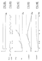
- purge flow is turned on at a gradual rate to its maximum value (i.e., signal Mult incremented to unity) when indications (EGO switching) are provided indicating that air/fuel feedback system 28 and fuel vapour control system 34 are properly compensating for purging of fuel vapours.
- signal LAMBSE The corresponding proportional plus integral operation of signal LAMBSE is shown in Figure 4E.
- Signal LAMBSE is shown first jumping upward due to its proportional term and then integrating upward after exhaust gas oxygen sensor 80 has switched at time t2.
- signal PCOMP is shown increasing as signal LAMBSE deviates from its reference value of unity.
- exhaust gas oxygen sensor 80 is shown switching lean in response to correction of delivered liquid fuel by both signal LAMBSE and signal PCOMP (see Figure 4B).
- purge flow is again incremented a predetermined amount. This operation continues with exhaust gas oxygen sensor switching at times t4, t5, t6, and t7 until the maximum rate of purge flow is achieved (i.e., signal ppw at 100% duty cycle).
- signal PCOMP adaptively learns the deviation in air/fuel ratio caused by induction of rich fuel vapours and forces signal LAMBSE back to its value before introduction of purge as shown at time t8 in Figures 4E and 4F. Accordingly, air/fuel feedback system 28 then has a full operating range of authority during purge operations unlike prior approaches. For illustrative purposes, operation indicative of prior approaches is shown by dashed lines in Figures 4D and 4E. The particular prior approaches indicated, which did not have any function similar to fuel vapour control system 34, inhibited the rate of purge flow when signal LAMBSE (or its functional equivalent) reached a value corresponding to the operating range of authority of the air/fuel feedback system. This limit is illustrated at time t5 in Figures 4D and 4E. Accordingly, such prior approaches may not maximise purge flow as does the invention herein described. A disadvantage of such approach is unnecessary emission of hydrocarbons into the atmosphere.
Landscapes
- Engineering & Computer Science (AREA)
- Chemical & Material Sciences (AREA)
- Combustion & Propulsion (AREA)
- Mechanical Engineering (AREA)
- General Engineering & Computer Science (AREA)
- Electrical Control Of Air Or Fuel Supplied To Internal-Combustion Engine (AREA)
- Supplying Secondary Fuel Or The Like To Fuel, Air Or Fuel-Air Mixtures (AREA)
Applications Claiming Priority (2)
| Application Number | Priority Date | Filing Date | Title |
|---|---|---|---|
| US07/622,651 US5048492A (en) | 1990-12-05 | 1990-12-05 | Air/fuel ratio control system and method for fuel vapor purging |
| US622651 | 1990-12-05 |
Publications (2)
| Publication Number | Publication Date |
|---|---|
| EP0489493A2 true EP0489493A2 (de) | 1992-06-10 |
| EP0489493A3 EP0489493A3 (en) | 1992-12-02 |
Family
ID=24494979
Family Applications (1)
| Application Number | Title | Priority Date | Filing Date |
|---|---|---|---|
| EP19910310064 Withdrawn EP0489493A3 (en) | 1990-12-05 | 1991-10-31 | Air/fuel ratio control system and method for fuel vapour purging |
Country Status (3)
| Country | Link |
|---|---|
| US (1) | US5048492A (de) |
| EP (1) | EP0489493A3 (de) |
| CA (1) | CA2052794C (de) |
Cited By (5)
| Publication number | Priority date | Publication date | Assignee | Title |
|---|---|---|---|---|
| EP0691469A1 (de) * | 1994-07-05 | 1996-01-10 | Regie Nationale Des Usines Renault S.A. | Verfahren zum steuern eines Innenverbrennungsmotors mit Tankentlüftungssystem |
| GB2370642A (en) * | 2000-08-15 | 2002-07-03 | Ford Global Tech Inc | Diagnosing a fuel tank condition |
| US8899209B2 (en) | 2010-10-08 | 2014-12-02 | Ford Global Technologies, Llc | System and method for compensating cetane |
| US8949002B2 (en) | 2012-02-21 | 2015-02-03 | Ford Global Technologies, Llc | System and method for injecting fuel |
| US9243580B2 (en) | 2011-12-07 | 2016-01-26 | Ford Global Technologies, Llc | Method and system for reducing soot formed by an engine |
Families Citing this family (35)
| Publication number | Priority date | Publication date | Assignee | Title |
|---|---|---|---|---|
| JPH0463937A (ja) * | 1990-06-29 | 1992-02-28 | Mazda Motor Corp | エンジンの制御装置 |
| JP2623937B2 (ja) * | 1990-08-08 | 1997-06-25 | トヨタ自動車株式会社 | 内燃機関の蒸発燃料処理制御装置 |
| JPH0586923A (ja) * | 1991-07-26 | 1993-04-06 | Nippon Soken Inc | 蒸発燃料パージ装置を有する内燃機関 |
| CA2077068C (en) * | 1991-10-03 | 1997-03-25 | Ken Ogawa | Control system for internal combustion engines |
| JP2920805B2 (ja) * | 1992-03-31 | 1999-07-19 | 本田技研工業株式会社 | 内燃機関の蒸発燃料制御装置 |
| JPH0610736A (ja) * | 1992-06-23 | 1994-01-18 | Nippondenso Co Ltd | 内燃機関の空燃比制御装置 |
| JP2658743B2 (ja) * | 1992-07-01 | 1997-09-30 | トヨタ自動車株式会社 | 内燃機関の空燃比制御装置 |
| US5465703A (en) * | 1992-07-09 | 1995-11-14 | Fuji Jukogyo Kabushiki Kaisha | Control method for purging fuel vapor of automotive engine |
| US5245978A (en) * | 1992-08-20 | 1993-09-21 | Ford Motor Company | Control system for internal combustion engines |
| US5224462A (en) * | 1992-08-31 | 1993-07-06 | Ford Motor Company | Air/fuel ratio control system for an internal combustion engine |
| JPH0693899A (ja) * | 1992-09-14 | 1994-04-05 | Nissan Motor Co Ltd | エンジンの蒸発燃料処理装置 |
| US5228421A (en) * | 1992-10-28 | 1993-07-20 | Ford Motor Company | Idle speed control system |
| US5203300A (en) * | 1992-10-28 | 1993-04-20 | Ford Motor Company | Idle speed control system |
| US5215055A (en) * | 1992-10-28 | 1993-06-01 | Ford Motor Company | Idle speed and fuel vapor recovery control system |
| JP3223605B2 (ja) * | 1992-11-10 | 2001-10-29 | 株式会社デンソー | 内燃機関の空燃比制御装置 |
| JP2819987B2 (ja) * | 1993-06-04 | 1998-11-05 | トヨタ自動車株式会社 | 内燃機関の空燃比制御装置 |
| US5520160A (en) * | 1993-08-26 | 1996-05-28 | Nippondenso Co., Ltd. | Fuel evaporative gas and air-fuel ratio control system |
| JPH07139440A (ja) * | 1993-11-18 | 1995-05-30 | Unisia Jecs Corp | エンジンの蒸発燃料処理装置 |
| US5366151A (en) * | 1993-12-27 | 1994-11-22 | Ford Motor Company | Hybrid vehicle fuel vapor management apparatus |
| JP3116718B2 (ja) * | 1994-04-22 | 2000-12-11 | トヨタ自動車株式会社 | 蒸発燃料処理装置 |
| JPH09324715A (ja) * | 1996-06-06 | 1997-12-16 | Toyota Motor Corp | 内燃機関の燃料供給装置 |
| JP2000018105A (ja) * | 1998-07-07 | 2000-01-18 | Nissan Motor Co Ltd | 内燃機関の制御装置 |
| DE19936166A1 (de) * | 1999-07-31 | 2001-02-08 | Bosch Gmbh Robert | Verfahren zum Betreiben einer Brennkraftmaschine insbesondere eines Kraftfahrzeugs |
| US6237328B1 (en) * | 1999-08-02 | 2001-05-29 | Ford Global Technologies, Inc. | Engine control with a fuel vapor purge system |
| US6192674B1 (en) * | 1999-08-02 | 2001-02-27 | Ford Global Technologies, Inc. | Heat generation method in an emission control device |
| US6256982B1 (en) * | 1999-08-02 | 2001-07-10 | Ford Global Technologies, Inc. | Fuel vapor purge for a direct injection engine |
| US6422214B1 (en) | 2000-08-15 | 2002-07-23 | Ford Global Technologies, Inc. | Fuel tank pressure control system |
| DE10138379B4 (de) * | 2000-08-12 | 2004-02-05 | Ford Global Technologies, LLC (n.d.Ges.d. Staates Delaware), Dearborn | Verfahren und Vorrichtung zur Zustandsdiagnose eines Kraftstofftanks |
| US6382191B1 (en) * | 2000-08-12 | 2002-05-07 | Ford Global Technologies, Inc. | Fuel tank pressure control system |
| US6595190B1 (en) | 2001-07-30 | 2003-07-22 | Ford Global Technologies, Llc | System and method for controlling release of fuel vapor from a vapor recovery system |
| US6651640B1 (en) | 2001-07-30 | 2003-11-25 | Ford Global Technologies, Llc | Vapor recovery purge system and method |
| US6778898B1 (en) | 2003-02-14 | 2004-08-17 | Ford Global Technologies, Llc | Computer controller for vehicle and engine system with carbon canister vapor storage |
| US7472015B2 (en) * | 2006-11-17 | 2008-12-30 | Gm Global Technology Operations, Inc. | Liquid fuel detection system |
| US9797322B2 (en) * | 2014-04-14 | 2017-10-24 | Ford Global Technologies, Llc | Method and system for fuel vapor management |
| KR20200069733A (ko) * | 2018-12-07 | 2020-06-17 | 현대자동차주식회사 | 연료 증발가스의 퍼지 제어방법 |
Family Cites Families (12)
| Publication number | Priority date | Publication date | Assignee | Title |
|---|---|---|---|---|
| JPS6065244A (ja) * | 1983-09-19 | 1985-04-15 | Toyota Motor Corp | 内燃機関の空燃比制御装置 |
| JPS611857A (ja) * | 1984-06-14 | 1986-01-07 | Toyota Motor Corp | 蒸発燃料処理装置 |
| JPS6176734A (ja) * | 1984-09-19 | 1986-04-19 | Mazda Motor Corp | エンジンの大気汚染防止装置 |
| US4677956A (en) * | 1985-07-19 | 1987-07-07 | Ford Motor Company | Solenoid duty cycle modulation for dynamic control of refueling vapor purge transient flow |
| US4932386A (en) * | 1985-07-26 | 1990-06-12 | Honda Giken Kogyo Kabushiki Kaisha | Fuel-vapor purge and air-fuel ratio control for automotive engine |
| US4641623A (en) * | 1985-07-29 | 1987-02-10 | Ford Motor Company | Adaptive feedforward air/fuel ratio control for vapor recovery purge system |
| JPH0726573B2 (ja) * | 1985-12-11 | 1995-03-29 | 富士重工業株式会社 | 自動車用エンジンの空燃比制御装置 |
| US4741318A (en) * | 1986-08-22 | 1988-05-03 | General Motors Corporation | Canister purge controller |
| US4841940A (en) * | 1987-04-07 | 1989-06-27 | Toyota Jidosha Kabushiki Kaisha | Air-fuel ratio control device of an internal combustion engine |
| US4748959A (en) * | 1987-05-04 | 1988-06-07 | Ford Motor Company | Regulation of engine parameters in response to vapor recovery purge systems |
| US4715340A (en) * | 1987-05-04 | 1987-12-29 | Ford Motor Company | Reduction of HC emissions for vapor recovery purge systems |
| JPS63190541U (de) * | 1987-05-27 | 1988-12-08 |
-
1990
- 1990-12-05 US US07/622,651 patent/US5048492A/en not_active Expired - Lifetime
-
1991
- 1991-10-04 CA CA002052794A patent/CA2052794C/en not_active Expired - Fee Related
- 1991-10-31 EP EP19910310064 patent/EP0489493A3/en not_active Withdrawn
Cited By (8)
| Publication number | Priority date | Publication date | Assignee | Title |
|---|---|---|---|---|
| EP0691469A1 (de) * | 1994-07-05 | 1996-01-10 | Regie Nationale Des Usines Renault S.A. | Verfahren zum steuern eines Innenverbrennungsmotors mit Tankentlüftungssystem |
| FR2722247A1 (fr) * | 1994-07-05 | 1996-01-12 | Renault Regie Nationale Usines | Procede de commande d'un moteur a combustion interne a recyclage de gaz de purge de l'event du reservoir |
| GB2370642A (en) * | 2000-08-15 | 2002-07-03 | Ford Global Tech Inc | Diagnosing a fuel tank condition |
| GB2370642B (en) * | 2000-08-15 | 2004-02-25 | Ford Global Tech Inc | Fuel tank pressure control system |
| US8899209B2 (en) | 2010-10-08 | 2014-12-02 | Ford Global Technologies, Llc | System and method for compensating cetane |
| US9506418B2 (en) | 2010-10-08 | 2016-11-29 | Ford Global Technologies, Llc | System and method for compensating cetane |
| US9243580B2 (en) | 2011-12-07 | 2016-01-26 | Ford Global Technologies, Llc | Method and system for reducing soot formed by an engine |
| US8949002B2 (en) | 2012-02-21 | 2015-02-03 | Ford Global Technologies, Llc | System and method for injecting fuel |
Also Published As
| Publication number | Publication date |
|---|---|
| US5048492A (en) | 1991-09-17 |
| EP0489493A3 (en) | 1992-12-02 |
| CA2052794A1 (en) | 1992-06-06 |
| CA2052794C (en) | 1999-05-04 |
Similar Documents
| Publication | Publication Date | Title |
|---|---|---|
| US5048492A (en) | Air/fuel ratio control system and method for fuel vapor purging | |
| EP0489489A2 (de) | Steuersystem für das Luft/Kraftstoff-Verhältnis einer Brennkraftmaschine | |
| EP0489490B1 (de) | Luft-/Kraftstoff-Verhältnissteuerung mit adaptivem Lernen der Entlüftung | |
| US5245978A (en) | Control system for internal combustion engines | |
| US4748959A (en) | Regulation of engine parameters in response to vapor recovery purge systems | |
| US7076943B2 (en) | System and method for determining set point location for oxidant-based engine air/fuel control strategy | |
| JP2694123B2 (ja) | 内燃機関の燃料タンク排気装置 | |
| US6964159B2 (en) | System and method for adjusting air/fuel ratio | |
| EP0415590A1 (de) | System zur Steuerung der Entlüftung von Kraftstoffdämpfen | |
| US5224462A (en) | Air/fuel ratio control system for an internal combustion engine | |
| GB2380434A (en) | A method for estimating a change in the amount of oxidants stored in the catalyst of an exhaust system. | |
| US7143574B2 (en) | System and method for determining set point location for oxidant-based engine air/fuel control strategy | |
| US5150686A (en) | Evaporative fuel control apparatus of internal combustion engine | |
| US5765541A (en) | Engine control system for a lean burn engine having fuel vapor recovery | |
| US5203300A (en) | Idle speed control system | |
| JPH06200842A (ja) | エンジンアイドル速度の制御方法とその装置 | |
| US5735255A (en) | Engine control system for a lean burn engine having fuel vapor recovery | |
| US6993899B2 (en) | System and method for controlling catalyst storage capacity | |
| US5396875A (en) | Air/fuel control with adaptively learned reference | |
| US5067469A (en) | Fuel vapor recovery system and method | |
| US4932386A (en) | Fuel-vapor purge and air-fuel ratio control for automotive engine | |
| GB2282679A (en) | IC engine control system | |
| EP0595584B1 (de) | System zur Steuerung der Leerlaufdrehzahl und der Kraftstoffdampf-Zurückgewinnung eines Verbrennungsmotors | |
| JPH04112959A (ja) | 蒸発燃料処理制御装置 |
Legal Events
| Date | Code | Title | Description |
|---|---|---|---|
| PUAI | Public reference made under article 153(3) epc to a published international application that has entered the european phase |
Free format text: ORIGINAL CODE: 0009012 |
|
| AK | Designated contracting states |
Kind code of ref document: A2 Designated state(s): DE FR GB |
|
| PUAL | Search report despatched |
Free format text: ORIGINAL CODE: 0009013 |
|
| AK | Designated contracting states |
Kind code of ref document: A3 Designated state(s): DE FR GB |
|
| 17P | Request for examination filed |
Effective date: 19930511 |
|
| 17Q | First examination report despatched |
Effective date: 19940210 |
|
| STAA | Information on the status of an ep patent application or granted ep patent |
Free format text: STATUS: THE APPLICATION HAS BEEN WITHDRAWN |
|
| 18W | Application withdrawn |
Withdrawal date: 19970315 |