EP0595728A1 - Système capteur pour système de freinage antiblocage - Google Patents
Système capteur pour système de freinage antiblocage Download PDFInfo
- Publication number
- EP0595728A1 EP0595728A1 EP19930402681 EP93402681A EP0595728A1 EP 0595728 A1 EP0595728 A1 EP 0595728A1 EP 19930402681 EP19930402681 EP 19930402681 EP 93402681 A EP93402681 A EP 93402681A EP 0595728 A1 EP0595728 A1 EP 0595728A1
- Authority
- EP
- European Patent Office
- Prior art keywords
- steering knuckle
- constant velocity
- velocity joint
- sensor
- probe
- Prior art date
- Legal status (The legal status is an assumption and is not a legal conclusion. Google has not performed a legal analysis and makes no representation as to the accuracy of the status listed.)
- Granted
Links
- 239000000523 sample Substances 0.000 claims description 48
- 238000000034 method Methods 0.000 claims description 16
- 239000002184 metal Substances 0.000 claims description 6
- 230000000694 effects Effects 0.000 claims description 5
- 238000009434 installation Methods 0.000 description 5
- 238000007789 sealing Methods 0.000 description 4
- 230000005355 Hall effect Effects 0.000 description 2
- 238000011109 contamination Methods 0.000 description 2
- 230000004888 barrier function Effects 0.000 description 1
- 230000005540 biological transmission Effects 0.000 description 1
- 239000000356 contaminant Substances 0.000 description 1
- 230000008878 coupling Effects 0.000 description 1
- 238000010168 coupling process Methods 0.000 description 1
- 238000005859 coupling reaction Methods 0.000 description 1
- 239000000314 lubricant Substances 0.000 description 1
- 239000012762 magnetic filler Substances 0.000 description 1
- 230000014759 maintenance of location Effects 0.000 description 1
- 239000000463 material Substances 0.000 description 1
- 238000012986 modification Methods 0.000 description 1
- 230000004048 modification Effects 0.000 description 1
- 229910052755 nonmetal Inorganic materials 0.000 description 1
- 238000003825 pressing Methods 0.000 description 1
- 238000005096 rolling process Methods 0.000 description 1
- 238000012358 sourcing Methods 0.000 description 1
- 238000009987 spinning Methods 0.000 description 1
- 239000000725 suspension Substances 0.000 description 1
Images


Classifications
-
- G—PHYSICS
- G01—MEASURING; TESTING
- G01M—TESTING STATIC OR DYNAMIC BALANCE OF MACHINES OR STRUCTURES; TESTING OF STRUCTURES OR APPARATUS, NOT OTHERWISE PROVIDED FOR
- G01M99/00—Subject matter not provided for in other groups of this subclass
-
- B—PERFORMING OPERATIONS; TRANSPORTING
- B60—VEHICLES IN GENERAL
- B60T—VEHICLE BRAKE CONTROL SYSTEMS OR PARTS THEREOF; BRAKE CONTROL SYSTEMS OR PARTS THEREOF, IN GENERAL; ARRANGEMENT OF BRAKING ELEMENTS ON VEHICLES IN GENERAL; PORTABLE DEVICES FOR PREVENTING UNWANTED MOVEMENT OF VEHICLES; VEHICLE MODIFICATIONS TO FACILITATE COOLING OF BRAKES
- B60T8/00—Arrangements for adjusting wheel-braking force to meet varying vehicular or ground-surface conditions, e.g. limiting or varying distribution of braking force
- B60T8/32—Arrangements for adjusting wheel-braking force to meet varying vehicular or ground-surface conditions, e.g. limiting or varying distribution of braking force responsive to a speed condition, e.g. acceleration or deceleration
- B60T8/321—Arrangements for adjusting wheel-braking force to meet varying vehicular or ground-surface conditions, e.g. limiting or varying distribution of braking force responsive to a speed condition, e.g. acceleration or deceleration deceleration
- B60T8/329—Systems characterised by their speed sensor arrangements
-
- B—PERFORMING OPERATIONS; TRANSPORTING
- B60—VEHICLES IN GENERAL
- B60T—VEHICLE BRAKE CONTROL SYSTEMS OR PARTS THEREOF; BRAKE CONTROL SYSTEMS OR PARTS THEREOF, IN GENERAL; ARRANGEMENT OF BRAKING ELEMENTS ON VEHICLES IN GENERAL; PORTABLE DEVICES FOR PREVENTING UNWANTED MOVEMENT OF VEHICLES; VEHICLE MODIFICATIONS TO FACILITATE COOLING OF BRAKES
- B60T8/00—Arrangements for adjusting wheel-braking force to meet varying vehicular or ground-surface conditions, e.g. limiting or varying distribution of braking force
- B60T8/17—Using electrical or electronic regulation means to control braking
- B60T8/171—Detecting parameters used in the regulation; Measuring values used in the regulation
-
- F—MECHANICAL ENGINEERING; LIGHTING; HEATING; WEAPONS; BLASTING
- F16—ENGINEERING ELEMENTS AND UNITS; GENERAL MEASURES FOR PRODUCING AND MAINTAINING EFFECTIVE FUNCTIONING OF MACHINES OR INSTALLATIONS; THERMAL INSULATION IN GENERAL
- F16C—SHAFTS; FLEXIBLE SHAFTS; ELEMENTS OR CRANKSHAFT MECHANISMS; ROTARY BODIES OTHER THAN GEARING ELEMENTS; BEARINGS
- F16C41/00—Other accessories, e.g. devices integrated in the bearing not relating to the bearing function as such
- F16C41/007—Encoders, e.g. parts with a plurality of alternating magnetic poles
-
- G—PHYSICS
- G01—MEASURING; TESTING
- G01P—MEASURING LINEAR OR ANGULAR SPEED, ACCELERATION, DECELERATION, OR SHOCK; INDICATING PRESENCE, ABSENCE, OR DIRECTION, OF MOVEMENT
- G01P3/00—Measuring linear or angular speed; Measuring differences of linear or angular speeds
- G01P3/42—Devices characterised by the use of electric or magnetic means
- G01P3/44—Devices characterised by the use of electric or magnetic means for measuring angular speed
- G01P3/443—Devices characterised by the use of electric or magnetic means for measuring angular speed mounted in bearings
-
- F—MECHANICAL ENGINEERING; LIGHTING; HEATING; WEAPONS; BLASTING
- F16—ENGINEERING ELEMENTS AND UNITS; GENERAL MEASURES FOR PRODUCING AND MAINTAINING EFFECTIVE FUNCTIONING OF MACHINES OR INSTALLATIONS; THERMAL INSULATION IN GENERAL
- F16C—SHAFTS; FLEXIBLE SHAFTS; ELEMENTS OR CRANKSHAFT MECHANISMS; ROTARY BODIES OTHER THAN GEARING ELEMENTS; BEARINGS
- F16C19/00—Bearings with rolling contact, for exclusively rotary movement
- F16C19/22—Bearings with rolling contact, for exclusively rotary movement with bearing rollers essentially of the same size in one or more circular rows, e.g. needle bearings
- F16C19/34—Bearings with rolling contact, for exclusively rotary movement with bearing rollers essentially of the same size in one or more circular rows, e.g. needle bearings for both radial and axial load
- F16C19/38—Bearings with rolling contact, for exclusively rotary movement with bearing rollers essentially of the same size in one or more circular rows, e.g. needle bearings for both radial and axial load with two or more rows of rollers
- F16C19/383—Bearings with rolling contact, for exclusively rotary movement with bearing rollers essentially of the same size in one or more circular rows, e.g. needle bearings for both radial and axial load with two or more rows of rollers with tapered rollers, i.e. rollers having essentially the shape of a truncated cone
- F16C19/385—Bearings with rolling contact, for exclusively rotary movement with bearing rollers essentially of the same size in one or more circular rows, e.g. needle bearings for both radial and axial load with two or more rows of rollers with tapered rollers, i.e. rollers having essentially the shape of a truncated cone with two rows, i.e. double-row tapered roller bearings
- F16C19/386—Bearings with rolling contact, for exclusively rotary movement with bearing rollers essentially of the same size in one or more circular rows, e.g. needle bearings for both radial and axial load with two or more rows of rollers with tapered rollers, i.e. rollers having essentially the shape of a truncated cone with two rows, i.e. double-row tapered roller bearings in O-arrangement
-
- F—MECHANICAL ENGINEERING; LIGHTING; HEATING; WEAPONS; BLASTING
- F16—ENGINEERING ELEMENTS AND UNITS; GENERAL MEASURES FOR PRODUCING AND MAINTAINING EFFECTIVE FUNCTIONING OF MACHINES OR INSTALLATIONS; THERMAL INSULATION IN GENERAL
- F16C—SHAFTS; FLEXIBLE SHAFTS; ELEMENTS OR CRANKSHAFT MECHANISMS; ROTARY BODIES OTHER THAN GEARING ELEMENTS; BEARINGS
- F16C2326/00—Articles relating to transporting
- F16C2326/01—Parts of vehicles in general
- F16C2326/02—Wheel hubs or castors
Definitions
- This invention relates generally to sensor systems and, more particularly, to sensor systems for determining the rotation of shafts and axles for vehicles and other applications.
- Antilock braking systems and traction control systems are now commonplace in the automotive marketplace and are standard equipment on many car models.
- the basis of these systems is a sensor system that senses wheel speed or rotation and relays that information to a controller
- the controller dictates, for example, the application of braking force intermittently to keep a respective wheel from skidding or slipping.
- Such use of the braking system allows vehicles to remain in control during maximum braking and to stop more efficiently.
- controllers can dictate the application of driving force for optimum traction.
- Non-integrated variable reluctance sensors often require adjustment after installation.
- Integrated hub assembly units require a large number of individual parts, introducing problems relating to inventory, installation and serviceability of those parts.
- Integrated spindle sensor bearings can limit an automotive manufacturer to a single supplier and may require new bearing designs to incorporate the sensor and encoder.
- a sensor system for antilock brakes and the like comprising an encoded target, target mounting means, and probe means.
- the target mounting means is adapted to be clamped between a constant velocity joint and a spindle bearing inner race, such that the encoded target rotates with a wheel spindle over which the spindle bearing inner race is mounted.
- the probe means is adapted to be mounted on a steering knuckle within which the constant velocity joint is mounted, such that the probe means senses the encoded target and generates a signal indicative of rotation of the wheel spindle.
- Figure 1 illustrates a portion of an automobile hub assembly 10 as might be used, for example, on a front wheel drive automobile equipped with antilock brakes.
- Hub assembly 10 includes wheel hub 12, wheel spindle 14, constant velocity joint 16, and steering knuckle 18.
- Steering knuckle 18 is supported by the automobile front suspension, not shown, for pivoting by a steering rack and pinion to effect steerage.
- Wheel spindle 14 is an extension of constant velocity joint 16 and is mounted in steering knuckle 18 by spindle bearing 20 for rotation relative to steering knuckle 18.
- Constant velocity joint 16 provides a universal (pivot) coupling to the automobile transmission and transmits power to wheel spindle 14 to effect rotation of a road wheel mounted on wheel hub 12.
- Spindle bearing 20 includes outer race 22, inner race 24, and rolling elements 26 between the races, and is provided with a spindle bearing seal 28 to retain lubricant and restrict entry of contaminants.
- Hub assembly 10 is equipped with a sensor system which includes a magnet subassembly 30 having a magnet 32, magnet carrier 34, and sensor seal 36.
- Sensor seal 36 serves as a "slinger” and is molded over magnet carrier 34 and a radially outward portion of magnet 32 to hold magnet 32 in place.
- Capturing cup 38 is a metal ring having a U-shaped cross section with its cylindrical middle portion mounted within counterbore surface 40 of steering knuckle 18. Capturing cup 38 is dimensioned such that the cylindrical middle portion is engaged by sensor seal 36 to effect sealing of the sensor system.
- Capturing cup 38 and magnet subassembly 30 are mounted on steering knuckle 18 before constant velocity joint 16 is installed in steering knuckle 18. Specifically, capturing cup 38 is press-fitted, for example, within counterbore surface 40 and subassembly 30 is held by engagement of sensor seal 36 with capturing cup 38 such that magnet carrier 34 is suspended radially inward. Constant velocity joint 16 is subsequently installed within steering knuckle 18 such that magnet carrier 34 pilots magnet subassembly 30 and a portion of subassembly 30 is clamped between constant velocity joint 16 and spindle bearing inner race 24.
- magnet carrier 34 is formed of metal by pressing, drawing, spinning or other convenient method and is configured with cone portion 42 conforming to an outer surface 44 of constant velocity joint 16. Radially inward edge of cone portion 42 is joined to radial face 46 of magnet carrier 34 that is received within an annular recess 48 in constant velocity joint 16. Magnet carrier 34 has an axially directed lip 50 at its radially outward edge for maintaining radial alignment of magnet 32 and for providing a key surface over which sensor seal 36 is molded.
- magnet carrier 34 is of a particular annular configuration in Figure 1, other mounting means may be employed with similar effect.
- magnet carrier 34 may take the form of a bracket with one or more fingers extending radially inwardly to be clamped between constant velocity joint 16 and spindle bearing inner race 24 by abutment with one of those two elements or by other clamping means.
- cone portion 42 other shapes may be used to guide magnet subassembly 30 into a desired position concentric to constant velocity joint 16 and wheel spindle 14.
- Sensor probe 52 is adapted to be mounted on steering knuckle 18 such that a sensor 54 therein is proximate to magnet 32 for sensing a magnetic field produced by magnet 32 and for generating a signal indicative of rotation of wheel spindle 14.
- Sensor 54 may be a Hall effect sensor or other known magnetic field sensing device.
- sensor probe 52 is located by a machined boss 56 and is inserted through an aperture 58 in a portion of steering knuckle 18 overlying constant velocity joint 16 and cone portion 42 of magnet carrier 34.
- Collar portion 60 overlies machined boss 56 on steering knuckle 18 to provide a stop surface for locating sensor 64 and to provide a barrier to contamination.
- Reduced diameter portion 64 extends through a counterbore of aperture 58 and terminates in a beveled end at sensor 54.
- O-rings 66 are received within the counterbore of aperture 58 to seal out contamination and to provide frictional retention.
- a bolt (not shown) securing collar portion 60 to steering knuckle 18, or other keying means, may be provided to drient the beveled end and sensor 54 with respect to magnet 32.
- Magnet subassembly 30 and sensor probe 52 can be removed to service spindle bearing 20 if necessary. Capturing cup 38 remains pressed in steering knuckle 18 and provides axial location of magnet carrier 34 and, also, a controlled surface for extending the life of sensor seal 36. Sensor probe 52 is highly serviceable since the probe can be removed simply by removing any securing bolt and pulling sensor probe 52 radially outwardly relative to constant velocity joint 16, in the axial direction of aperture 58.
- FIG. 2 illustrates a portion of an automobile hub assembly 70 including wheel hub 12, wheel spindle 14, constant velocity joint 16, and spindle bearing 20 common to those of hub assembly 10, described above.
- Hub assembly 70 is equipped with a sensor system which includes a magnet subassembly 72 comprising magnet 74 and a magnet carrier 76, and a spun-on cup 78 for securing magnet 74 to magnet carrier 76.
- Magnet carrier 76 has a cone shaped portion 80 and step portion 82 conforming to outer surface 44 of constant velocity joint 16.
- Capturing cup 84 comprising a cup ring 86 having an L-shaped cross section, sensor seal 88, and, radially facing bracket 90. Capturing cup 84 is dimensioned such that sensor seal 88 engages outer surface 44 of constant velocity joint 16. Sensor probe 92 is mounted in a slot within capturing cup 84 such that sensor 93 is proximate to magnet 74 to sense a magnetic field produced by magnet 74 to generate a signal indicative of rotation of wheel spindle 14. A resilient guide 94 may be formed in sensor probe 92 to ensure proper axial location of magnet 74. Sensor probe 92 is removable for service by removing capturing cup 84 over magnet subassembly 72 and withdrawing sensor probe 92 radially inwardly from the cup.
- Capturing cup 84 and magnet subassembly 30 are mounted on steering knuckle 96 before constant velocity joint 16 is installed. Specifically, capturing cup 84 is press-fitted or bolted, for example, within counterbore surface 98 and magnet subassembly 72 is held by engagement of sensor seal 88 such that magnet carrier 76 is suspended radially inward. constant velocity joint 16 is subsequently installed within steering knuckle 96 such that magnet carrier 76 pilots magnet subassembly 72 and a radially inwardly extending portion 100 is clamped between constant velocity joint 16 and spindle bearing inner race 24.
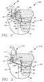
- Figure 3 illustrates a less serviceable embodiment of the present invention as installed within automobile hub assembly 110.
- This sensor system is less serviceable because removal of constant velocity joint 16 is required for replacement of sensor probe 112.
- Capturing cup 114 and magnet carrier 116 are similar to those described with respect to the embodiment of Figure 2.
- Capturing cup 114 includes a sensor seal 118 and is mounted on steering knuckle 120 in a manner similar to that of the second embodiment.
- sensor 122 of sensor probe 112 is positioned between magnet 124 and wheel spindle 14.
- Figure 4 illustrates an embodiment of the present invention installed within automobile hub assembly 130.
- Magnet 132 is secured to magnet carrier 134 by sensor seal 136 that is over-molded to form magnet subassembly 138.
- Magnet carrier 134 is pressed onto an annular groove 140 in an outer surface of constant velocity joint 142 before constant velocity joint 142 is installed into steering knuckle 144.
- Axially extending lip 146 on steering knuckle 144 provides a sealing surface for engagement with sensor seal 136.
- Sensor probe 148 is inserted through aperture 150 in steering knuckle 144 and secured by bolt 152, to be easily removable for service.
- Figure 5 illustrates a fifth embodiment of the present inventtion installed within automobile hub assembly 160.
- This sensor system is similar to that of Figure 1 with magnet subassembly 162 comprising magnet 164, magnet carrier 166 within annular recess 168 of constant velocity joint 170, and sensor seal 172 molded over magnet carrier 166.
- sensor seak 172 extends radially inward over cone portion 174 of magnet carrier 166 and extends radially outwardly as two sealing fingers 176.
- An additional outwardly extending lip 178 provides an interlock with multi-piece capturing cup 180, by entrapping a radially inwardly extending lip of capturing cup 180.
- capturing cup 180 and magnet subassembly 162 can be mounted as a single unit on steering knuckle 182 before installation of constant velocity joint 170 such that such that radially directed portion 184 is clamped between constant velocity joint 170 and inner race 24 in annular recess 186 of constant velocity joint 170.
- Sensor probe 186 is mounted on machined boss 188 of steering knuckle 184 by a bolt through hole 190 and may be sealed by O-rings 192. Again, Sensor probe 186 is easily removable for service by simply removing the bolt from hole 190 and withdrawing the probe radially outwardly with respect to constant velocity joint 170.
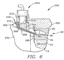
- FIG. 6 illustrates a sixth embodiment of the present invention installed within automobile hub assembly 200.
- Magnet subassembly 202 comprises magnet 204, magnet carrier 206, and sensor seal 208 with sealing fingers 210 similar to those of Figure 5.
- Sensor seal 208 interlocks with a radially inwardly extending lip of capturing cup 212.
- sensor probe 214 is mounted within a sensor mount 216 that is welded or otherwise fixed to capturing cup 212.
- sensor 218 of sensor probe 214 is radially aligned with respect to magnet 204 rather than axially aligned, as in the configurations of the other embodiments.
- a feature that may be considered a "one-piece” design.
- the probe, magnet subassembly, and capturing cup may be handled as a unit and installed on the respective steering knuckle together. This simplifies assembly by reducing the number of separate parts and steps required.
- sensor probe 214 can be inserted in sensor mount 216 of capturing cup 212 before capturing cup is press-fitted or otherwise mounted on steering knuckle 220. Note that this "one-piece" feature is in addition to the ability to remove sensor probe 214 from the sensor system for service.
- the magnets of these embodiments may be formed of a resilient rubber-like material with a magnetic filler and molded as a ring.
- a magnet of that type may be bonded to the magnet carrier.
- a suitable sensor probe for such magnet could be a Hall effect sensor.
- the present invention may employ other encoded targets and probe means.
- a variable reluctance sensor may be used with an encoded target comprising a toothed wheel or other form having alternating metal and non-metal portions.
- a magneto-resistive probe may also be used. However, some of these sensor probes may require more adjustment after installation than others.
- the present invention provides a sensor system for antilock brakes which solves the problems relating to adjustment, inventory, serviceability, sourcing and design requirements of prior designs.
- the sensor system disclosed herein is a stand alone sensing system for antilock braking systems and the like that minimizes the amount of modifications necessary to existing bearings and wheel spindles, is easily serviceable, and requires no adjustment after installation.
- Each of the illustrated embodiments uses an axially or radially oriented magnet, assembled to a formed piece of metal to provide a bracket that is fixed with respect to the rotatable wheel spindle.
Landscapes
- Engineering & Computer Science (AREA)
- Mechanical Engineering (AREA)
- Physics & Mathematics (AREA)
- General Physics & Mathematics (AREA)
- Transportation (AREA)
- General Engineering & Computer Science (AREA)
- Regulating Braking Force (AREA)
- Transmission And Conversion Of Sensor Element Output (AREA)
- Braking Arrangements (AREA)
Applications Claiming Priority (2)
| Application Number | Priority Date | Filing Date | Title |
|---|---|---|---|
| US07/969,659 US5287738A (en) | 1992-10-30 | 1992-10-30 | Sensor system for antilock brakes |
| US969659 | 1992-10-30 |
Publications (2)
| Publication Number | Publication Date |
|---|---|
| EP0595728A1 true EP0595728A1 (fr) | 1994-05-04 |
| EP0595728B1 EP0595728B1 (fr) | 1998-04-29 |
Family
ID=25515825
Family Applications (1)
| Application Number | Title | Priority Date | Filing Date |
|---|---|---|---|
| EP19930402681 Expired - Lifetime EP0595728B1 (fr) | 1992-10-30 | 1993-10-29 | Système capteur pour système de freinage antiblocage |
Country Status (11)
| Country | Link |
|---|---|
| US (1) | US5287738A (fr) |
| EP (1) | EP0595728B1 (fr) |
| JP (1) | JP3044312B2 (fr) |
| KR (1) | KR100208056B1 (fr) |
| CN (1) | CN1043440C (fr) |
| AR (1) | AR248457A1 (fr) |
| AU (1) | AU663453B2 (fr) |
| DE (1) | DE69318250T2 (fr) |
| ES (1) | ES2118920T3 (fr) |
| TW (1) | TW248547B (fr) |
| WO (1) | WO1994010549A1 (fr) |
Cited By (3)
| Publication number | Priority date | Publication date | Assignee | Title |
|---|---|---|---|---|
| DE4445610A1 (de) * | 1994-12-21 | 1996-06-27 | Kaco Gmbh Co | Dichtung |
| DE19745818C2 (de) * | 1996-10-16 | 2001-02-22 | Sabo Ind & Comercio Ltda | Dichtungsanordnung |
| EP1447240A3 (fr) * | 2003-02-17 | 2006-11-02 | Aktiebolaget SKF | Dispositif d'étanchéité pour un ensemble de moyeu de roue |
Families Citing this family (27)
| Publication number | Priority date | Publication date | Assignee | Title |
|---|---|---|---|---|
| FR2694082B1 (fr) * | 1992-07-23 | 1994-09-16 | Skf France | Codeur annulaire composite pour roulement et roulement à capteur d'informations, comportant un tel codeur. |
| US5291130A (en) * | 1993-01-25 | 1994-03-01 | Eaton Corporation | Vehicle wheel speed sensor employing an adaptable rotor cap |
| FR2717266B1 (fr) * | 1994-03-08 | 1996-04-19 | Roulements Soc Nouvelle | Dispositif de détection de la vitesse de rotation d'un palier de roulement. |
| US5510708A (en) * | 1994-10-20 | 1996-04-23 | General Motors Corporation | Variable reluctance rotation sensor with leakage magnetic flux sensing |
| FR2732421B1 (fr) * | 1995-03-28 | 1997-05-16 | Skf France | Roulement muni d'un dispositif integre de detection de la vitesse de rotation |
| DE19514801A1 (de) * | 1995-04-21 | 1996-10-24 | Wittur Aufzugteile Gmbh & Co | Verfahren zum Steuern und Überwachen des Betriebes einer Aufzugsanlage und Wälzlager zur Anwendung bei dem Verfahren |
| US5762425A (en) * | 1996-01-24 | 1998-06-09 | Nsk Ltd. | Rolling bearing unit with tachometer |
| JPH1123600A (ja) * | 1997-07-04 | 1999-01-29 | Nippon Seiko Kk | 回転速度検出装置付転がり軸受ユニット |
| JP3862453B2 (ja) * | 1999-09-10 | 2006-12-27 | Ntn株式会社 | 車輪軸受装置 |
| US6796404B1 (en) | 2000-03-22 | 2004-09-28 | American Axle & Manufacturing, Inc. | Cover pan ABS sensor |
| JP4857485B2 (ja) | 2001-04-25 | 2012-01-18 | 日本精工株式会社 | エンコーダ付車輪用回転支持装置 |
| JP2003120703A (ja) | 2001-10-16 | 2003-04-23 | Nsk Ltd | 回転検出装置付駆動輪用回転支持装置 |
| KR20040031252A (ko) * | 2002-10-04 | 2004-04-13 | 현대자동차주식회사 | 이물질 차단용 플렉시블 더스트커버 |
| US20060186627A1 (en) * | 2003-03-10 | 2006-08-24 | Katsura Koyagi | Axle-supporting device |
| DE10338960B4 (de) | 2003-08-25 | 2014-05-08 | Schaeffler Technologies Gmbh & Co. Kg | Dichtungsanordnung mit Encoder und Magnetisierungskopf für den Encoder |
| JP4691879B2 (ja) * | 2003-09-11 | 2011-06-01 | 日本精工株式会社 | 駆動輪用ハブユニット |
| DE102004048654A1 (de) * | 2004-10-06 | 2006-04-20 | Fag Kugelfischer Ag & Co. Ohg | Radlagereinheit mit einem in eine Dichtung integrierten Sensor |
| US20080159673A1 (en) * | 2005-01-27 | 2008-07-03 | Ntn Corporation | Vehicle Wheel Bearing Apparatus |
| JP2009275868A (ja) * | 2008-05-16 | 2009-11-26 | Ntn Corp | 回転速度検出装置付き車輪用軸受装置 |
| WO2009139179A1 (fr) * | 2008-05-16 | 2009-11-19 | Ntn株式会社 | Dispositif de palier d'essieu de véhicule doté d'un appareil de détection de vitesse de rotation |
| DE102009014923C5 (de) * | 2009-03-25 | 2015-07-23 | Ab Skf | Zweireihiges Kegelrollenlager, insbesondere zur Lagerung einer Rotorwelle einer Windkraftanlage |
| US8353390B2 (en) * | 2010-03-10 | 2013-01-15 | GM Global Technology Operations LLC | Splash shield for brake corner assembly |
| FR2966892B1 (fr) * | 2010-10-28 | 2013-08-09 | Peugeot Citroen Automobiles Sa | Dispositif de suspension de roue pour vehicule automobile a bague de protection du roulement de roue |
| IN2014MU00636A (fr) * | 2014-02-24 | 2015-10-23 | Mahindra & Mahindra Ltd | |
| KR101822856B1 (ko) * | 2016-02-22 | 2018-01-29 | 서한산업(주) | 실링 부재를 구비하는 차량용 액슬 어셈블리 |
| ITUA20162314A1 (it) * | 2016-04-05 | 2017-10-05 | Skf Ab | Gruppo cuscinetto-mozzo configurato per il montaggio al montante di una sospensione. |
| DE102018118880B4 (de) * | 2018-08-03 | 2025-05-28 | Schaeffler Technologies AG & Co. KG | Dichtungsanordnung eines Radlagers |
Citations (6)
| Publication number | Priority date | Publication date | Assignee | Title |
|---|---|---|---|---|
| US3927339A (en) * | 1971-12-07 | 1975-12-16 | Daimler Benz Ag | Frequency transmitters for producing control signals controlling the brake force in motor vehicle wheels |
| WO1987000290A1 (fr) * | 1985-07-01 | 1987-01-15 | Saab-Scania Aktiebolag | Agencement de fixation d'une roue-turbine a impulsion |
| DE3703395A1 (de) * | 1987-02-05 | 1988-08-18 | Porsche Ag | Rotor eines raddrehzahlfuehlers fuer antiblockiersysteme von kraftfahrzeugen |
| EP0357870A2 (fr) * | 1988-08-24 | 1990-03-14 | Rockwell International Corporation | Unité captrice de mesure de la vitesse de rotation |
| JPH04244966A (ja) * | 1991-01-31 | 1992-09-01 | Nissan Motor Co Ltd | アンチスキッド制御用車輪回転数センサの取付構造 |
| EP0522933A1 (fr) * | 1991-07-05 | 1993-01-13 | Skf France | Capteur de vitesse de rotation et palier à roulement équipé d'un tel capteur |
Family Cites Families (10)
| Publication number | Priority date | Publication date | Assignee | Title |
|---|---|---|---|---|
| US4954775A (en) * | 1986-03-03 | 1990-09-04 | Emhart Industries Inc. | Automotive wheel speed sensor assembly with multipole rotor mounted on wheel bearing spindle |
| US4904936A (en) * | 1986-03-03 | 1990-02-27 | Emhart Industries, Inc. | Automotive wheel speed sensor including ferromagnetic flux carrying cup closing an opening in the wheel bearing housing |
| US4969753A (en) * | 1987-05-29 | 1990-11-13 | Ntn Toyo Bearing Co., Ltd. | Wheel bearing assembly for automotive wheel |
| JP2633255B2 (ja) * | 1987-07-23 | 1997-07-23 | 光洋精工株式会社 | 車軸用軸受装置 |
| EP0397309A2 (fr) * | 1989-05-12 | 1990-11-14 | The Timken Company | Ensemble de palier |
| FR2653192B1 (fr) * | 1989-10-16 | 1995-01-20 | Roulements Soc Nouvelle | Roulement comportant un dispositif de detection de la vitesse. |
| US5157966A (en) * | 1990-02-20 | 1992-10-27 | The Torrington Company | Transmission speed sensor |
| AU620714B2 (en) * | 1990-02-20 | 1992-02-20 | Torrington Company, The | Transmission output speed sensor |
| US4988220A (en) * | 1990-05-14 | 1991-01-29 | General Motors Corporation | Servicable wheel speed sensor assembly |
| US5011302A (en) * | 1990-06-25 | 1991-04-30 | The Budd Company | Motor vehicle hub and bearing with integrated anti-lock brake sensor mounting |
-
1992
- 1992-10-30 US US07/969,659 patent/US5287738A/en not_active Expired - Lifetime
-
1993
- 1993-05-07 JP JP51102993A patent/JP3044312B2/ja not_active Expired - Lifetime
- 1993-05-07 WO PCT/US1993/004693 patent/WO1994010549A1/fr not_active Ceased
- 1993-05-07 AU AU43800/93A patent/AU663453B2/en not_active Expired
- 1993-05-07 KR KR1019940702273A patent/KR100208056B1/ko not_active Expired - Fee Related
- 1993-05-19 TW TW82103947A patent/TW248547B/zh active
- 1993-06-11 AR AR32515693A patent/AR248457A1/es active
- 1993-10-27 CN CN93119683A patent/CN1043440C/zh not_active Expired - Fee Related
- 1993-10-29 EP EP19930402681 patent/EP0595728B1/fr not_active Expired - Lifetime
- 1993-10-29 ES ES93402681T patent/ES2118920T3/es not_active Expired - Lifetime
- 1993-10-29 DE DE69318250T patent/DE69318250T2/de not_active Expired - Lifetime
Patent Citations (6)
| Publication number | Priority date | Publication date | Assignee | Title |
|---|---|---|---|---|
| US3927339A (en) * | 1971-12-07 | 1975-12-16 | Daimler Benz Ag | Frequency transmitters for producing control signals controlling the brake force in motor vehicle wheels |
| WO1987000290A1 (fr) * | 1985-07-01 | 1987-01-15 | Saab-Scania Aktiebolag | Agencement de fixation d'une roue-turbine a impulsion |
| DE3703395A1 (de) * | 1987-02-05 | 1988-08-18 | Porsche Ag | Rotor eines raddrehzahlfuehlers fuer antiblockiersysteme von kraftfahrzeugen |
| EP0357870A2 (fr) * | 1988-08-24 | 1990-03-14 | Rockwell International Corporation | Unité captrice de mesure de la vitesse de rotation |
| JPH04244966A (ja) * | 1991-01-31 | 1992-09-01 | Nissan Motor Co Ltd | アンチスキッド制御用車輪回転数センサの取付構造 |
| EP0522933A1 (fr) * | 1991-07-05 | 1993-01-13 | Skf France | Capteur de vitesse de rotation et palier à roulement équipé d'un tel capteur |
Cited By (4)
| Publication number | Priority date | Publication date | Assignee | Title |
|---|---|---|---|---|
| DE4445610A1 (de) * | 1994-12-21 | 1996-06-27 | Kaco Gmbh Co | Dichtung |
| DE19745818C2 (de) * | 1996-10-16 | 2001-02-22 | Sabo Ind & Comercio Ltda | Dichtungsanordnung |
| DE19745818C5 (de) * | 1996-10-16 | 2013-10-24 | Sabó Indústria e Comércio Ltda. | Dichtungsanordnung |
| EP1447240A3 (fr) * | 2003-02-17 | 2006-11-02 | Aktiebolaget SKF | Dispositif d'étanchéité pour un ensemble de moyeu de roue |
Also Published As
| Publication number | Publication date |
|---|---|
| KR100208056B1 (ko) | 1999-07-15 |
| EP0595728B1 (fr) | 1998-04-29 |
| AU663453B2 (en) | 1995-10-05 |
| WO1994010549A1 (fr) | 1994-05-11 |
| ES2118920T3 (es) | 1998-10-01 |
| DE69318250T2 (de) | 1998-12-17 |
| CN1043440C (zh) | 1999-05-19 |
| US5287738A (en) | 1994-02-22 |
| CN1088302A (zh) | 1994-06-22 |
| KR940703998A (ko) | 1994-12-12 |
| JP3044312B2 (ja) | 2000-05-22 |
| TW248547B (fr) | 1995-06-01 |
| AR248457A1 (es) | 1995-08-18 |
| AU4380093A (en) | 1994-05-24 |
| JPH07502824A (ja) | 1995-03-23 |
| DE69318250D1 (de) | 1998-06-04 |
Similar Documents
| Publication | Publication Date | Title |
|---|---|---|
| US5287738A (en) | Sensor system for antilock brakes | |
| EP0521693B1 (fr) | Montage à palier comprenant un capteur de vitesse et procédé pour son assemblage | |
| US6675640B2 (en) | Axle end wheel sensor for a vehicle, such as a truck or a trailer | |
| US5248939A (en) | Apparatus for sensing the direction and speed of a steering wheel shaft using hall effect sensors in a detachable sensor mounting | |
| CA1051108A (fr) | Dispositif a pose rapide pour relever la vitesse de rotation d'une roue de vehicule | |
| US5011302A (en) | Motor vehicle hub and bearing with integrated anti-lock brake sensor mounting | |
| EP0657738A1 (fr) | Joint d'étanchéité à codeur incorporé pour palier | |
| US5097701A (en) | Automobile wheel hub | |
| EP0767385B1 (fr) | Palier avec détecteur de vitesse de rotation à assemblage rapide | |
| JPH10260196A (ja) | 単列テーパ付ローラ軸受 | |
| EP2083186A1 (fr) | Protection de freinage | |
| EP1426257B1 (fr) | Capot protecteur pour un dispositif de roulement de roue | |
| EP0572734A1 (fr) | Ensemble de palier comprenant un capteur de vitesse de rotation | |
| US5739684A (en) | Unitarily formed hub and ABS exciter ring | |
| EP0507340B1 (fr) | Dispositif de moyeu avec un joint annulaire intégré d'un excitateur ABS | |
| KR20160122149A (ko) | 단차형 내륜을 포함하는 롤링 리벳 결합형 휠 베어링 장치 | |
| JP3973317B2 (ja) | 車輪軸受装置の製造方法 | |
| JPH0237065A (ja) | 自動車のアンチロックブレーキ装置用の転がり軸受ユニット | |
| JPS5851496B2 (ja) | 車輪速度感知器組立体 | |
| EP1591684A1 (fr) | Corps a ensemble sonde, dispositif de fermeture etanche, et dispositif a roulement a billes pour automobile | |
| US7194921B1 (en) | Speed-sensing device and method for assembling the same | |
| GB1566006A (en) | In-axle wheel speed sensor | |
| EP0578483A1 (fr) | Palier pour roues munies de capteurs de vitesse de rotation | |
| JP4116729B2 (ja) | 車輪軸受装置 | |
| JP2000162072A (ja) | ホイール用軸受 |
Legal Events
| Date | Code | Title | Description |
|---|---|---|---|
| PUAI | Public reference made under article 153(3) epc to a published international application that has entered the european phase |
Free format text: ORIGINAL CODE: 0009012 |
|
| AK | Designated contracting states |
Kind code of ref document: A1 Designated state(s): DE ES FR GB IT SE |
|
| 17P | Request for examination filed |
Effective date: 19940519 |
|
| 17Q | First examination report despatched |
Effective date: 19951017 |
|
| GRAG | Despatch of communication of intention to grant |
Free format text: ORIGINAL CODE: EPIDOS AGRA |
|
| GRAG | Despatch of communication of intention to grant |
Free format text: ORIGINAL CODE: EPIDOS AGRA |
|
| GRAH | Despatch of communication of intention to grant a patent |
Free format text: ORIGINAL CODE: EPIDOS IGRA |
|
| GRAH | Despatch of communication of intention to grant a patent |
Free format text: ORIGINAL CODE: EPIDOS IGRA |
|
| GRAA | (expected) grant |
Free format text: ORIGINAL CODE: 0009210 |
|
| AK | Designated contracting states |
Kind code of ref document: B1 Designated state(s): DE ES FR GB IT SE |
|
| REF | Corresponds to: |
Ref document number: 69318250 Country of ref document: DE Date of ref document: 19980604 |
|
| ET | Fr: translation filed | ||
| ITF | It: translation for a ep patent filed | ||
| PG25 | Lapsed in a contracting state [announced via postgrant information from national office to epo] |
Ref country code: SE Free format text: LAPSE BECAUSE OF FAILURE TO SUBMIT A TRANSLATION OF THE DESCRIPTION OR TO PAY THE FEE WITHIN THE PRESCRIBED TIME-LIMIT Effective date: 19980729 |
|
| REG | Reference to a national code |
Ref country code: ES Ref legal event code: FG2A Ref document number: 2118920 Country of ref document: ES Kind code of ref document: T3 |
|
| PLBE | No opposition filed within time limit |
Free format text: ORIGINAL CODE: 0009261 |
|
| STAA | Information on the status of an ep patent application or granted ep patent |
Free format text: STATUS: NO OPPOSITION FILED WITHIN TIME LIMIT |
|
| 26N | No opposition filed | ||
| REG | Reference to a national code |
Ref country code: GB Ref legal event code: IF02 |
|
| PGFP | Annual fee paid to national office [announced via postgrant information from national office to epo] |
Ref country code: FR Payment date: 20121031 Year of fee payment: 20 Ref country code: DE Payment date: 20121023 Year of fee payment: 20 |
|
| PGFP | Annual fee paid to national office [announced via postgrant information from national office to epo] |
Ref country code: ES Payment date: 20121026 Year of fee payment: 20 Ref country code: GB Payment date: 20121019 Year of fee payment: 20 Ref country code: IT Payment date: 20121026 Year of fee payment: 20 |
|
| REG | Reference to a national code |
Ref country code: DE Ref legal event code: R071 Ref document number: 69318250 Country of ref document: DE |
|
| REG | Reference to a national code |
Ref country code: DE Ref legal event code: R071 Ref document number: 69318250 Country of ref document: DE |
|
| REG | Reference to a national code |
Ref country code: GB Ref legal event code: PE20 Expiry date: 20131028 |
|
| PG25 | Lapsed in a contracting state [announced via postgrant information from national office to epo] |
Ref country code: GB Free format text: LAPSE BECAUSE OF EXPIRATION OF PROTECTION Effective date: 20131028 Ref country code: DE Free format text: LAPSE BECAUSE OF EXPIRATION OF PROTECTION Effective date: 20131030 |
|
| REG | Reference to a national code |
Ref country code: ES Ref legal event code: FD2A Effective date: 20140925 |
|
| PG25 | Lapsed in a contracting state [announced via postgrant information from national office to epo] |
Ref country code: ES Free format text: LAPSE BECAUSE OF EXPIRATION OF PROTECTION Effective date: 20131030 |