EP0595764A1 - Pompe à engrenages - Google Patents
Pompe à engrenages Download PDFInfo
- Publication number
- EP0595764A1 EP0595764A1 EP93810658A EP93810658A EP0595764A1 EP 0595764 A1 EP0595764 A1 EP 0595764A1 EP 93810658 A EP93810658 A EP 93810658A EP 93810658 A EP93810658 A EP 93810658A EP 0595764 A1 EP0595764 A1 EP 0595764A1
- Authority
- EP
- European Patent Office
- Prior art keywords
- gear pump
- inlet
- gear
- pump according
- extension
- Prior art date
- Legal status (The legal status is an assumption and is not a legal conclusion. Google has not performed a legal analysis and makes no representation as to the accuracy of the status listed.)
- Granted
Links
- 238000007872 degassing Methods 0.000 claims description 14
- 238000002156 mixing Methods 0.000 claims description 8
- 238000005086 pumping Methods 0.000 claims description 8
- 230000003068 static effect Effects 0.000 claims description 8
- 239000000155 melt Substances 0.000 claims description 2
- 229920003229 poly(methyl methacrylate) Polymers 0.000 claims description 2
- 229920000642 polymer Polymers 0.000 claims description 2
- 239000004926 polymethyl methacrylate Substances 0.000 claims description 2
- 230000007423 decrease Effects 0.000 claims 1
- 238000000605 extraction Methods 0.000 abstract 1
- 230000002349 favourable effect Effects 0.000 description 3
- 230000015572 biosynthetic process Effects 0.000 description 2
- 238000007599 discharging Methods 0.000 description 2
- 239000007788 liquid Substances 0.000 description 2
- 230000006978 adaptation Effects 0.000 description 1
- 239000000654 additive Substances 0.000 description 1
- 238000009835 boiling Methods 0.000 description 1
- 230000001419 dependent effect Effects 0.000 description 1
- 238000011161 development Methods 0.000 description 1
- 230000018109 developmental process Effects 0.000 description 1
- 239000000178 monomer Substances 0.000 description 1
- 239000004033 plastic Substances 0.000 description 1
- 229920003023 plastic Polymers 0.000 description 1
- 239000002904 solvent Substances 0.000 description 1
Images



Classifications
-
- F—MECHANICAL ENGINEERING; LIGHTING; HEATING; WEAPONS; BLASTING
- F04—POSITIVE - DISPLACEMENT MACHINES FOR LIQUIDS; PUMPS FOR LIQUIDS OR ELASTIC FLUIDS
- F04C—ROTARY-PISTON, OR OSCILLATING-PISTON, POSITIVE-DISPLACEMENT MACHINES FOR LIQUIDS; ROTARY-PISTON, OR OSCILLATING-PISTON, POSITIVE-DISPLACEMENT PUMPS
- F04C15/00—Component parts, details or accessories of machines, pumps or pumping installations, not provided for in groups F04C2/00 - F04C14/00
- F04C15/06—Arrangements for admission or discharge of the working fluid, e.g. constructional features of the inlet or outlet
-
- F—MECHANICAL ENGINEERING; LIGHTING; HEATING; WEAPONS; BLASTING
- F04—POSITIVE - DISPLACEMENT MACHINES FOR LIQUIDS; PUMPS FOR LIQUIDS OR ELASTIC FLUIDS
- F04C—ROTARY-PISTON, OR OSCILLATING-PISTON, POSITIVE-DISPLACEMENT MACHINES FOR LIQUIDS; ROTARY-PISTON, OR OSCILLATING-PISTON, POSITIVE-DISPLACEMENT PUMPS
- F04C13/00—Adaptations of machines or pumps for special use, e.g. for extremely high pressures
- F04C13/001—Pumps for particular liquids
- F04C13/002—Pumps for particular liquids for homogeneous viscous liquids
Definitions
- the invention relates to a gear pump according to the preamble of claim 1.
- the invention further relates to pump systems with such a gear pump and to the use of the gear pump, in particular for discharging highly viscous media from a vacuum against a high delivery pressure.
- the enlargement in the inlet can extend up to the level of the gearwheel axes, and the length R of the enlargement can be at least 10% greater than the length D of the gear pair.
- the enlargement of the inlet area can have a width C in the gearwheels which is larger than the tooth width T, for example by at least 10%.
- Favorable inlet geometries can be further achieved by a ratio of inlet diameter B to inlet depth L of at least 2 and by a ratio of extension length R to inlet depth L, which is greater than 1.85.
- a funnel-shaped inlet area can advantageously have an opening angle W of at least 55 °.
- a cost-effective modular design with pumps according to the invention is possible by, for example, different tooth sizes with an adapted inlet area in the same housing and outlet diameter can be used.
- the outlet diameter A can be set appropriately using an insert sleeve.
- a particularly powerful pumping and mixing system is formed with a gear pump according to the invention combined with a downstream static mixing element.
- a simple and efficient pumping and degassing system is formed with a gear pump according to the invention combined with a degassing chamber for the discharge of highly viscous media from the degassing chamber with high delivery pressure.
- the gear pump 1 has an inlet 4, an outlet 6 and a pair of gearwheels 2 in a housing 3.
- the inlet 4 has an extension 10 which extends down to the plane 11 of the gearwheel axes 12.
- 1c shows the cross-sectional area FZ of the gear wheels 2, in the form of a rectangle D x T with length D and width T of the gear pair.
- the extension 10 with the cross-sectional area FE has a length R and a width C.
- the shape of the extension is made up of funnel-shaped or conical and flat boundary surfaces.
- the funnel-shaped part of the inlet has an opening angle W, with an inlet diameter D in the upper flange plane 14.
- the cross-sectional area FE of the extension (in the region of the gearwheel axes) is larger than that of the gearwheels FZ and the diagonal D3 is in accordance with claim 1
- Gear cross-sectional area FZ is always smaller than the inlet diameter B.
- both the length R and the width C of the extension FE are greater than the corresponding length D and the width T of the gear cross-sectional area FZ.
- FIG. 3 and 4 show further examples of cross-sectional areas FE.
- the cross-sectional area 32 in FIG. 3 is likewise rectangular like the gearwheel cross-sectional area FZ.
- the cross-sectional area 33 of FIG. 4 shows, as a further advantageous example, a rounded, crescent-shaped extension 33 in the area of the external teeth of the gear pair 2.
- the cross-sectional area FA is also shown in FIG. 4, which is formed by the center distance Z and tooth width T.
- the outlet diameter A should then essentially correspond to the diagonal D4 of this cross-sectional area FA.
- the ratio of outlet diameter A to Diagonal D4 is preferably in the range 0.9 to 1.1.
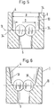
- FIG. 5 and 6 show further examples of the vertical course of the extension 10.
- the extension 10 first runs vertically downward and then bends into the axis plane 11 with a curve 34.
- the extension 10 tapers, delimited by the offset oblique planes 35, to the axis plane 11.
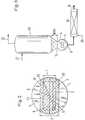
- FIG. 8 shows a system for pumping, mixing and degassing polymer melts, for example of PE, PS or PMMA, with an inlet 21, a degassing chamber 25, a pump 1 according to the invention, which pumps into a static mixing element 20 and with an outlet 24 a vapor outlet 22, solvents and monomers are removed from the degassing chamber 25.
- Additives 26, for example, can be added to the mixer 20 via a further access be fed.
Landscapes
- Engineering & Computer Science (AREA)
- Mechanical Engineering (AREA)
- General Engineering & Computer Science (AREA)
- Rotary Pumps (AREA)
- Details And Applications Of Rotary Liquid Pumps (AREA)
Applications Claiming Priority (2)
| Application Number | Priority Date | Filing Date | Title |
|---|---|---|---|
| CH337992 | 1992-10-29 | ||
| CH3379/92 | 1992-10-29 |
Publications (2)
| Publication Number | Publication Date |
|---|---|
| EP0595764A1 true EP0595764A1 (fr) | 1994-05-04 |
| EP0595764B1 EP0595764B1 (fr) | 1997-10-29 |
Family
ID=4254688
Family Applications (1)
| Application Number | Title | Priority Date | Filing Date |
|---|---|---|---|
| EP93810658A Expired - Lifetime EP0595764B1 (fr) | 1992-10-29 | 1993-09-20 | Pompe à engrenages |
Country Status (5)
| Country | Link |
|---|---|
| US (1) | US5388974A (fr) |
| EP (1) | EP0595764B1 (fr) |
| JP (1) | JPH06200881A (fr) |
| DE (1) | DE59307598D1 (fr) |
| ES (1) | ES2110077T3 (fr) |
Cited By (3)
| Publication number | Priority date | Publication date | Assignee | Title |
|---|---|---|---|---|
| DE19717295A1 (de) * | 1997-04-24 | 1998-10-29 | Danfoss As | Fluid-Maschine |
| DE19635706C2 (de) * | 1996-09-03 | 1998-12-03 | Andreas Prof Dr Limper | Verfahren zum Plastifizieren, Sieben, Dosieren und Fördern hochviskoser Kautschukmischungen und Einrichtung für die Durchführung des Verfahrens |
| DE19825650C2 (de) * | 1998-06-09 | 2001-03-01 | Danfoss As | Schmierölversorgungseinrichtung für ein Gerät mit rotierender Gerätewelle |
Families Citing this family (9)
| Publication number | Priority date | Publication date | Assignee | Title |
|---|---|---|---|---|
| JPH11247767A (ja) * | 1997-12-23 | 1999-09-14 | Maag Pump Syst Textron Ag | 歯車ポンプの軸を位置決めするための方法および歯車ポンプ |
| CA2343238C (fr) * | 1998-10-01 | 2007-07-10 | The Dow Chemical Company | Pompe a engrenages tres efficace permettant de pomper des liquides a tres forte viscosite |
| DE102007011644B4 (de) * | 2006-03-10 | 2016-01-14 | Robert Bosch Gmbh | Hydrostatische Kolbenmaschine in Axialkolbenbauweise mit einem Kombi-Pumpengehäuse für mehrere Triebwerks Nenngrößen und verschiedene Hilfspumpen |
| DE102006058355A1 (de) * | 2006-03-10 | 2007-09-13 | Brueninghaus Hydromatik Gmbh | Kombi-Pumpengehäuse für mehrere Nenngrößen |
| DE202009012158U1 (de) * | 2009-09-08 | 2011-02-03 | Hugo Vogelsang Maschinenbau Gmbh | Drehkolbenpumpe |
| DE202010011626U1 (de) | 2010-08-20 | 2010-10-21 | Hugo Vogelsang Maschinenbau Gmbh | Drehkolbenpumpe |
| US20140323792A1 (en) * | 2013-04-25 | 2014-10-30 | Mp Associates, Inc. | Desensitizing explosive materials using a vacuum vessel |
| KR101704368B1 (ko) * | 2013-10-01 | 2017-02-07 | 마아크펌프시스템즈아게 | 개선된 펌프 유입구를 가지는 기어 펌프 |
| US11378076B1 (en) * | 2021-01-28 | 2022-07-05 | Shimadzu Corporation | Gear pump or motor |
Citations (3)
| Publication number | Priority date | Publication date | Assignee | Title |
|---|---|---|---|---|
| US2531726A (en) * | 1946-01-26 | 1950-11-28 | Roper Corp Geo D | Positive displacement rotary pump |
| US4137023A (en) * | 1975-09-03 | 1979-01-30 | Union Carbide Corporation | Low energy recovery compounding and fabricating apparatus for plastic materials |
| EP0189670A1 (fr) * | 1985-01-05 | 1986-08-06 | Maag Pump Systems AG | Pompes à engrenage |
Family Cites Families (4)
| Publication number | Priority date | Publication date | Assignee | Title |
|---|---|---|---|---|
| FR1073834A (fr) * | 1952-04-02 | 1954-09-29 | Daimler Benz Ag | Compresseur à piston rotatif, en particulier compresseur root pour moteurs à combustion interne |
| DE1941673A1 (de) * | 1969-08-16 | 1971-02-18 | Barmag Barmer Maschf | Zahnradpumpe mit keilfoermig verjuengten Einzugskammern |
| US3837768A (en) * | 1973-08-31 | 1974-09-24 | Maag Zahnraeder & Maschinen Ag | Gear pump for highly viscous media |
| US4737087A (en) * | 1984-12-10 | 1988-04-12 | Barmag Ag | Drive shaft seal for gear pump and method |
-
1993
- 1993-09-20 EP EP93810658A patent/EP0595764B1/fr not_active Expired - Lifetime
- 1993-09-20 DE DE59307598T patent/DE59307598D1/de not_active Expired - Fee Related
- 1993-09-20 ES ES93810658T patent/ES2110077T3/es not_active Expired - Lifetime
- 1993-10-12 US US08/134,776 patent/US5388974A/en not_active Expired - Fee Related
- 1993-10-20 JP JP5262743A patent/JPH06200881A/ja active Pending
Patent Citations (3)
| Publication number | Priority date | Publication date | Assignee | Title |
|---|---|---|---|---|
| US2531726A (en) * | 1946-01-26 | 1950-11-28 | Roper Corp Geo D | Positive displacement rotary pump |
| US4137023A (en) * | 1975-09-03 | 1979-01-30 | Union Carbide Corporation | Low energy recovery compounding and fabricating apparatus for plastic materials |
| EP0189670A1 (fr) * | 1985-01-05 | 1986-08-06 | Maag Pump Systems AG | Pompes à engrenage |
Cited By (4)
| Publication number | Priority date | Publication date | Assignee | Title |
|---|---|---|---|---|
| DE19635706C2 (de) * | 1996-09-03 | 1998-12-03 | Andreas Prof Dr Limper | Verfahren zum Plastifizieren, Sieben, Dosieren und Fördern hochviskoser Kautschukmischungen und Einrichtung für die Durchführung des Verfahrens |
| DE19717295A1 (de) * | 1997-04-24 | 1998-10-29 | Danfoss As | Fluid-Maschine |
| DE19717295C2 (de) * | 1997-04-24 | 1999-09-23 | Danfoss As | Fluid-Maschine |
| DE19825650C2 (de) * | 1998-06-09 | 2001-03-01 | Danfoss As | Schmierölversorgungseinrichtung für ein Gerät mit rotierender Gerätewelle |
Also Published As
| Publication number | Publication date |
|---|---|
| US5388974A (en) | 1995-02-14 |
| ES2110077T3 (es) | 1998-02-01 |
| JPH06200881A (ja) | 1994-07-19 |
| DE59307598D1 (de) | 1997-12-04 |
| EP0595764B1 (fr) | 1997-10-29 |
Similar Documents
| Publication | Publication Date | Title |
|---|---|---|
| EP0595764B1 (fr) | Pompe à engrenages | |
| DE3153250C2 (de) | Hydraulisches Grubenförderungsverfahren | |
| WO2007118788A1 (fr) | Procédé en continu pour conduire une réaction chimique dans laquelle une phase gazeuse est ajoutée à un flux de départ contenant une ou plusieurs phases solides dissoutes ou dispersées dans de l'eau | |
| DE2736153A1 (de) | Filter- und mischeinrichtung zur vermischung von schmieroel und kraftstoff | |
| EP2710896B1 (fr) | Dispositif d'acheminement de produits alimentaires et procédé d'acheminement d'un produit alimentaire | |
| EP2022760B1 (fr) | Cartouche de filtre pour un dispositif de filtre à eau | |
| DE19856298C1 (de) | Vorrichtung zum Fördern von Kraftstoff aus einem Vorratsbehälter zur Brennkraftmaschine eines Kraftfahrzeuges | |
| DE2556169C3 (de) | Impulsgesteuerte Tropfenspritzeinrichtung | |
| EP1165965B1 (fr) | Compresseur a conduit lateral | |
| DE602005004294T2 (de) | Dosiervorrichtung zum einführen eines additivs in einen flüssigkeitsstrom | |
| DE69303447T2 (de) | Vakuumpumpgerät | |
| DE68918864T2 (de) | Gerät zum Einspritzen eines Zusatzstoffes in eine Flüssigkeit. | |
| DE10119349A1 (de) | Vorrichtung zur Unterstützung eines Absaugvorgangs sowie Absauganlage und Absaugverfahren | |
| EP3767105B1 (fr) | Stator pour une pompe à vis sans fin excentrique | |
| DE3424787C2 (fr) | ||
| WO2001052966A1 (fr) | Dispositif filtre | |
| DE69002439T2 (de) | Verfahren zum Betrieb einer volumetrischen Pumpe. | |
| DE10018348A1 (de) | Zahnradpumpe, insbesondere für eine Hochdruck-Kraftstoffpumpe | |
| DE10020089B4 (de) | Verfahren und Vorrichtung zum dosierten Einbringen eines Flüssigkeitsvolumenstroms in ein System | |
| DE102021105727A1 (de) | Kreiselpumpe mit Einlaufrippen | |
| DE2325098C3 (de) | Entleerungsvorrichtung für einen Schachtofen | |
| DE2523855C3 (de) | Einrichtung zur Kompression eines reaktiven Gases | |
| DE69321537T2 (de) | Passiver Inline-Membranentgaser | |
| DD138056B1 (de) | Vorrichtung zum pneumatischen transport,insbesondere fuer schwer fliessende,stark schleissende oder explosive schuettgueter | |
| EP0710625B1 (fr) | Dispositif et procédé pour la floculation de suspensions |
Legal Events
| Date | Code | Title | Description |
|---|---|---|---|
| PUAI | Public reference made under article 153(3) epc to a published international application that has entered the european phase |
Free format text: ORIGINAL CODE: 0009012 |
|
| AK | Designated contracting states |
Kind code of ref document: A1 Designated state(s): BE CH DE ES FR GB IT LI NL SE |
|
| 17P | Request for examination filed |
Effective date: 19941007 |
|
| 17Q | First examination report despatched |
Effective date: 19951117 |
|
| GRAG | Despatch of communication of intention to grant |
Free format text: ORIGINAL CODE: EPIDOS AGRA |
|
| GRAH | Despatch of communication of intention to grant a patent |
Free format text: ORIGINAL CODE: EPIDOS IGRA |
|
| GRAH | Despatch of communication of intention to grant a patent |
Free format text: ORIGINAL CODE: EPIDOS IGRA |
|
| GRAA | (expected) grant |
Free format text: ORIGINAL CODE: 0009210 |
|
| AK | Designated contracting states |
Kind code of ref document: B1 Designated state(s): BE CH DE ES FR GB IT LI NL SE |
|
| REG | Reference to a national code |
Ref country code: CH Ref legal event code: NV Representative=s name: SULZER MANAGEMENT AG Ref country code: CH Ref legal event code: EP |
|
| GBT | Gb: translation of ep patent filed (gb section 77(6)(a)/1977) |
Effective date: 19971031 |
|
| REF | Corresponds to: |
Ref document number: 59307598 Country of ref document: DE Date of ref document: 19971204 |
|
| ITF | It: translation for a ep patent filed | ||
| ET | Fr: translation filed | ||
| REG | Reference to a national code |
Ref country code: ES Ref legal event code: FG2A Ref document number: 2110077 Country of ref document: ES Kind code of ref document: T3 |
|
| PLBE | No opposition filed within time limit |
Free format text: ORIGINAL CODE: 0009261 |
|
| STAA | Information on the status of an ep patent application or granted ep patent |
Free format text: STATUS: NO OPPOSITION FILED WITHIN TIME LIMIT |
|
| 26N | No opposition filed | ||
| REG | Reference to a national code |
Ref country code: GB Ref legal event code: IF02 |
|
| PGFP | Annual fee paid to national office [announced via postgrant information from national office to epo] |
Ref country code: GB Payment date: 20030827 Year of fee payment: 11 |
|
| PGFP | Annual fee paid to national office [announced via postgrant information from national office to epo] |
Ref country code: NL Payment date: 20030828 Year of fee payment: 11 |
|
| PGFP | Annual fee paid to national office [announced via postgrant information from national office to epo] |
Ref country code: SE Payment date: 20030901 Year of fee payment: 11 Ref country code: CH Payment date: 20030901 Year of fee payment: 11 |
|
| PGFP | Annual fee paid to national office [announced via postgrant information from national office to epo] |
Ref country code: DE Payment date: 20030903 Year of fee payment: 11 |
|
| PGFP | Annual fee paid to national office [announced via postgrant information from national office to epo] |
Ref country code: FR Payment date: 20030904 Year of fee payment: 11 |
|
| PGFP | Annual fee paid to national office [announced via postgrant information from national office to epo] |
Ref country code: ES Payment date: 20030919 Year of fee payment: 11 |
|
| PGFP | Annual fee paid to national office [announced via postgrant information from national office to epo] |
Ref country code: BE Payment date: 20031001 Year of fee payment: 11 |
|
| PG25 | Lapsed in a contracting state [announced via postgrant information from national office to epo] |
Ref country code: GB Free format text: LAPSE BECAUSE OF NON-PAYMENT OF DUE FEES Effective date: 20040920 |
|
| PG25 | Lapsed in a contracting state [announced via postgrant information from national office to epo] |
Ref country code: SE Free format text: LAPSE BECAUSE OF NON-PAYMENT OF DUE FEES Effective date: 20040921 Ref country code: ES Free format text: LAPSE BECAUSE OF NON-PAYMENT OF DUE FEES Effective date: 20040921 |
|
| PG25 | Lapsed in a contracting state [announced via postgrant information from national office to epo] |
Ref country code: LI Free format text: LAPSE BECAUSE OF NON-PAYMENT OF DUE FEES Effective date: 20040930 Ref country code: CH Free format text: LAPSE BECAUSE OF NON-PAYMENT OF DUE FEES Effective date: 20040930 Ref country code: BE Free format text: LAPSE BECAUSE OF NON-PAYMENT OF DUE FEES Effective date: 20040930 |
|
| BERE | Be: lapsed |
Owner name: *SULZER CHEMTECH A.G. Effective date: 20040930 |
|
| PG25 | Lapsed in a contracting state [announced via postgrant information from national office to epo] |
Ref country code: NL Free format text: LAPSE BECAUSE OF NON-PAYMENT OF DUE FEES Effective date: 20050401 Ref country code: DE Free format text: LAPSE BECAUSE OF NON-PAYMENT OF DUE FEES Effective date: 20050401 |
|
| EUG | Se: european patent has lapsed | ||
| GBPC | Gb: european patent ceased through non-payment of renewal fee |
Effective date: 20040920 |
|
| REG | Reference to a national code |
Ref country code: CH Ref legal event code: PL |
|
| PG25 | Lapsed in a contracting state [announced via postgrant information from national office to epo] |
Ref country code: FR Free format text: LAPSE BECAUSE OF NON-PAYMENT OF DUE FEES Effective date: 20050531 |
|
| NLV4 | Nl: lapsed or anulled due to non-payment of the annual fee |
Effective date: 20050401 |
|
| REG | Reference to a national code |
Ref country code: FR Ref legal event code: ST |
|
| PG25 | Lapsed in a contracting state [announced via postgrant information from national office to epo] |
Ref country code: IT Free format text: LAPSE BECAUSE OF NON-PAYMENT OF DUE FEES;WARNING: LAPSES OF ITALIAN PATENTS WITH EFFECTIVE DATE BEFORE 2007 MAY HAVE OCCURRED AT ANY TIME BEFORE 2007. THE CORRECT EFFECTIVE DATE MAY BE DIFFERENT FROM THE ONE RECORDED. Effective date: 20050920 |
|
| REG | Reference to a national code |
Ref country code: ES Ref legal event code: FD2A Effective date: 20040921 |
|
| BERE | Be: lapsed |
Owner name: *SULZER CHEMTECH A.G. Effective date: 20040930 |