EP0596111A1 - Procede d'alimentation en catalyseur d'un lit fluidise pour proceder a une polymerisation en phase vapeur - Google Patents
Procede d'alimentation en catalyseur d'un lit fluidise pour proceder a une polymerisation en phase vapeur Download PDFInfo
- Publication number
- EP0596111A1 EP0596111A1 EP91913082A EP91913082A EP0596111A1 EP 0596111 A1 EP0596111 A1 EP 0596111A1 EP 91913082 A EP91913082 A EP 91913082A EP 91913082 A EP91913082 A EP 91913082A EP 0596111 A1 EP0596111 A1 EP 0596111A1
- Authority
- EP
- European Patent Office
- Prior art keywords
- catalyst
- pipe
- feeding
- fluidized bed
- reactor
- Prior art date
- Legal status (The legal status is an assumption and is not a legal conclusion. Google has not performed a legal analysis and makes no representation as to the accuracy of the status listed.)
- Granted
Links
Images

Classifications
-
- B—PERFORMING OPERATIONS; TRANSPORTING
- B01—PHYSICAL OR CHEMICAL PROCESSES OR APPARATUS IN GENERAL
- B01J—CHEMICAL OR PHYSICAL PROCESSES, e.g. CATALYSIS OR COLLOID CHEMISTRY; THEIR RELEVANT APPARATUS
- B01J19/00—Chemical, physical or physico-chemical processes in general; Their relevant apparatus
- B01J19/26—Nozzle-type reactors, i.e. the distribution of the initial reactants within the reactor is effected by their introduction or injection through nozzles
-
- B—PERFORMING OPERATIONS; TRANSPORTING
- B01—PHYSICAL OR CHEMICAL PROCESSES OR APPARATUS IN GENERAL
- B01J—CHEMICAL OR PHYSICAL PROCESSES, e.g. CATALYSIS OR COLLOID CHEMISTRY; THEIR RELEVANT APPARATUS
- B01J3/00—Processes of utilising sub-atmospheric or super-atmospheric pressure to effect chemical or physical change of matter; Apparatus therefor
- B01J3/02—Feed or outlet devices therefor
-
- B—PERFORMING OPERATIONS; TRANSPORTING
- B01—PHYSICAL OR CHEMICAL PROCESSES OR APPARATUS IN GENERAL
- B01J—CHEMICAL OR PHYSICAL PROCESSES, e.g. CATALYSIS OR COLLOID CHEMISTRY; THEIR RELEVANT APPARATUS
- B01J8/00—Chemical or physical processes in general, conducted in the presence of fluids and solid particles; Apparatus for such processes
- B01J8/0005—Catalytic processes under superatmospheric pressure
-
- B—PERFORMING OPERATIONS; TRANSPORTING
- B01—PHYSICAL OR CHEMICAL PROCESSES OR APPARATUS IN GENERAL
- B01J—CHEMICAL OR PHYSICAL PROCESSES, e.g. CATALYSIS OR COLLOID CHEMISTRY; THEIR RELEVANT APPARATUS
- B01J8/00—Chemical or physical processes in general, conducted in the presence of fluids and solid particles; Apparatus for such processes
- B01J8/0015—Feeding of the particles in the reactor; Evacuation of the particles out of the reactor
- B01J8/0035—Periodical feeding or evacuation
-
- B—PERFORMING OPERATIONS; TRANSPORTING
- B01—PHYSICAL OR CHEMICAL PROCESSES OR APPARATUS IN GENERAL
- B01J—CHEMICAL OR PHYSICAL PROCESSES, e.g. CATALYSIS OR COLLOID CHEMISTRY; THEIR RELEVANT APPARATUS
- B01J8/00—Chemical or physical processes in general, conducted in the presence of fluids and solid particles; Apparatus for such processes
- B01J8/0015—Feeding of the particles in the reactor; Evacuation of the particles out of the reactor
- B01J8/004—Feeding of the particles in the reactor; Evacuation of the particles out of the reactor by means of a nozzle
-
- B—PERFORMING OPERATIONS; TRANSPORTING
- B01—PHYSICAL OR CHEMICAL PROCESSES OR APPARATUS IN GENERAL
- B01J—CHEMICAL OR PHYSICAL PROCESSES, e.g. CATALYSIS OR COLLOID CHEMISTRY; THEIR RELEVANT APPARATUS
- B01J8/00—Chemical or physical processes in general, conducted in the presence of fluids and solid particles; Apparatus for such processes
- B01J8/18—Chemical or physical processes in general, conducted in the presence of fluids and solid particles; Apparatus for such processes with fluidised particles
- B01J8/24—Chemical or physical processes in general, conducted in the presence of fluids and solid particles; Apparatus for such processes with fluidised particles according to "fluidised-bed" technique
-
- C—CHEMISTRY; METALLURGY
- C08—ORGANIC MACROMOLECULAR COMPOUNDS; THEIR PREPARATION OR CHEMICAL WORKING-UP; COMPOSITIONS BASED THEREON
- C08F—MACROMOLECULAR COMPOUNDS OBTAINED BY REACTIONS ONLY INVOLVING CARBON-TO-CARBON UNSATURATED BONDS
- C08F10/00—Homopolymers and copolymers of unsaturated aliphatic hydrocarbons having only one carbon-to-carbon double bond
-
- B—PERFORMING OPERATIONS; TRANSPORTING
- B01—PHYSICAL OR CHEMICAL PROCESSES OR APPARATUS IN GENERAL
- B01J—CHEMICAL OR PHYSICAL PROCESSES, e.g. CATALYSIS OR COLLOID CHEMISTRY; THEIR RELEVANT APPARATUS
- B01J2208/00—Processes carried out in the presence of solid particles; Reactors therefor
- B01J2208/00008—Controlling the process
- B01J2208/00017—Controlling the temperature
- B01J2208/00106—Controlling the temperature by indirect heat exchange
- B01J2208/00265—Part of all of the reactants being heated or cooled outside the reactor while recycling
-
- B—PERFORMING OPERATIONS; TRANSPORTING
- B01—PHYSICAL OR CHEMICAL PROCESSES OR APPARATUS IN GENERAL
- B01J—CHEMICAL OR PHYSICAL PROCESSES, e.g. CATALYSIS OR COLLOID CHEMISTRY; THEIR RELEVANT APPARATUS
- B01J2208/00—Processes carried out in the presence of solid particles; Reactors therefor
- B01J2208/00008—Controlling the process
- B01J2208/00548—Flow
-
- B—PERFORMING OPERATIONS; TRANSPORTING
- B01—PHYSICAL OR CHEMICAL PROCESSES OR APPARATUS IN GENERAL
- B01J—CHEMICAL OR PHYSICAL PROCESSES, e.g. CATALYSIS OR COLLOID CHEMISTRY; THEIR RELEVANT APPARATUS
- B01J2208/00—Processes carried out in the presence of solid particles; Reactors therefor
- B01J2208/00743—Feeding or discharging of solids
- B01J2208/00752—Feeding
-
- Y—GENERAL TAGGING OF NEW TECHNOLOGICAL DEVELOPMENTS; GENERAL TAGGING OF CROSS-SECTIONAL TECHNOLOGIES SPANNING OVER SEVERAL SECTIONS OF THE IPC; TECHNICAL SUBJECTS COVERED BY FORMER USPC CROSS-REFERENCE ART COLLECTIONS [XRACs] AND DIGESTS
- Y10—TECHNICAL SUBJECTS COVERED BY FORMER USPC
- Y10S—TECHNICAL SUBJECTS COVERED BY FORMER USPC CROSS-REFERENCE ART COLLECTIONS [XRACs] AND DIGESTS
- Y10S526/00—Synthetic resins or natural rubbers -- part of the class 520 series
- Y10S526/901—Monomer polymerized in vapor state in presence of transition metal containing catalyst
Definitions
- This invention relates to a process for feeding catalyst in the polymerization of olefin using a vapor phase fluidized bed. More particularly, the invention relates to a process for avoiding the formation of polymer lumps by improving the structure of catalyst feeding lines, thereby enabling the continual feeding of a powder catalyst.
- a vapor phase polymerization apparatus utilizing a stirred bed reactor has also been known (e.g., Japanese Patent Publication No. 59-21321
- the controlling of polymerization reaction is an important factor in practical operation. This is usually done by regulating the rate of feeding of a catalyst.
- the conventional polymerization process of olefin is carried out under a pressure higher than the ordinary pressure and the catalyst employed is in the form of powder. It was difficult art in the conventional practice to feed predetermined quantities of solid powder continually in small doses.
- a method is disclosed that a catalyst is fed into a fluidized bed reactor through four steps of subdividing, intercepting, exposing and flashing of the catalyst by the combination of alternate opening and closing of a catalyst feed line.
- catalyst feeding apparatus are disclosed in Japanese Patent Publication Nos. 52-45750 and 53-8666, which apparatus are substantially based on the above method.
- the object of the present invention is to provide a process for continually feeding a catalyst in small doses in a dispersed state without difficulty in a vapor phase polymerization process employing a fluidized bed reactor.
- Fig. 1 is a schematic cross-sectional view of an embodiment of the catalyst feeding pipe according to the present invention
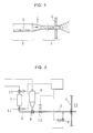
- Fig. 2 and Fig. 3 are explanatory illustrations of catalyst feeding devices
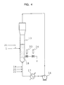
- Fig. 4 is an explanatory illustration of a reaction apparatus of fluidized bed type.
- the present invention provides a process for feeding a catalyst which is characterized in that, in the vapor phase polymerization of olefin using a fluidized bed reactor, the cross-sectional area of a catalyst feeding pipe is reduced in its midway when a powder catalyst is fed intermittently into a high pressure reactor by using a gas.
- the catalysts used in the process of the present invention are highly active olefin polymerization catalysts, which are exemplified by conventionally known ones such as Ziegler catalyst and Philips catalyst.
- the catalysts are powder with average particle sizes in the range of 10 to 200 I.Lm.
- An embodiment of a catalyst feeding pipe used in the present invention is shown in Fig. 1.
- the catalyst feeding pipe 1 comprises a fore pipe 2 of a larger diameter and a rear pipe 3 of a smaller diameter 3.
- the open end portion of the rear pipe 3 is passed through the wall 4 of a reactor and it is led into the inside of the reactor.
- a predetermined quantity of a catalyst 5 is weighed and is fed into the fore pipe 2.
- the inner diameter of the fore pipe 2 is comparatively large because the quantity of dose of the catalyst must be large to some extent as described above.
- the catalyst particles 5 fed into the fore pipe 2 are transferred in the direction of arrows into the rear pipe 3 having a smaller diameter by the flow of an inert gas which is fed from the foremost side.
- the velocity of the catalyst particles is increased and the catalyst particles are continuously passed into the reactor together with the flow of the gas.
- the particles of catalyst 5 move slowly along the lower inside face of the pipe 2 because the velocity of gas flow is low.
- the fore pipe 2 can be slightly inclined.
- the inner diameter of the rear pipe 3 is made small in order to accelerate the flow of gas and improve the dispersion of the catalyst particles 5.
- the inner diameter of the pipe 3 is desirably made small to reduce the rate of gas flow.
- the velocity of gas flow in the rear pipe 3 is determined according to the following factors:
- the value of Ap x v is the driving force of the feed of a catalyst.
- this value is too large, however, too much quantity of the inert gas is introduced into the reactor, which reduces the partial pressure of olefin and lowers the rate of reaction. Accordingly, the value of Ap x v is naturally limited.
- both the values of d and I determines the resistance to gas flow, they have a direct influence to the above Ap.
- the values of the above factors may be set in the following ranges.
- a suitable inner diameter of the foregoing fore pipe 2 is 5-30 mmq) because it receives more than a certain amount of a weighed catalyst and it is preferably 10-25 mm ⁇ .
- the inner diameter of the fore pipe 2 is less than 5 mm ⁇ , the quantity of one feed of a catalyst is too small, which increases the repetition of the feeding of a catalyst, which is accompanied by troublesome operation.
- the inner diameter is more than 30 mm ⁇ , it is not desirable because the continuous flashing of the catalyst particles is difficult even when the inner diameter of the rear pipe 3 is adjusted.
- the gas velocity in the catalyst feeding pipe 1 is in the range of 3-10 m/sec, preferably 4-8 m/sec in the fore pipe 2 and 10-60 m/sec, preferably 15-50 m/sec in the rear pipe 3.
- the state of flow in the transferring of particles with a gas flow is described on page 269 of Bulk Handling Technique of Powdery Particles, edited by Nippon Huntai Kogyo Gijutu Kyokai, published by Nikkan Kogyo Shimbunsha.
- the ratio in cross-sectional areas of the rear pipe 3 to the fore pipe 2 is in the range of 5-50%.
- the ratio of cross-sectional area is less than 5%, the catalyst feeding pipe 1 is liable to be blocked.
- the ratio of cross-sectional area is more than 50%, the catalyst in the state of lumps is fed into the reactor, which is not desirable because polymer blocks are liable to be formed.
- the cross-sectional area of the boundary portion between the fore pipe 2 and the rear pipe 3 of the catalyst feeding pipe 1 is gradually reduced.
- both the members are connected with a reducing joint.
- the reference numeral 6 denotes a catalyst reservoir tank and 7, an inert gas reservoir tank.
- the valve 8 among automatic ball valves in Fig. 2 is opened and the other valves are closed.
- the catalyst measuring valve 9 is opened in the horizontal direction.
- the valve 10 is once opened to fill up the inert gas reservoir tank 7 with an inert gas and the valve is closed then.
- the catalyst measuring valve 9 is then opened in the vertical direction to allow the catalyst to flow down from the catalyst reservoir tank 6 into the fore pipe 2.
- a valve 11 is then opened, the valve 8 is closed and the valve 12 is opened after that.
- the valve 12 is closed, the valve 8 is opened and the valve 11 is closed returning to the initial state.
- Fig. 3 only the valve 8 is opened and all the other valves are closed in the state before the feeding of the catalyst, like the embodiment in Fig. 2.
- the inert gas reservoir tank 7 is filled with an inert gas by opening once and then closing the valve 10.
- the valve 14 is then opened and closed to introduce a portion of the catalyst into the space between the valves 14 and 15.
- the valve 11 is then opened and the valve 8 is closed. After that, by opening the valve 15, the subdivided catalyst is flashed into the reactor 13 through the fore pipe 2 and the rear pipe 3 by the gas flow.
- the valve 15 is closed, the valve 8 is opened and the valve 11 is closed to return to the initial state.
- the diameter of the catalyst measuring valve 9 in Fig. 2 and that of the measuring portion between the valves 14 and 15 in Fig. 3 are made large to some extent so as to allow the catalyst powder to drop. That is, like the fore pipe 2, the inner diameter of them may be 5 to 30 mm ⁇ , preferably 10 to 25 mm ⁇ .
- a fluidized bed reactor 13 shown in Fig. 4 was used. Gas was circulated through a loop comprising a blower 16, a cooler 17 and a flow regulator (not shown). The gas which was introduced into the reactor 13 was evenly distributed by a distribution plate 18.
- the powder of previously dried linear low density polyethylene was fed into a reactor and the temperature in the reactor 13 was maintained at 85°C by circulating a gas with the above blower 16.
- hydrogen was fed through a line 19
- a mixture of 1-butene and ethylene was fed through a line 20.
- Nitrogen gas was fed from a line 21 so as to control the nitrogen concentration at 35 mole % and the total pressure was maintained at 20 kg/cm 2 .G.
- Polymerization reaction was started with feeding a solution of triethylaluminum in hexane as a catalyst promoter through a pipe 22 and a highly active solid catalyst through a catalyst feeding pipe 1.
- Ti, Mg and AI were carried on silica carrier.
- the feeding of the solid catalyst was carried out using a device shown in Fig. 2.
- the inner diameters of the valves 9 and 12 and the fore pipe 2 were 10 mm and the inner diameter of the rear pipe 3 was 4 mm (ratio in cross-sectional areas: 16%).
- a reducing joint of 10 mm in length was used for the diameter-reduced portion from the 10 mmq) end to the 4 mmq) end.
- the continual feed of a powder catalyst in small doses can be done without difficulty by reducing midway the cross section of a catalyst feeding pipe.
- the operation can be continued for a long time by avoiding the formation of lumps of polymer.
Landscapes
- Chemical & Material Sciences (AREA)
- Organic Chemistry (AREA)
- Chemical Kinetics & Catalysis (AREA)
- Health & Medical Sciences (AREA)
- Medicinal Chemistry (AREA)
- Polymers & Plastics (AREA)
- Engineering & Computer Science (AREA)
- Combustion & Propulsion (AREA)
- Polymerisation Methods In General (AREA)
- Addition Polymer Or Copolymer, Post-Treatments, Or Chemical Modifications (AREA)
Abstract
Applications Claiming Priority (3)
| Application Number | Priority Date | Filing Date | Title |
|---|---|---|---|
| JP2192424A JP2857916B2 (ja) | 1990-07-20 | 1990-07-20 | 気相重合流動床の触媒供給方法 |
| JP192424/90 | 1990-07-20 | ||
| PCT/JP1991/000968 WO1992001722A1 (fr) | 1990-07-20 | 1991-07-19 | Procede d'alimentation en catalyseur d'un lit fluidise pour proceder a une polymerisation en phase vapeur |
Publications (3)
| Publication Number | Publication Date |
|---|---|
| EP0596111A4 EP0596111A4 (fr) | 1992-10-21 |
| EP0596111A1 true EP0596111A1 (fr) | 1994-05-11 |
| EP0596111B1 EP0596111B1 (fr) | 1997-10-22 |
Family
ID=16291089
Family Applications (1)
| Application Number | Title | Priority Date | Filing Date |
|---|---|---|---|
| EP91913082A Expired - Lifetime EP0596111B1 (fr) | 1990-07-20 | 1991-07-19 | Procede d'alimentation en catalyseur d'un lit fluidise pour proceder a une polymerisation en phase vapeur |
Country Status (6)
| Country | Link |
|---|---|
| US (2) | US5202396A (fr) |
| EP (1) | EP0596111B1 (fr) |
| JP (1) | JP2857916B2 (fr) |
| CA (1) | CA2066575C (fr) |
| DE (1) | DE69128040T2 (fr) |
| WO (1) | WO1992001722A1 (fr) |
Cited By (3)
| Publication number | Priority date | Publication date | Assignee | Title |
|---|---|---|---|---|
| WO2016151098A1 (fr) | 2015-03-24 | 2016-09-29 | Sabic Global Technologies B.V. | Procédé de transition entre des catalyseurs incompatibles |
| US10494455B2 (en) | 2014-12-22 | 2019-12-03 | Sabic Global Technologies B.V. | Process for transitioning between incompatible catalysts |
| US10577435B2 (en) | 2015-08-26 | 2020-03-03 | Sabic Global Technologies B.V. | Ethylene gas phase polymerisation process |
Families Citing this family (9)
| Publication number | Priority date | Publication date | Assignee | Title |
|---|---|---|---|---|
| US5433924A (en) * | 1994-03-31 | 1995-07-18 | Exxon Chemical Patents Inc. | Method and apparatus for feeding a catalyst |
| US6245868B1 (en) * | 1998-05-29 | 2001-06-12 | Univation Technologies | Catalyst delivery method, a catalyst feeder and their use in a polymerization process |
| JP4087682B2 (ja) * | 2002-11-07 | 2008-05-21 | 株式会社日本触媒 | 吸水性樹脂の製造方法および製造装置 |
| ES2304653T3 (es) * | 2005-07-22 | 2008-10-16 | Kemya Al-Jubail Petrochemical Company | Sistema de control de presion. |
| US8841391B2 (en) | 2008-10-03 | 2014-09-23 | Ineos Sales (Uk) Limited | Process for the introduction of a polymerisation catalyst into a gas-phase fluidised bed |
| EP2172262A1 (fr) * | 2008-10-03 | 2010-04-07 | Ineos Europe Limited | Procédé |
| CN101724109B (zh) * | 2008-10-30 | 2011-10-12 | 中国石油化工股份有限公司 | 一种用于烯烃聚合工艺的催化剂进料管路的装置 |
| CN102271795A (zh) | 2008-12-29 | 2011-12-07 | 巴塞尔聚烯烃意大利有限责任公司 | 用于将催化剂供给到聚合反应器中的方法 |
| JP5459697B2 (ja) * | 2009-02-27 | 2014-04-02 | 住友化学株式会社 | 粉粒体の移送配管、オレフィン重合体の製造装置、粉粒体の移送方法及びオレフィン重合体の製造方法 |
Family Cites Families (5)
| Publication number | Priority date | Publication date | Assignee | Title |
|---|---|---|---|---|
| US3790036A (en) * | 1969-11-21 | 1974-02-05 | Union Carbide Corp | Fluid bed polymerization catalyst injection system |
| US3779712A (en) * | 1971-11-26 | 1973-12-18 | Union Carbide Corp | Particulate solids injector apparatus |
| IN145649B (fr) * | 1974-12-16 | 1985-01-05 | Standard Oil Co | |
| FR2562077B1 (fr) * | 1984-03-30 | 1986-06-27 | Bp Chimie Sa | Dispositif et procede d'introduction d'une poudre a activite catalytique dans un reacteur de polymerisation a lit fluidise |
| JP5245750B2 (ja) | 2008-02-26 | 2013-07-24 | 日本精工株式会社 | レゾルバ装置及びモータ |
-
1990
- 1990-07-20 JP JP2192424A patent/JP2857916B2/ja not_active Expired - Fee Related
-
1991
- 1991-07-19 WO PCT/JP1991/000968 patent/WO1992001722A1/fr not_active Ceased
- 1991-07-19 CA CA002066575A patent/CA2066575C/fr not_active Expired - Fee Related
- 1991-07-19 EP EP91913082A patent/EP0596111B1/fr not_active Expired - Lifetime
- 1991-07-19 US US07/842,094 patent/US5202396A/en not_active Expired - Lifetime
- 1991-07-19 DE DE69128040T patent/DE69128040T2/de not_active Expired - Fee Related
-
1993
- 1993-02-22 US US08/020,758 patent/US5310833A/en not_active Expired - Fee Related
Non-Patent Citations (1)
| Title |
|---|
| See references of WO9201722A1 * |
Cited By (4)
| Publication number | Priority date | Publication date | Assignee | Title |
|---|---|---|---|---|
| US10494455B2 (en) | 2014-12-22 | 2019-12-03 | Sabic Global Technologies B.V. | Process for transitioning between incompatible catalysts |
| WO2016151098A1 (fr) | 2015-03-24 | 2016-09-29 | Sabic Global Technologies B.V. | Procédé de transition entre des catalyseurs incompatibles |
| US10494454B2 (en) | 2015-03-24 | 2019-12-03 | Sabic Global Technologies B.V. | Process for transitioning between incompatible catalysts |
| US10577435B2 (en) | 2015-08-26 | 2020-03-03 | Sabic Global Technologies B.V. | Ethylene gas phase polymerisation process |
Also Published As
| Publication number | Publication date |
|---|---|
| DE69128040D1 (de) | 1997-11-27 |
| EP0596111B1 (fr) | 1997-10-22 |
| DE69128040T2 (de) | 1998-05-20 |
| WO1992001722A1 (fr) | 1992-02-06 |
| EP0596111A4 (fr) | 1992-10-21 |
| CA2066575A1 (fr) | 1992-01-21 |
| US5310833A (en) | 1994-05-10 |
| CA2066575C (fr) | 2002-01-29 |
| JP2857916B2 (ja) | 1999-02-17 |
| US5202396A (en) | 1993-04-13 |
| JPH0480206A (ja) | 1992-03-13 |
Similar Documents
| Publication | Publication Date | Title |
|---|---|---|
| US5928612A (en) | Apparatus and process for polymerising olefin in gas phase | |
| EP0596111A1 (fr) | Procede d'alimentation en catalyseur d'un lit fluidise pour proceder a une polymerisation en phase vapeur | |
| RU2167164C2 (ru) | Способ и устройство для газофазной полимеризации альфа-олефинов | |
| EP0584574B1 (fr) | Procédé de production de polymères collants | |
| MXPA97002102A (en) | Procedure and apparatus for alfa-olefi gaseous phase polymerization | |
| KR101426308B1 (ko) | 올레핀의 중합을 위한 기체 상 방법 및 장치 | |
| EP0549252A1 (fr) | Procédé de polymérisation d'alpha-oléfines en phase gazeuse dans un réacteur à lit fluidisé | |
| EP1246853B1 (fr) | Procede de polimerisation et de copolymerisation en phase gazeuse de monomeres olefiniques | |
| EP0993472B1 (fr) | Processus de polymerisation | |
| AU731412B2 (en) | Polymerisation process | |
| KR0147829B1 (ko) | 중합배지에 활성제 및 활성 억제제를 동시에 첨가하여 조절된 알파-올레핀 기체상 중합공정 | |
| US5470540A (en) | Apparatus and process for introducing a suspension into a reactor | |
| US5385991A (en) | Method for producing polyolefin | |
| RU2075484C1 (ru) | Способ получения (со)полимеров этилена | |
| EP0830892B1 (fr) | Appareil et procédé pour la polymérisation d'oléfine en phase gazeuse | |
| EP1105212B1 (fr) | Procede permettant d'introduire un catalyseur solide dans une cuve fluidisee ou en mouvement | |
| EP2185597B1 (fr) | Alimentation en continu de produits auxiliaires destinés à la polymérisation d'oléfines | |
| EP1080120B1 (fr) | Procede de polymerisation en phase gazeuse | |
| US20060014914A1 (en) | Apparatus for continuous polymerization of olefin, method for transferring a polymer powder, and method for continuous polymerization of olefin | |
| JPH061804A (ja) | ポリオレフィンの製造法 | |
| AU719107C (en) | Process and apparatus for the gas-phase polymerization of alpha-olefins | |
| HK1011373B (en) | Apparatus and process for polymerising olefin in gas phase |
Legal Events
| Date | Code | Title | Description |
|---|---|---|---|
| PUAI | Public reference made under article 153(3) epc to a published international application that has entered the european phase |
Free format text: ORIGINAL CODE: 0009012 |
|
| 17P | Request for examination filed |
Effective date: 19920724 |
|
| AK | Designated contracting states |
Kind code of ref document: A1 Designated state(s): DE FR GB |
|
| 17Q | First examination report despatched |
Effective date: 19940926 |
|
| GRAG | Despatch of communication of intention to grant |
Free format text: ORIGINAL CODE: EPIDOS AGRA |
|
| GRAH | Despatch of communication of intention to grant a patent |
Free format text: ORIGINAL CODE: EPIDOS IGRA |
|
| GRAH | Despatch of communication of intention to grant a patent |
Free format text: ORIGINAL CODE: EPIDOS IGRA |
|
| GRAA | (expected) grant |
Free format text: ORIGINAL CODE: 0009210 |
|
| AK | Designated contracting states |
Kind code of ref document: B1 Designated state(s): DE FR GB |
|
| REF | Corresponds to: |
Ref document number: 69128040 Country of ref document: DE Date of ref document: 19971127 |
|
| ET | Fr: translation filed | ||
| PLBE | No opposition filed within time limit |
Free format text: ORIGINAL CODE: 0009261 |
|
| STAA | Information on the status of an ep patent application or granted ep patent |
Free format text: STATUS: NO OPPOSITION FILED WITHIN TIME LIMIT |
|
| 26N | No opposition filed | ||
| REG | Reference to a national code |
Ref country code: GB Ref legal event code: IF02 |
|
| PGFP | Annual fee paid to national office [announced via postgrant information from national office to epo] |
Ref country code: FR Payment date: 20040528 Year of fee payment: 14 |
|
| PGFP | Annual fee paid to national office [announced via postgrant information from national office to epo] |
Ref country code: GB Payment date: 20040706 Year of fee payment: 14 |
|
| PGFP | Annual fee paid to national office [announced via postgrant information from national office to epo] |
Ref country code: DE Payment date: 20040920 Year of fee payment: 14 |
|
| PG25 | Lapsed in a contracting state [announced via postgrant information from national office to epo] |
Ref country code: GB Free format text: LAPSE BECAUSE OF NON-PAYMENT OF DUE FEES Effective date: 20050719 |
|
| PG25 | Lapsed in a contracting state [announced via postgrant information from national office to epo] |
Ref country code: DE Free format text: LAPSE BECAUSE OF NON-PAYMENT OF DUE FEES Effective date: 20060201 |
|
| GBPC | Gb: european patent ceased through non-payment of renewal fee |
Effective date: 20050719 |
|
| PG25 | Lapsed in a contracting state [announced via postgrant information from national office to epo] |
Ref country code: FR Free format text: LAPSE BECAUSE OF NON-PAYMENT OF DUE FEES Effective date: 20060331 |
|
| REG | Reference to a national code |
Ref country code: FR Ref legal event code: ST Effective date: 20060331 |