EP0596880B1 - Laseraufzeichnungsgerät - Google Patents
Laseraufzeichnungsgerät Download PDFInfo
- Publication number
- EP0596880B1 EP0596880B1 EP91913797A EP91913797A EP0596880B1 EP 0596880 B1 EP0596880 B1 EP 0596880B1 EP 91913797 A EP91913797 A EP 91913797A EP 91913797 A EP91913797 A EP 91913797A EP 0596880 B1 EP0596880 B1 EP 0596880B1
- Authority
- EP
- European Patent Office
- Prior art keywords
- mirror
- laser
- laser beam
- path
- displacement
- Prior art date
- Legal status (The legal status is an assumption and is not a legal conclusion. Google has not performed a legal analysis and makes no representation as to the accuracy of the status listed.)
- Expired - Lifetime
Links
- 238000010330 laser marking Methods 0.000 title claims abstract description 29
- 238000006073 displacement reaction Methods 0.000 claims abstract description 36
- 238000010304 firing Methods 0.000 claims abstract description 8
- 239000011159 matrix material Substances 0.000 claims description 6
- 239000000463 material Substances 0.000 description 3
- 230000003287 optical effect Effects 0.000 description 3
- 239000010410 layer Substances 0.000 description 2
- 229910000639 Spring steel Inorganic materials 0.000 description 1
- 238000005452 bending Methods 0.000 description 1
- 238000007640 computer printing Methods 0.000 description 1
- 238000010276 construction Methods 0.000 description 1
- 238000001514 detection method Methods 0.000 description 1
- 238000002845 discoloration Methods 0.000 description 1
- 230000000694 effects Effects 0.000 description 1
- 238000012423 maintenance Methods 0.000 description 1
- 238000000034 method Methods 0.000 description 1
- 238000007639 printing Methods 0.000 description 1
- 238000009987 spinning Methods 0.000 description 1
- 230000003068 static effect Effects 0.000 description 1
- 239000002344 surface layer Substances 0.000 description 1
- 230000001360 synchronised effect Effects 0.000 description 1
Images


Classifications
-
- B—PERFORMING OPERATIONS; TRANSPORTING
- B41—PRINTING; LINING MACHINES; TYPEWRITERS; STAMPS
- B41J—TYPEWRITERS; SELECTIVE PRINTING MECHANISMS, i.e. MECHANISMS PRINTING OTHERWISE THAN FROM A FORME; CORRECTION OF TYPOGRAPHICAL ERRORS
- B41J2/00—Typewriters or selective printing mechanisms characterised by the printing or marking process for which they are designed
- B41J2/435—Typewriters or selective printing mechanisms characterised by the printing or marking process for which they are designed characterised by selective application of radiation to a printing material or impression-transfer material
- B41J2/47—Typewriters or selective printing mechanisms characterised by the printing or marking process for which they are designed characterised by selective application of radiation to a printing material or impression-transfer material using the combination of scanning and modulation of light
-
- B—PERFORMING OPERATIONS; TRANSPORTING
- B23—MACHINE TOOLS; METAL-WORKING NOT OTHERWISE PROVIDED FOR
- B23K—SOLDERING OR UNSOLDERING; WELDING; CLADDING OR PLATING BY SOLDERING OR WELDING; CUTTING BY APPLYING HEAT LOCALLY, e.g. FLAME CUTTING; WORKING BY LASER BEAM
- B23K26/00—Working by laser beam, e.g. welding, cutting or boring
- B23K26/08—Devices involving relative movement between laser beam and workpiece
- B23K26/082—Scanning systems, i.e. devices involving movement of the laser beam relative to the laser head
Definitions
- This invention relates to lasers and, more particularly, to laser dot-matrix marking and printing, hereinafter referred to as "marking".
- Laser marking is well known in the art and in one such laser marking arrangement a pulsed laser beam is directed through an optical system including a laser beam deflecting means, the beam deflecting means is controlled by a computer and a programme in the computer controls the deflecting means to cause the path of the laser beam to be traversed through a fixed angle, thus to sweep or "scan" a target.
- the laser beam is caused to scan in one plane and the target is displaced in a direction at right angles to the said plane of laser beam displacement whereupon the scan of the laser beam in combination with the target displacement, allows marking over an area of the target.
- the computer further controls the firing of the laser, in pre-programmed positions along the scan path of the laser beam over each or selected scans, whereupon a desired dot-matrix marking over an area of the target is obtained.
- Such an arrangement comprising a computer controlled laser with a laser beam deflecting means arranged to direct the laser beam to scan a target in one plane is, hereinafter referred to as "a laser marking system of the type defined".
- the target area may comprise a laminate, the external layer of which is burnt away or vaporized by the laser beam to expose the second layer which is differently coloured from the surface layer, or the heat generated by the beam may cause a distinctive discoloration of the target surface or the beam may etch the surface of the target.
- Any given target surface to be marked by a laser beam requires a minimum energy density of the beam over a predetermined dwell period to produce a satisfactory marking of the surface.
- the length of the laser pulse required for a given target surface is inversely proportional to the available laser power and proportional to the area of the target surface in the path of the laser beam when the laser is pulsed.
- the United Kingdom Patent Publication No. 2133352 discloses a laser marking system of the type defined wherein the output beam of an RF excited wave guide or non-wave guide C02 laser is directed through an acousto-optic deflector, electronic control means synchronized with the laser drive means drive the acousto-optic deflector so as to selectively deflect the laser pulses in space to produce a one-dimension array of pulses, and an optical system focuses the pulses in said array onto an article to be marked.
- Acousto-optic deflectors are relatively expensive, as also is the optical system provided to receive the output beam from the acousto-optic deflector to focus said beam and to give an acceptable scan dimensions for the focussed beam.
- the acousto-optic deflector is replaced by a mirror arrangement, which may include a multi-faceted spinning mirror or a two mirror system in which one mirror is fixed and the other mirror is displaced by an electronic device, such as a piezoelectric transducer.
- An object of the present invention is to provide a laser beam deflecting means of relatively cheap construction which affords a relatively wide range of scan, which affords a high degree of accuracy for the direction of the beam and which, in practise, offers a relatively fast rate of operation.
- a laser marking arrangement wherein a laser beam deflecting means causes the path of a laser beam to scan in one plane, a target is displaced in a direction at right angles to the said plane of scan and a computer controls the firing of the laser at pre-programmed positions along the said scan path, over each or selected scans, whereupon a desired dot-matrix marking over an area of the target is obtained
- the laser beam path deflecting means includes a mirror arranged in the path of the laser beam, a mirror displacing device is arranged to displace the said mirror between two extreme positions defining a predetermined angle and said predetermined angle defines the angle of scan for the path of the laser beam, characterised in that the said mirror displacing device is arranged to displace the said mirror through said predetermined angle in one direction at a rate of displacement faster than the rate of displacement in the other direction and the laser is controlled to fire only whilst the mirror is being traversed in the direction affording the slower rate of displacement.
- the laser marking arrangement is characterised in that the mirror displacing device is arranged to displace the laser beam path through its predetermined angle of displacement in a series of steps and the laser is controlled to fire only when the path of the laser beam is stable between successive said steps.
- the laser marking arrangement is characterised in that said laser beam deflecting means includes two mirror displacing devices.
- the marking arrangement is characterised in that both said mirror displacing devices act on the mirror to displace the said mirror through its said predetermined angle of displacement.
- each said mirror displacing device is arranged to displace a mirror individual thereto and the path of the laser beam is deflected by both mirrors to step through the full scan angle.
- one of said mirror displacing devices has a smaller displacement than the other of said devices and that displacing device having the smaller displacement makes a plurality of complete displacement cycles for each complete displacement cycle made by the other displacing device.
- the laser marking arrangement is characterised in that the, or each, mirror displacing device includes an electrical device which undergoes a change of shape in response to electrical signals.
- the laser marking arrangement is characterised in that the, or each, said electrical device is of the group including piezo-electric devices, electro-strictive devices and magneto-strictive devices.
- the, or each, mirror displacing means includes a flexure hinge device.
- the laser marking arrangement is characterised by a computer, arranged to drive the mirror displacing means and to control the firing of the laser in accordance with a predetermined programme.
- a computer 11 controls the firing of a pulsing laser 12.
- the beam 13 from the laser 12 passes through a focussing lens 14 to a first mirror 15 and is deflected thereby to a second mirror 16 which directs the beam 13 to a target T to be marked.
- the target T is displacing at uniform speed in a direction at right angles to the scanning plane of the beam 13.
- the computer 11 includes a programme for a desired marking to be applied to the target T.
- a sensing device 17 in the path of the target T detects the leading edge of target T entering the marking zone and initiates the computer printing programme.
- the mirror 15 is mounted on a displacing device 18, the second mirror 16 is mounted on a displacing device 19 and the devices 18 and 19 include electrical devices 20 and 21 respectively which receive operating signals from the computer 11 via lines 22 and 23 respectively.
- the electrical devices 20 and 21 comprise devices which undergo a change of shape in response to electrical signals and may conveniently comprise electro-strictive devices, magneto-strictive devices, or piezo-electric devices.
- the signals given to said devices 20 and 21 on lines 22 and 23 cause dimensional change of said devices 20 and 21 to effect displacement of the mirror displacing devices 18 and 19 respectively.
- a mirror displacing device 18 comprises a so-called flexure hinge device, wherein a block 24 of spring steel has a rectangular opening 25 through its mid-regions and has one end region (the upper end as viewed in Fig. 2) machined to define an inverted prism block 26 supported by two narrow sections 27 and 28 of the block material.
- the section 27 extends to the main body of the block 24 and the section 28 terminates at its lower end in a block 29, which connects to the main body of the block 24 via a narrow section of block material 30 substantially at right angles to the section 28.
- a narrow section of block material 31 extends downwardly from the block 29 and has a shoe 32 formed on its bottom end.
- the electrical device 20 in this example a piezo-electric device, fits snugly between the undersurface of the shoe 32 and the internal surface of the rectangular opening 25 remote from the shoe 32.
- the flat surface 26 a on the prism block 26 is highly polished to comprise the mirror 15.
- the narrow section 27, the narrow section 28, the narrow section 30 and the narrow section 31 all comprise flexure "hinges” and when a signal on the line 22 causes the electrical device 20 to expand, the block 29 is displaced upwardly, against the resistance to bending of the sections 27, 28, 30 and 31 and the upward loading on the block 29 causes the prism block 26 to deflect and change the plane of the mirror surface 26 a .
- the prism block 26 When the prism block 26 has fully deflected and the signal on line 22 is terminated the prism block 26 is rapidly returned to its start position by the energy stored in the sections 27, 28, 30 and 31.
- the resonance frequency of the flexure hinge devices 18 or 19 can be changed by altering the characteristics of the sections 27, 28, 30 and 31 and thus the displacing device 19 is identical to the flexure hinge illustrated in Fig. 2 and described above, with the exception that the sections 27, 28, 30 and 31 are longer to allow the deflection of the mirrored surface 26 a to be greater than that of the device 18.
- the extension of the electrical device 21, on receipt of a signal on the line 23, will also be greater than that of the device 20.
- flexure hinge device illustrated in Fig. 2 and described above is only one simple embodiment intended to illustrate the operation of such a hinge device and, as is well known in the art of flexure hinges, such flexure hinge devices can afford a wide range of deflections and can be readily designed to afford a desired displacement under the action of a selected electrical device.
- the displacing device 18 is arranged to make a number of complete displacement cycles during each complete displacement cycle of the displacement device 19.
- Fig. 3A illustrates the wave form for the displacement of the mirror 15 and, as will be readily seen from the figure, the wave form is a saw-tooth form with the expansion of the device 20 generating the slope and the return, under the action of the sections 27 and 30 of the flexure hinge, almost vertical.
- Fig. 3B illustrates the wave form for the displacement of the mirror 16 and, as will be seen from the figure 3B, the wave form is also a saw tooth form with the expansion of the device 21 generating the slope and the return under the action of the sections 27, 28, 30 and 31 of the flexure hinge device almost vertical.
- Fig. 3C shows, graphically, how the high frequency, low amplitude displacements of the mirror 15 superimposed on the low frequency, high amplitude displacements of the mirror 16 produce a "staircase" wave form for the displacement of the path of the laser beam 13 reflected by the mirror 16 towards the target T and whereby the laser beam path is angularly displaced through a series of small angular displacements, with a dwell period between the adjacent displacements, whilst the device 21 is extending and returns rapidly (in one cycle of the mirror 15) when the signal to the device 21 is terminated.
- the base line ⁇ 0 and the final position ⁇ F before the device 21 returns determine the extreme positions for the laser beam path but, as the laser 12 is arranged to fire only when the path of the laser beam is stationary the laser can fire only at positions ⁇ 1 to ⁇ 7 inclusive and thus the angle ⁇ 1 to ⁇ 7 defines the effective scan angle ⁇ 0 to ⁇ M of the laser beam 13.
- the laser 12 under the control of computer 11, is arranged to fire only whilst the laser beam path is in a dwell period ⁇ 1 to ⁇ 7 inclusive and dwell periods ⁇ 1 to ⁇ 7 inclusive define the total number of spot markings which can be made in each scan of the path of the laser beam 13.
- the length of the laser pulse can be equal to the length of the dwell period and thus a most effective marking of the target T can be obtained.
- Fig. 3C there are seven dwell periods ⁇ 1 to ⁇ 7 inclusive for each complete displacement movement of the mirror 16 and, if the laser beam 13 scans the target T five times, the laser can be controlled to mark a character on a 7 x 5 dot-matrix arrangement.
- the target T may comprise any article to be marked and in practise a plurality of targets T may be displaced successively through the path of the laser beam 13 by a conveying means and said targets T can be marked with identical or different marking, dependant upon the programme or programmes stored in the computer.
- the laser 12 As laser 12 is fired in response to signals from the computer, which contains the desired programme of the marking to be applied to the target T, and as the mirror 16 can perform any desired number of scans for the target area of each target T passing through the path of the beam 13, the laser 12 can be fired to produce any desired dot-matrix pattern the computer can accept.
- the marking arrangement according to the invention can work at very high speeds.
- the laser marking system proposed by the present invention maintains its accuracy over long operating periods with the minimum of maintenance.
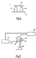
- Fig. 4 shows a second embodiment for displacing the laser beam 13 and wherein two electrical devices 41, 42, which may be of identical form to the devices 20 and 21 respectively, act between a fixed base X and a common mirror 43.
- the computer sends signals to the devices 41 and 42 to cause said devices to expand and contract, the device 41 expanding and contracting with high frequency, low amplitude, whilst the device 42 operates at low frequency high amplitude.
- the surface of the mirror presented to the laser beam 13 displaces in a manner approximating a "staircase" wave form to displace the laser beam path through a succession of small angular displacements with a dwell period between said successive angular displacement movements.
- a laser 51 is arranged to direct its beam 52 onto a mirror 53, supported by a displacing device 54, and the mirror 53 reflects the beam 52 towards a target T displacing in the direction perpendicular to the plane of the scan angle ⁇ S of the laser beam 52.
- a focussing lens 55 is located to focus the beam 52 to the desired spot size at the plane of marking on the target T.
- the displacing device 54 may be similar to the displacing device illustrated in Fig. 2 and will then comprise an electrical device 56 and a flexure hinge device 57.
- the displacing device 54 is driven by a computer 58 which extends a stepping voltage signal, as shown in Fig. 6, to the electrical device 56 and whereupon the electrical device 56 extends in a series of steps to cause the path of the laser beam to sweep through its fixed angle of scan.
- the computer 58 causes the mirror 53 to step the path of the laser beam 52 through its fixed angle of scan and the computer 58 activates the laser 51, in accordance with a predetermined programme for marking, whilst the path of the laser beam 52 is substantially stable between successive steps of the mirror 53, thereby to obtain the pulse length of the beam on each spot on the target necessary to effectively mark the target.
- Fig. 6 shows voltage V plotted against time t for the signals transmitted by the computer to the electrical device 56 in the Fig. 5 embodiment and wherein the stepping voltage defines 7 dwell periods "D" within which the voltage is substantially stable and the laser 51 can be fired.
- the dwell period between successive steps when the laser beam is held substantially stable will be arranged to be of sufficient duration as to allow the laser beam to effectively mark the target.
- the laser beam is stepped through its angle of scan and the laser is fired only during dwell periods of the laser beam and, with the laser beam static when the laser is fired, the marking spots applied to the target are of substantially uniform shape and configuration and a most accurate and clear marking of the target is thereby obtained.
- a computer 61 controls a laser 62 and extends signals to a piezo-electric device 63 driving a flexure hinge device 64.
- the flexure hinge device 64 supports a mirror 65 and the laser beam 66 from the laser 62 passes through a focussing lens 67 to strike the mirror 65 and be deflected thereby onto a target T.
- the computer 61 sends a continuously increasing signal to the piezo-electrical device to cause said device to continuously expand and, on termination of the signal, the piezo-electrical device immediately returns to its start position.
- the mirror 65 is displaced continuously in one direction under the action of the piezo-electric device and, contrary to the previous examples, the computer 61 is arranged to fire the laser 62 whilst the mirror 65 is being displaced in the direction caused by the expansion of the piezo-electric device 63.
- the computer 61 is arranged to fire the laser 62 at a number of preselected signal strengths for the continuously increasing signal to the piezo-electric device 63, and thus at a predetermined number of spaced apart locations along the path of scan, so that successive firings of the laser 62 are spaced apart in the scan direction of the laser beam.
Landscapes
- Optics & Photonics (AREA)
- Physics & Mathematics (AREA)
- Engineering & Computer Science (AREA)
- Plasma & Fusion (AREA)
- Mechanical Engineering (AREA)
- Lasers (AREA)
- Laser Beam Processing (AREA)
- Mechanical Optical Scanning Systems (AREA)
- Glass Compositions (AREA)
- Mechanical Light Control Or Optical Switches (AREA)
- Semiconductor Lasers (AREA)
- Holo Graphy (AREA)
- Laser Beam Printer (AREA)
- Thermal Transfer Or Thermal Recording In General (AREA)
Claims (10)
- Laseraufzeichnungsgerät, bei dem eine Laserstrahl-Ablenkeinrichtung den Weg eines Laserstrahls (13, 52, 66) in einer Ebene abtasten läßt, ein Ziel (T) in einer zu der Abtastebene rechtwinkligen Richtung verschoben wird und ein Computer (11, 58, 61) über jede Abtastung oder über ausgewählte Abtastungen das Auslösen des Lasers (12, 51, 62) in programmierten Stellungen längs des Abtastweges steuert, woraufhin auf einer Fläche des Ziels (T) eine gewünschte Rasteraufzeichnung erhalten wird, wobei die Laserstrahl-Ablenkeinrichtung einen Spiegel (16, 26a, 43, 53, 65) enthält, der auf dem Weg des Laserstrahls (13, 52 oder 66) angeordnet ist, und eine Spiegelverstellvorrichtung (18, 19, 24, 41, 42, 57, 64) dafür eingerichtet ist, den Spiegel (16, 26a, 43, 53, 65) zwischen zwei Endstellungen zu verstellen, die einen vorbestimmten Winkel definieren, der den Abtastwinkel für den Weg des Laserstrahls (13, 52, 66) definiert, dadurch gekennzeichnet, daß die Spiegelverstellvorrichtung (18, 19, 24, 41, 42, 57, 64) dafür eingerichtet ist, den Spiegel (16, 26a, 43, 53, 65) über den vorbestimmten Winkel in der einen Richtung mit einer Verstellgeschwindigkeit zu verstellen, die größer als die Verstellgeschwindigkeit in der anderen Richtung ist, und daß der Laser (12, 51, 62) gesteuert wird, nur auszulösen, während der Spiegel (16, 26a, 43, 53, 65) in der Richtung verfahren wird, die die niedrigere Verstellgeschwindigkeit bietet.
- Laseraufzeichnungsgerät gemäß Anspruch 1, dadurch gekennzeichnet, daß die Spiegelverstellvorrichtung (18, 19, 24, 41, 42, 57, 64) dafür eingerichtet ist, den Weg des Laserstrahls in einer Folge von Schritten über seinen vorbestimmten Verstellwinkel zu verstellen, und daß der Laser (12, 51, 62) gesteuert wird, nur auszulösen, wenn der Weg des Laserstrahls (13, 52, 66) zwischen aufeinanderfolgenden Verstellschritten unveränderlich ist.
- Laseraufzeichnungsgerät gemäß Anspruch 1 oder 2, dadurch gekennzeichnet, daß die Laserstrahl-Ablenkeinrichtung zwei Spiegelverstellvorrichtungen (18, 19, 24, 41, 42) enthält.
- Laseraufzeichnungsgerät gemäß Anspruch 3, dadurch gekennzeichnet, daß beide Spiegelverstellvorrichtungen (41, 42) auf den Spiegel (43) wirken, um den Spiegel (43) über seinen vorbestimmten Verstellwinkel zu verstellen.
- Laseraufzeichnungsgerät gemäß Anspruch 3, dadurch gekennzeichnet, daß jede Spiegelverstellvorrichtung (18, 19) dafür eingerichtet ist, einen individuellen Spiegel (15, 16) zu verstellen, und daß der Weg des Laserstrahls (13) durch beide Spiegel (15, 16) abgelenkt wird, um über den vollen Abtastwinkel zu schreiten.
- Laseraufzeichnungsgerät gemäß Anspruch 3, 4 oder 5, dadurch gekennzeichnet, daß eine der Spiegelverstellvorrichtungen (18, 24, 41) eine kleinere Verstellung als die andere Verstellvorrichtung (19, 24, 42) aufweist und daß die Verstellvorrichtung (18, 24, 41) mit der kleineren Verstellung für jeden von der anderen Verstellvorrichtung (19, 24, 42) durchgeführten vollständigen Verstellzyklus eine Vielzahl von vollständigen Verstellzyklen durchführt.
- Laseraufzeichnungsgerät gemäß einem der vorhergehenden Ansprüche, dadurch gekennzeichnet, daß die oder jede Spiegelverstellvorrichtung (18, 19, 24, 41, 42, 57, 64) eine elektrische Vorrichtung (20, 21, 41, 42, 56, 63) enthält, die als Antwort auf elektrische Signale eine Formänderung erfährt.
- Laseraufzeichnungsgerät gemäß Anspruch 7, dadurch gekennzeichnet, daß die elektrische Vorrichtung (20, 21, 41, 42, 56, 63) zu der Gruppe gehört, die piezoelektrische Vorrichtungen, elektrostriktive Vorrichtungen und magnetostriktive Vorrichtungen umfaßt.
- Laseraufzeichnungsgerät gemäß einem der vorhergehenden Ansprüche, dadurch gekennzeichnet, daß die oder jede Spiegelverstellvorrichtung (18, 19, 24, 57, 64) eine Biegegelenkvorrichtung enthält.
- Laseraufzeichnungsgerät gemäß einem der vorhergehenden Ansprüche, gekennzeichnet durch einen Computer (11, 58, 61), der dafür eingerichtet ist, die Spiegelverstellvorrichtung (18, 19, 24, 41, 42, 57, 64) anzutreiben und das Auslösen des Lasers in Übereinstimmung mit einem vorbestimmten Programm zu steuern.
Applications Claiming Priority (2)
| Application Number | Priority Date | Filing Date | Title |
|---|---|---|---|
| GB909003268A GB9003268D0 (en) | 1990-02-13 | 1990-02-13 | Improvements in or relating to lasers |
| PCT/GB1991/001264 WO1993003456A1 (en) | 1990-02-13 | 1991-07-26 | Oscillating mirrors for laser printer |
Publications (2)
| Publication Number | Publication Date |
|---|---|
| EP0596880A1 EP0596880A1 (de) | 1994-05-18 |
| EP0596880B1 true EP0596880B1 (de) | 1996-12-27 |
Family
ID=37398888
Family Applications (1)
| Application Number | Title | Priority Date | Filing Date |
|---|---|---|---|
| EP91913797A Expired - Lifetime EP0596880B1 (de) | 1990-02-13 | 1991-07-26 | Laseraufzeichnungsgerät |
Country Status (9)
| Country | Link |
|---|---|
| US (1) | US5600478A (de) |
| EP (1) | EP0596880B1 (de) |
| JP (1) | JPH08500059A (de) |
| AT (1) | ATE146887T1 (de) |
| CA (1) | CA2114109C (de) |
| DE (1) | DE69123854T2 (de) |
| ES (1) | ES2097812T3 (de) |
| GB (2) | GB9003268D0 (de) |
| WO (1) | WO1993003456A1 (de) |
Families Citing this family (17)
| Publication number | Priority date | Publication date | Assignee | Title |
|---|---|---|---|---|
| IT1242638B (it) * | 1990-11-15 | 1994-05-16 | Hal 9000 Informatica Srl | Deflettore alternativo di luce laser |
| DE29514319U1 (de) * | 1995-09-07 | 1997-01-16 | Sator, Alexander Paul, 20249 Hamburg | Vorrichtung zum Beschriften von Gegenständen |
| US5915063A (en) * | 1997-01-15 | 1999-06-22 | Colbourne; Paul | Variable optical attenuator |
| US5864417A (en) * | 1997-06-25 | 1999-01-26 | Ho; Ko-Liang | Laser audio-visual equipment |
| US6706995B2 (en) * | 1998-07-16 | 2004-03-16 | Ball Corporation | Laser light marking of a container portion |
| US20030024913A1 (en) * | 2002-04-15 | 2003-02-06 | Downes Joseph P. | Laser scanning method and system for marking articles such as printed circuit boards, integrated circuits and the like |
| US6528762B2 (en) * | 2001-02-12 | 2003-03-04 | W. A. Whitney Co. | Laser beam position control apparatus for a CNC laser equipped machine tool |
| US7119351B2 (en) * | 2002-05-17 | 2006-10-10 | Gsi Group Corporation | Method and system for machine vision-based feature detection and mark verification in a workpiece or wafer marking system |
| AU2003240315B2 (en) * | 2002-06-28 | 2009-07-16 | Cv Laser Pty Ltd | Scanning device and method of scanning an optical beam over a surface |
| AUPS326102A0 (en) | 2002-06-28 | 2002-07-18 | Clvr Pty Ltd | Scanning device and method of scanning an optical beam over a surface |
| US6839127B1 (en) | 2003-09-15 | 2005-01-04 | Deere & Company | Optical range finder having a micro-mirror array |
| US7064810B2 (en) * | 2003-09-15 | 2006-06-20 | Deere & Company | Optical range finder with directed attention |
| US7916898B2 (en) * | 2003-09-15 | 2011-03-29 | Deere & Company | Method and system for identifying an edge of a crop |
| US7705268B2 (en) * | 2004-11-11 | 2010-04-27 | Gsi Group Corporation | Method and system for laser soft marking |
| US20060189091A1 (en) * | 2004-11-11 | 2006-08-24 | Bo Gu | Method and system for laser hard marking |
| RU2457522C1 (ru) * | 2011-03-02 | 2012-07-27 | Государственное Научное Учреждение "Институт Физики Имени Б.И. Степанова Национальной Академии Наук Беларуси" | Установка лазерной маркировки |
| US10286488B2 (en) * | 2015-03-06 | 2019-05-14 | Intel Corporation | Acousto-optics deflector and mirror for laser beam steering |
Family Cites Families (13)
| Publication number | Priority date | Publication date | Assignee | Title |
|---|---|---|---|---|
| GB1520281A (en) * | 1974-07-10 | 1978-08-02 | Canon Kk | Electrophotographic recording apparatus |
| JPS5574511A (en) * | 1978-11-30 | 1980-06-05 | Toshiba Corp | Driving system of optical scanning device |
| JPS55111917A (en) * | 1979-02-22 | 1980-08-29 | Toshiba Corp | Reciprocating photo scanner |
| US4388652A (en) * | 1979-04-30 | 1983-06-14 | Harris Corporation | Synchronized, variable speed capstan motor drive system for facsimile recorder |
| DE3035315C2 (de) * | 1980-09-18 | 1984-07-12 | Erwin Sick Gmbh Optik-Elektronik, 7808 Waldkirch | Piezoelektrische Lichtablenkvorrichtung |
| GB2133352B (en) * | 1983-01-13 | 1985-09-11 | Laser Applic Limited | A laser marking system |
| US4497465A (en) * | 1983-03-31 | 1985-02-05 | Storage Technology Partners Ii | Pivotal mechanism upon which tracking mirrors and the like used in optical systems may be mounted |
| JPS61117517A (ja) * | 1984-11-13 | 1986-06-04 | Fuji Photo Film Co Ltd | ガルバノメ−タの走査速度の補正方法 |
| GB2175705B (en) * | 1985-05-24 | 1989-04-19 | Stc Plc | Dirigible reflector and mounting made of crystal material |
| US4648683A (en) * | 1985-05-28 | 1987-03-10 | Hewlett-Packard Company | Adjustable length slotless female contact for connectors |
| US4714310A (en) * | 1986-04-21 | 1987-12-22 | Sri International | Method and apparatus for dynamic focusing control of a radiant energy beam |
| JPS6314117A (ja) * | 1986-07-04 | 1988-01-21 | Konica Corp | レ−ザ記録装置 |
| US4971413A (en) * | 1987-05-13 | 1990-11-20 | Nikon Corporation | Laser beam depicting apparatus |
-
1990
- 1990-02-13 GB GB909003268A patent/GB9003268D0/en active Pending
-
1991
- 1991-02-12 GB GB9102868A patent/GB2241592B/en not_active Expired - Fee Related
- 1991-07-26 DE DE69123854T patent/DE69123854T2/de not_active Expired - Fee Related
- 1991-07-26 WO PCT/GB1991/001264 patent/WO1993003456A1/en not_active Ceased
- 1991-07-26 JP JP3513007A patent/JPH08500059A/ja active Pending
- 1991-07-26 EP EP91913797A patent/EP0596880B1/de not_active Expired - Lifetime
- 1991-07-26 CA CA002114109A patent/CA2114109C/en not_active Expired - Fee Related
- 1991-07-26 AT AT91913797T patent/ATE146887T1/de active
- 1991-07-26 US US08/185,854 patent/US5600478A/en not_active Expired - Fee Related
- 1991-07-26 ES ES91913797T patent/ES2097812T3/es not_active Expired - Lifetime
Also Published As
| Publication number | Publication date |
|---|---|
| ES2097812T3 (es) | 1997-04-16 |
| GB9102868D0 (en) | 1991-03-27 |
| DE69123854T2 (de) | 1997-07-31 |
| CA2114109A1 (en) | 1993-02-18 |
| JPH08500059A (ja) | 1996-01-09 |
| WO1993003456A1 (en) | 1993-02-18 |
| EP0596880A1 (de) | 1994-05-18 |
| GB2241592A (en) | 1991-09-04 |
| DE69123854D1 (de) | 1997-02-06 |
| ATE146887T1 (de) | 1997-01-15 |
| GB2241592B (en) | 1994-10-05 |
| US5600478A (en) | 1997-02-04 |
| GB9003268D0 (en) | 1990-04-11 |
| CA2114109C (en) | 2002-05-28 |
Similar Documents
| Publication | Publication Date | Title |
|---|---|---|
| EP0596880B1 (de) | Laseraufzeichnungsgerät | |
| US5229573A (en) | Print quality laser marker apparatus | |
| EP0385911B1 (de) | Laserbohrer | |
| US6653593B2 (en) | Control system for ablating high-density array of vias or indentation in surface of object | |
| JP5654234B2 (ja) | X−y高速穴あけシステム | |
| US5229574A (en) | Print quality laser marker apparatus | |
| US8680430B2 (en) | Controlling dynamic and thermal loads on laser beam positioning system to achieve high-throughput laser processing of workpiece features | |
| KR100691924B1 (ko) | 재료 가공 장치 및 방법 | |
| GB2199158A (en) | Light beam switching system for optical fibres | |
| CA2168662A1 (en) | Laser marker system | |
| JP2003136270A (ja) | レーザ加工装置 | |
| GB2133352A (en) | A laser marking system | |
| EP1246712A1 (de) | Vorrichtung und verfahren zum zielen | |
| EP1392467A4 (de) | Verfahren und vorrichtung zur verbesserung von laserlochauflösung | |
| JP3365388B2 (ja) | レーザ加工光学装置 | |
| JPH0732183A (ja) | Co2レーザ加工装置 | |
| EP0420198A2 (de) | Strahlabtastvorrichtung und Bildinformationsschreibvorrichtung | |
| EP0976002A1 (de) | Verschiebsystem fur einen laserstrahl, zum beispiel lasermakierungssystem | |
| JP3619493B2 (ja) | レーザ加工のパルス安定化方法 | |
| EP0810913B1 (de) | Laserverarbeitungsverfahren | |
| JP3027654B2 (ja) | 鋼板へのレーザマーキング方法 | |
| JP2726326B2 (ja) | アークセンサ及び溶接線の探索方法 | |
| JPH0480708A (ja) | 光線走査装置 | |
| JPH02299786A (ja) | レーザマーキング開始時のドット間隔制御方法 | |
| WO2001027665A1 (en) | Method control system and apparatus for ablating high-density array of vias or indentation in surface of object |
Legal Events
| Date | Code | Title | Description |
|---|---|---|---|
| PUAI | Public reference made under article 153(3) epc to a published international application that has entered the european phase |
Free format text: ORIGINAL CODE: 0009012 |
|
| 17P | Request for examination filed |
Effective date: 19940111 |
|
| AK | Designated contracting states |
Kind code of ref document: A1 Designated state(s): AT BE CH DE DK ES FR GB GR IT LI NL SE |
|
| GRAG | Despatch of communication of intention to grant |
Free format text: ORIGINAL CODE: EPIDOS AGRA |
|
| 17Q | First examination report despatched |
Effective date: 19960304 |
|
| GRAH | Despatch of communication of intention to grant a patent |
Free format text: ORIGINAL CODE: EPIDOS IGRA |
|
| RAP1 | Party data changed (applicant data changed or rights of an application transferred) |
Owner name: IMAJE S.A. |
|
| GRAH | Despatch of communication of intention to grant a patent |
Free format text: ORIGINAL CODE: EPIDOS IGRA |
|
| GRAA | (expected) grant |
Free format text: ORIGINAL CODE: 0009210 |
|
| AK | Designated contracting states |
Kind code of ref document: B1 Designated state(s): AT BE CH DE DK ES FR GB GR IT LI NL SE |
|
| PG25 | Lapsed in a contracting state [announced via postgrant information from national office to epo] |
Ref country code: LI Effective date: 19961227 Ref country code: GR Free format text: LAPSE BECAUSE OF FAILURE TO SUBMIT A TRANSLATION OF THE DESCRIPTION OR TO PAY THE FEE WITHIN THE PRESCRIBED TIME-LIMIT Effective date: 19961227 Ref country code: DK Effective date: 19961227 Ref country code: CH Effective date: 19961227 Ref country code: BE Effective date: 19961227 Ref country code: AT Effective date: 19961227 |
|
| REF | Corresponds to: |
Ref document number: 146887 Country of ref document: AT Date of ref document: 19970115 Kind code of ref document: T |
|
| REF | Corresponds to: |
Ref document number: 69123854 Country of ref document: DE Date of ref document: 19970206 |
|
| ITF | It: translation for a ep patent filed | ||
| ET | Fr: translation filed | ||
| PG25 | Lapsed in a contracting state [announced via postgrant information from national office to epo] |
Ref country code: SE Effective date: 19970327 |
|
| REG | Reference to a national code |
Ref country code: ES Ref legal event code: FG2A Ref document number: 2097812 Country of ref document: ES Kind code of ref document: T3 |
|
| REG | Reference to a national code |
Ref country code: CH Ref legal event code: PL |
|
| PG25 | Lapsed in a contracting state [announced via postgrant information from national office to epo] |
Ref country code: GB Free format text: LAPSE BECAUSE OF NON-PAYMENT OF DUE FEES Effective date: 19970726 |
|
| PLBE | No opposition filed within time limit |
Free format text: ORIGINAL CODE: 0009261 |
|
| STAA | Information on the status of an ep patent application or granted ep patent |
Free format text: STATUS: NO OPPOSITION FILED WITHIN TIME LIMIT |
|
| 26N | No opposition filed | ||
| GBPC | Gb: european patent ceased through non-payment of renewal fee |
Effective date: 19970726 |
|
| PGFP | Annual fee paid to national office [announced via postgrant information from national office to epo] |
Ref country code: ES Payment date: 20010702 Year of fee payment: 11 |
|
| PGFP | Annual fee paid to national office [announced via postgrant information from national office to epo] |
Ref country code: DE Payment date: 20010725 Year of fee payment: 11 |
|
| PGFP | Annual fee paid to national office [announced via postgrant information from national office to epo] |
Ref country code: FR Payment date: 20010727 Year of fee payment: 11 |
|
| PGFP | Annual fee paid to national office [announced via postgrant information from national office to epo] |
Ref country code: NL Payment date: 20010730 Year of fee payment: 11 |
|
| PG25 | Lapsed in a contracting state [announced via postgrant information from national office to epo] |
Ref country code: ES Free format text: LAPSE BECAUSE OF NON-PAYMENT OF DUE FEES Effective date: 20020727 |
|
| PG25 | Lapsed in a contracting state [announced via postgrant information from national office to epo] |
Ref country code: NL Free format text: LAPSE BECAUSE OF NON-PAYMENT OF DUE FEES Effective date: 20030201 Ref country code: DE Free format text: LAPSE BECAUSE OF NON-PAYMENT OF DUE FEES Effective date: 20030201 |
|
| PG25 | Lapsed in a contracting state [announced via postgrant information from national office to epo] |
Ref country code: FR Free format text: LAPSE BECAUSE OF NON-PAYMENT OF DUE FEES Effective date: 20030331 |
|
| NLV4 | Nl: lapsed or anulled due to non-payment of the annual fee |
Effective date: 20030201 |
|
| REG | Reference to a national code |
Ref country code: FR Ref legal event code: ST |
|
| REG | Reference to a national code |
Ref country code: ES Ref legal event code: FD2A Effective date: 20030811 |
|
| PG25 | Lapsed in a contracting state [announced via postgrant information from national office to epo] |
Ref country code: IT Free format text: LAPSE BECAUSE OF NON-PAYMENT OF DUE FEES;WARNING: LAPSES OF ITALIAN PATENTS WITH EFFECTIVE DATE BEFORE 2007 MAY HAVE OCCURRED AT ANY TIME BEFORE 2007. THE CORRECT EFFECTIVE DATE MAY BE DIFFERENT FROM THE ONE RECORDED. Effective date: 20050726 |