EP0597824B1 - Rollenpapierschneidevorrichtung - Google Patents
Rollenpapierschneidevorrichtung Download PDFInfo
- Publication number
- EP0597824B1 EP0597824B1 EP19940101777 EP94101777A EP0597824B1 EP 0597824 B1 EP0597824 B1 EP 0597824B1 EP 19940101777 EP19940101777 EP 19940101777 EP 94101777 A EP94101777 A EP 94101777A EP 0597824 B1 EP0597824 B1 EP 0597824B1
- Authority
- EP
- European Patent Office
- Prior art keywords
- roll paper
- transport
- paper
- cutting device
- transport roller
- Prior art date
- Legal status (The legal status is an assumption and is not a legal conclusion. Google has not performed a legal analysis and makes no representation as to the accuracy of the status listed.)
- Expired - Lifetime
Links
- 238000005520 cutting process Methods 0.000 title claims description 101
- 238000001514 detection method Methods 0.000 claims description 17
- 230000008859 change Effects 0.000 claims description 8
- 230000032258 transport Effects 0.000 description 74
- 230000008901 benefit Effects 0.000 description 8
- 230000000452 restraining effect Effects 0.000 description 8
- 238000010276 construction Methods 0.000 description 7
- 238000003780 insertion Methods 0.000 description 7
- 230000037431 insertion Effects 0.000 description 7
- 238000010586 diagram Methods 0.000 description 6
- 230000004048 modification Effects 0.000 description 6
- 238000012986 modification Methods 0.000 description 6
- 238000011144 upstream manufacturing Methods 0.000 description 6
- 238000004891 communication Methods 0.000 description 4
- 230000007246 mechanism Effects 0.000 description 4
- 230000000994 depressogenic effect Effects 0.000 description 3
- 238000000034 method Methods 0.000 description 3
- 238000003825 pressing Methods 0.000 description 3
- 230000001276 controlling effect Effects 0.000 description 2
- 230000000694 effects Effects 0.000 description 2
- 238000000926 separation method Methods 0.000 description 2
- 238000012546 transfer Methods 0.000 description 2
- 101100096719 Arabidopsis thaliana SSL2 gene Proteins 0.000 description 1
- 101100366560 Panax ginseng SS10 gene Proteins 0.000 description 1
- 230000005856 abnormality Effects 0.000 description 1
- 230000002411 adverse Effects 0.000 description 1
- 230000015572 biosynthetic process Effects 0.000 description 1
- 230000000903 blocking effect Effects 0.000 description 1
- 230000003467 diminishing effect Effects 0.000 description 1
- 238000012840 feeding operation Methods 0.000 description 1
- 230000005484 gravity Effects 0.000 description 1
- WABPQHHGFIMREM-UHFFFAOYSA-N lead(0) Chemical compound [Pb] WABPQHHGFIMREM-UHFFFAOYSA-N 0.000 description 1
- 229920006267 polyester film Polymers 0.000 description 1
- 230000009467 reduction Effects 0.000 description 1
- 230000001105 regulatory effect Effects 0.000 description 1
- 230000004044 response Effects 0.000 description 1
Images






Classifications
-
- G—PHYSICS
- G03—PHOTOGRAPHY; CINEMATOGRAPHY; ANALOGOUS TECHNIQUES USING WAVES OTHER THAN OPTICAL WAVES; ELECTROGRAPHY; HOLOGRAPHY
- G03G—ELECTROGRAPHY; ELECTROPHOTOGRAPHY; MAGNETOGRAPHY
- G03G15/00—Apparatus for electrographic processes using a charge pattern
- G03G15/65—Apparatus which relate to the handling of copy material
- G03G15/6517—Apparatus for continuous web copy material of plain paper, e.g. supply rolls; Roll holders therefor
- G03G15/6523—Cutting
-
- B—PERFORMING OPERATIONS; TRANSPORTING
- B65—CONVEYING; PACKING; STORING; HANDLING THIN OR FILAMENTARY MATERIAL
- B65H—HANDLING THIN OR FILAMENTARY MATERIAL, e.g. SHEETS, WEBS, CABLES
- B65H16/00—Unwinding, paying-out webs
- B65H16/10—Arrangements for effecting positive rotation of web roll
- B65H16/106—Arrangements for effecting positive rotation of web roll in which power is applied to web roll
-
- G—PHYSICS
- G03—PHOTOGRAPHY; CINEMATOGRAPHY; ANALOGOUS TECHNIQUES USING WAVES OTHER THAN OPTICAL WAVES; ELECTROGRAPHY; HOLOGRAPHY
- G03G—ELECTROGRAPHY; ELECTROPHOTOGRAPHY; MAGNETOGRAPHY
- G03G15/00—Apparatus for electrographic processes using a charge pattern
- G03G15/65—Apparatus which relate to the handling of copy material
- G03G15/6517—Apparatus for continuous web copy material of plain paper, e.g. supply rolls; Roll holders therefor
-
- B—PERFORMING OPERATIONS; TRANSPORTING
- B65—CONVEYING; PACKING; STORING; HANDLING THIN OR FILAMENTARY MATERIAL
- B65H—HANDLING THIN OR FILAMENTARY MATERIAL, e.g. SHEETS, WEBS, CABLES
- B65H2301/00—Handling processes for sheets or webs
- B65H2301/10—Selective handling processes
- B65H2301/12—Selective handling processes of sheets or web
- B65H2301/121—Selective handling processes of sheets or web for sheet handling processes, i.e. wherein the web is cut into sheets
-
- B—PERFORMING OPERATIONS; TRANSPORTING
- B65—CONVEYING; PACKING; STORING; HANDLING THIN OR FILAMENTARY MATERIAL
- B65H—HANDLING THIN OR FILAMENTARY MATERIAL, e.g. SHEETS, WEBS, CABLES
- B65H2301/00—Handling processes for sheets or webs
- B65H2301/40—Type of handling process
- B65H2301/41—Winding, unwinding
- B65H2301/415—Unwinding
- B65H2301/4152—Finishing unwinding process
- B65H2301/41524—Detecting trailing edge
-
- G—PHYSICS
- G03—PHOTOGRAPHY; CINEMATOGRAPHY; ANALOGOUS TECHNIQUES USING WAVES OTHER THAN OPTICAL WAVES; ELECTROGRAPHY; HOLOGRAPHY
- G03G—ELECTROGRAPHY; ELECTROPHOTOGRAPHY; MAGNETOGRAPHY
- G03G2215/00—Apparatus for electrophotographic processes
- G03G2215/00362—Apparatus for electrophotographic processes relating to the copy medium handling
- G03G2215/00443—Copy medium
- G03G2215/00451—Paper
- G03G2215/00455—Continuous web, i.e. roll
-
- Y—GENERAL TAGGING OF NEW TECHNOLOGICAL DEVELOPMENTS; GENERAL TAGGING OF CROSS-SECTIONAL TECHNOLOGIES SPANNING OVER SEVERAL SECTIONS OF THE IPC; TECHNICAL SUBJECTS COVERED BY FORMER USPC CROSS-REFERENCE ART COLLECTIONS [XRACs] AND DIGESTS
- Y10—TECHNICAL SUBJECTS COVERED BY FORMER USPC
- Y10S—TECHNICAL SUBJECTS COVERED BY FORMER USPC CROSS-REFERENCE ART COLLECTIONS [XRACs] AND DIGESTS
- Y10S83/00—Cutting
- Y10S83/929—Particular nature of work or product
- Y10S83/949—Continuous or wound supply
-
- Y—GENERAL TAGGING OF NEW TECHNOLOGICAL DEVELOPMENTS; GENERAL TAGGING OF CROSS-SECTIONAL TECHNOLOGIES SPANNING OVER SEVERAL SECTIONS OF THE IPC; TECHNICAL SUBJECTS COVERED BY FORMER USPC CROSS-REFERENCE ART COLLECTIONS [XRACs] AND DIGESTS
- Y10—TECHNICAL SUBJECTS COVERED BY FORMER USPC
- Y10T—TECHNICAL SUBJECTS COVERED BY FORMER US CLASSIFICATION
- Y10T83/00—Cutting
- Y10T83/444—Tool engages work during dwell of intermittent workfeed
- Y10T83/4458—Work-sensing means to control work-moving or work-stopping means
- Y10T83/446—With means to initiate tool feed by same control impulse
-
- Y—GENERAL TAGGING OF NEW TECHNOLOGICAL DEVELOPMENTS; GENERAL TAGGING OF CROSS-SECTIONAL TECHNOLOGIES SPANNING OVER SEVERAL SECTIONS OF THE IPC; TECHNICAL SUBJECTS COVERED BY FORMER USPC CROSS-REFERENCE ART COLLECTIONS [XRACs] AND DIGESTS
- Y10—TECHNICAL SUBJECTS COVERED BY FORMER USPC
- Y10T—TECHNICAL SUBJECTS COVERED BY FORMER US CLASSIFICATION
- Y10T83/00—Cutting
- Y10T83/525—Operation controlled by detector means responsive to work
- Y10T83/54—Actuation of tool controlled by work-driven means to measure work length
-
- Y—GENERAL TAGGING OF NEW TECHNOLOGICAL DEVELOPMENTS; GENERAL TAGGING OF CROSS-SECTIONAL TECHNOLOGIES SPANNING OVER SEVERAL SECTIONS OF THE IPC; TECHNICAL SUBJECTS COVERED BY FORMER USPC CROSS-REFERENCE ART COLLECTIONS [XRACs] AND DIGESTS
- Y10—TECHNICAL SUBJECTS COVERED BY FORMER USPC
- Y10T—TECHNICAL SUBJECTS COVERED BY FORMER US CLASSIFICATION
- Y10T83/00—Cutting
- Y10T83/525—Operation controlled by detector means responsive to work
- Y10T83/541—Actuation of tool controlled in response to work-sensing means
-
- Y—GENERAL TAGGING OF NEW TECHNOLOGICAL DEVELOPMENTS; GENERAL TAGGING OF CROSS-SECTIONAL TECHNOLOGIES SPANNING OVER SEVERAL SECTIONS OF THE IPC; TECHNICAL SUBJECTS COVERED BY FORMER USPC CROSS-REFERENCE ART COLLECTIONS [XRACs] AND DIGESTS
- Y10—TECHNICAL SUBJECTS COVERED BY FORMER USPC
- Y10T—TECHNICAL SUBJECTS COVERED BY FORMER US CLASSIFICATION
- Y10T83/00—Cutting
- Y10T83/889—Tool with either work holder or means to hold work supply
- Y10T83/896—Rotatable wound package supply
Definitions
- the present invention relates to roll paper cutting devices for use with, for example, copying machines or like image forming apparatus for forming copy images, for example, on paper precut to a specified size.
- image forming apparatus such as copying machines
- image forming apparatus As the means for feeding copy paper to the image forming position, image forming apparatus, such as copying machines, generally have incorporated therein a cassette for containing paper precut to a specified size and delivering the cut paper therefrom one sheet after another.
- sheets of such cut paper are manually inserted one by one into a copy paper inlet formed in the body of the apparatus.
- the apparatus for use with such cut paper has the drawback of necessitating a large space for holding the paper therein when the paper to be used has a large size. Accordingly, paper in the form of a roll is usually set in a specific roll paper cutting device, cut to the desired size by the device and then fed to the image forming apparatus through a paper inlet.
- JP 58009162 a separate sheet paper feed device is provided but such devices can create other problems.
- the image forming apparatus is adapted to be equipped with the roll paper cutting device as an optional device, with signal communication effected to associate the device with the apparatus, the modification of the apparatus and wiring require much labour to impair the optionality.
- the roll paper cutting device is to be used as such an optional device, the roll paper feed means within the device and the paper feed means within the apparatus must be adapted to transport paper at the same speed, whereas this encounters extreme difficulty. If there is a difference between the two feed means in transport speed, the roll paper is likely to become deflected or tensioned to produce an adverse effect on the formation of images especially when elongated documents are copied. Further when the two speeds are to be made identical, the drive source for the roll paper feed means, for example, must be finely adjusted, but the means for effecting the fine adjustment is expensive, consequently diminishing the advantage of the image forming apparatus.
- the present invention provides a roll paper cutting device attachable to an image forming apparatus main body and containing cutting means for cutting roll paper contained in said roll paper cutting device and means for feeding the paper to transport means of the image forming apparatus, the device comprising at least one transport roller for transporting the roll paper, drive means for driving said at least one transport roller, drive change means for selectively putting the transport roller in an idly rotatable state or in a driven state, control means for controlling said drive change means to put the transport roller in said driven state to transport the leading edge of the paper to the transport means of the image forming apparatus main body and to put the transport roller in said idly rotatable state to permit it to be rotated by the paper when said main body transport means is operable to transport the paper, detecting means for detecting the travel of paper when the transport roller is in said idly rotatable state, said control means and said drive change means being arranged to put said transport roller in said driven state with predetermined timing based on said detection of the paper travel by said detecting means while the transport
- Such an arrangement can be employed to operate the cutting device in the following manner.
- the transport roller is first drivingly rotated the roll paper in the cutting device is transported to a paper feed portion within the image forming apparatus main body.
- all transport rollers are allowed to rotate idly in the standby state for paper feeding, and the image forming apparatus is initiated into a paper feed operation in this state, whereupon the roll paper is pulled out, and the travel of the paper detected.
- This causes the control means to start to drive the transport rollers with suitable timing, whereby the roll paper is automatically fed to the image forming apparatus. Accordingly, even if there is no communication between the cutting device and the apparatus main body, the feed of the roll paper can be started with suitable timing.
- the cutting device can be attached to the apparatus main body by a simple procedure for suitably feeding roll paper to the apparatus main body almost without necessitating modification of the apparatus body, wiring or the like.
- the roll paper cutting device may further comprise means for detecting the amount of transport of the roll paper, said control means controlling the drive change means being arranged to place the transport roller in said idly rotatable state to permit the transport means of the image forming apparatus to transport the paper when a predetermined length of the paper has been extended from the roll cutting device to reach the transport means of the apparatus.
- the roll paper can be first transported from the roll paper cutting device to the transport means within the image forming apparatus main body by the feed means of the device, whereupon the paper is further transported alternatively by the transport means only.
- This makes it possible to transport the paper without problems from deflection and tension, further obviating the need to finely adjust the drive source for the roll paper cutting device and assuring easier control. Consequently, the roll paper can be transported reliably at a low cost.
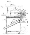
- Fig. 1 shows the overall construction of a copying machine (image forming apparatus) comprising a main body 10 and a roll paper cutting device 12.
- the main body 10 comprises a copying assembly 14, and a copy paper stocking frame 16 having the copying assembly 14 supported thereon.
- roll paper is herein used not in a narrow sense of the term but includes, for example, roll film for use in preparing second original drawings.
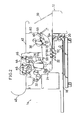
- Fig. 2 shows the interior construction of the copying assembly 14, which has in its lower portion a large paper cassette (sheet container) 18 withdrawably.
- the cassette 18 contains copy paper, which is transported to a photosensitive drum 26 at a higher level via pairs of feed rollers 20,22 and a pair of register rollers 24.
- a copy paper inlet 28 is positioned above the cassette 18. Copy paper is also inserted into the inlet 28 and fed to the copying assembly 14 via the pair of feed rollers 22.
- a fixing unit 38 and a pair of discharge rollers 40 are disposed downstream from the drum 26 with respect to the direction of transport of the copy paper, i.e., toward the front side.
- the exposure unit 44 includes a plurality of rollers 46 for transporting documents, an exposure lamp 48, a lens array 50, etc., whereby an image of the document to be transported is projected onto the drum 26.
- Jam sensor switches 56 to 59 are arranged at two positions upstream from the pair of transport rollers 20 with respect to the paper transport direction, at a position downstream from the drum 26 and at the position of the pair of discharge rollers 40, respectively. These switches 56 to 59 detect the copy paper passing the respective positions. If each of the switches 56 to 59 fails to detect the copy paper upon lapse of a predetermined period of time after the feed of the copy paper, this is interpreted as indicating occurrence of a jam.
- the document feed path 42, transfer-separation unit 34, fixing unit 38, discharge roller pair 40, etc. are accommodated in a common unit housing 60 as a single unitary assembly, which can be withdrawn toward the front in the event of a jam.
- the copy paper stocking frame 16 is internally provided with a copy paper stocking tray (stocking portion) 61 slanting upward toward the front side as seen in FIG. 1.
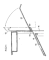
- the inlet side portion of the tray i.e., the front side portion thereof, is provided with a copy paper guide plate (guide member) 62 and a support plate 65 as shown also in FIG. 11.
- the support plate 65 is secured to the inlet portion of the stocking tray 61, extends along the tray 61 and is provided at its front end with a restraining portion 651 projecting upward.
- the guide plate 62 is connected at its base end to the support plate 65 at an inside portion thereof close to the restraining portion 651 (at the left side portion in FIG. 11). Consequently, the paper guide plate 62 is forwardly unfoldable away from the front wall of the stocking frame 16, and is pivotally movable between a guide position (solid-line position in FIG.
- a copy paper holder 63 of polyester film or the like is provided above the stocking tray 61.
- the roll paper cutting device 12 is attached to the front side wall of the stocking frame 16 and is movable upward and downward.
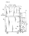
- the mount structure and drive system for the device 12 will be described with reference to FIGS. 3 to 6.
- a pair of guide rails 64 open inward are secured to the opposite sides of the front wall of the copy paper stocking frame 16.
- the guide rails 64 extend from the lower end of the stocking frame 16 to the lower end of the unit housing 60 of the copying assembly 14.
- the roll paper cutting device 12 is movable upward and downward (see the solid-line and phantom-line positions of the device 12 in FIG. 1).
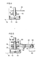
- the cutting device 12 rotatably carries shafts 68, 69 extending through opposite inner side plates 66 (FIGS. 4 to 6) thereof. Rollers 71, 72 loosely fitted in the guide rails 64 are fixed to opposite ends of these shafts 68, 69.
- sprockets 74, 75 are secured to the respective shafts 68, 69.
- identical chains 76 are looped around the sprockets 74, 75 as seen in FIGS. 3 and 6. The upper and lower ends of these chains 76 are secured to the upper and lower ends of the respective guide rails 64.
- a gear 78 is fixed to one end (closer to the plane of FIG. 3) of the shaft 72 and is in mesh with an idle gear 80 which is rotatably supported by the inner side plate 66.
- a drive motor 82 fixed by an unillustrated bracket to the outer side of the inner side plate 66 has a drive shaft 83 which fixedly carries a gear 84 meshing with the idle gear 80.
- the shaft 69 fixedly carries a pulse plate 86 as seen in FIG. 5.
- the device 12 further has means 88 for detecting the amount of rotation (amount of shift) comprising a photosensor including a light-emitting member and a photodetector which are positioned on opposite sides of a slit 87 formed in the pulse plate 86.
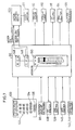
- the cutting device 12 further has incorporated therein a control system (control means) 90 comprising a microcomputer as seen in FIG. 7.
- the rotation amount detector 88 feeds a detection signal to the control system 90.
- the roll paper cutting device 12 further has at its upper portion a copy paper discharge tray 99 (see FIG. 1) which is open obliquely upward. With the device 12 in its upper limit position (solid-line position in FIG. 1), the copy paper delivered from the pair of discharge rollers 40 is accumulated on the discharge tray 99.
- the roll paper cutting device 12 is internally provided with a roll shaft 93 for roll paper 92 upwardly and downwardly movably along a slot 94 formed in each side wall of the device.
- the device also has at its lower portion a pair of rotatable transport rollers 95, 96.
- the roll shaft 93 is biased downward by an unillustrated spring, whereby the roll paper 92 is pressed downward at all times in its entirety, with the periphery thereof held in contact with the transport rollers 95, 96 regardless of the diameter of the roll.
- the transport roller 95 is coupled by unillustrated gears to the driven side of a first clutch 98 which is shown also in FIG. 7.
- a cover 100 is openably attached to the front side (right side in FIG. 8) of the device. When opened (to the phantom-line position of FIG. 8), the cover 100 permits the user to manually set the roll paper 92 in position.
- a holding roller 102 Arranged above the roll paper 92 along a direction upward therefrom are a holding roller 102 (shown only in FIG. 1), a pair of feed rollers 103, 104, a pair of cutters 105, 106 and a pair of discharge rollers 108, 109.
- An outlet 110 for the roll paper 92 is provided above the discharge rollers.
- One of the feed rollers 103, 104 i.e., the feed roller 103 is coupled by gears 111, 112 to the driven side of a second clutch 114 which is shown also in FIG. 7.
- the other feed roller 104 is rotatably attached to a pivotal bracket 118 by a plate spring 116 and is usually held in pressing contact with the feed roller 103 by being biased with the plate spring 116. With the cover 100 in its opened state, the roller 104 can be moved out of contact with the roller 103 by pivotally moving the bracket 118 in the direction of arrow B in FIG. 8.
- the cutter 105 is in the form of a circle partly cut away along a straight line and is connected to a cutter solenoid 120 shown in FIG. 7.
- the cutter 105 is rotated by the energization of the solenoid 120.
- the other cutter 106 is positioned as opposed to the cutter 105 with a paid-off portion of the roll paper 92 interposed therebetween.
- an edge at the intersection of a plane thereof with a cylindrical surface providing the outer periphery of the cutter 105 comes into frictional contct with an edge of the other cutter 106, whereby the roll paper 92 is cut.
- the pair of discharge rollers 108, 109 are in pressing contact with each other.
- the discharge roller 108 at one side is coupled to the feed roller 103 by a train of unillustrated gears and is driven with the feed roller 103.
- the cutting device 12 has a main motor 122 incorporated therein and serving as a drive source for the foregoing rollers.
- the main motor 122 is connected to a motor control board 123 (FIG. 7).
- a drive roller 124 is fixed to the drive shaft of the main motor 122.
- a single belt 126 is reeved around the drive roller 124 and the drive-side portions of the first clutch 98 and the second clutch 114.
- the transport roller 95 in an idly rotatable state is brought into a driven state, and the torque of the drive roller 124 is delivered to the feed roller 103.
- the second clutch 114 is engaged, the feed roller 103 in an idly rotatable state is brought into a driven state, and the torque of the drive roller 124 is transmitted to the feed roller 103.
- the gear ratios concerned are so determined that the feed roller 103 is driven at twice the speed of rotation of the transport roller 95.
- tension rollers for the belt 126 are tension rollers for the belt 126.
- the control panel 130 has ten number entry keys 132, a stop/clear key 134 and a start key 136 as illustrated, and is further provided with a key for selecting a paper feed mode (cassette feed mode or manual insertion mode), a size specifying key for entering the size of sheets to be cut off from the roll paper, a shift start key for starting the shift of the cutting device 12, etc.
- a paper feed mode cassette feed mode or manual insertion mode
- a size specifying key for entering the size of sheets to be cut off from the roll paper
- a shift start key for starting the shift of the cutting device 12, etc.
- the device has inside thereof a first switch 138 so positioned as to contact the cover 100 when the cover 100 is closed, and second and third switches 139 and 140 arranged upstream from the cutters 105, 106 and downstream from the discharge rollers 108, 109, respectively.
- the switches 139, 140 are turned on and off by the roll paper 92 when the paper passes the position of the switch.
- Pulse plates 97, 142 are secured to the respective shafts fixedly carrying the transport roller 95 and the feed roller 103.
- Rotation detectors 143, 144 (FIG. 7), each comprising a light-emitting element and a photodetector, are positioned in corresponding relation with slits in the respective pulse plates 97, 142. These rotation detectors 143, 144 and the switches 138 to 140 feed detection signals to the control system 90.
- the control system 90 comprises a CPU 146, ROM 148 and RAM 150 and carries out the following control operations mainly.
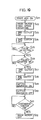
- FIG. 9 shows the operation for feeding the roll paper 92
- FIG. 10 shows a preparatory operation before the start of the feed operation (i.e., step S1 of FIG. 9).
- the copying machine main body 10 is set in the manual insertion mode, in which copy paper is fed from the copy paper inlet 28.
- the roll paper cutting device 12 is allowed to stand as it is if the device is in its upper limit position where the outlet 110 of the device 12 is in register with the inlet 28. If the device 12 is in its lower limit position, the shift start key on the operation panel 130 is depressed, whereby the device 12 is driven upward in its entirety by the drive motor 82, allowing the rotation amount detector 88 to produce a pulse signal.
- the motor 82 is deenergized, whereby the device 12 is automatically brought to a halt at the upper limit position, i.e., at the feed position.
- the guide plate 62 which is unfolded outward under gravity, is in the guide position where the lower surface of the guide plate 62 is in bearing contact with the restraining portion 651 of the support plate 65 as seen in FIG. 11. Accordingly, the copy paper discharged from the copying assembly 14 falls onto the guide plate 62 and is guided by the plate 62 to a specified position on the stocking tray 61.
- the guide plate 62 When the cutting device 12 moves upward from the standby position to the feed position, the guide plate 62 is pushed up from below by the device 12 and automtically folded from the guide position (phantom-line position in FIG. 1) to the retracted position indicated in solid line in FIG. 1.
- some of the number entry keys 132 on the operation panel 130 of the device 12 are manipulated to input data as to the roll paper cutting size and roll paper transport speed to the control system 90.
- the data as to the transport speed is the same as the data representing the copy paper transport speed of the copying machine main body 10.
- step SS1 the cover 100 of the cutting device 12 is opened, and the pivotal bracket 118 is moved in the direction of arrow B in FIG. 8 to move the feed roller 104 out of pressing contact with the feed roller 103, and the leading end of the roll paper 92 wound around the roll shaft 93 is manually inserted through a space between the feed rollers 103, 104 (step SS1).
- the leading end is brought to the position of the second switch 139, turning on the switch 139 (YES for step SS2), whereupon the display lamp 152 of the device 12 goes on (step SS3).
- the operator then discontinues the roll paper setting procedure, and returns the pivotal bracket 118 to bring the roller 104 into contact with the roller 103.
- step SS4 The cover 100 is thereafter closed (step SS4), whereby the first switch 138 is turned on (YES in step SS5), feeding a detection signal to the control system 90, whereupon the system 92 feeds a control signal to the motor control board 123 to rotate the main motor 122 in the forward direction and drive the drive roller 124 clockwise in FIG. 8 (step SS6).
- step SS6 The second clutch 114 is further engaged (step SS7). Consequently, the feed roller 103 and the discharge roller 108 are driven counterclockwise in FIG. 8, pulling out the roll paper 92 in the feed direction.
- the main motor 122 is driven at a transport speed lower than the speed input by the number entry keys 132.
- the roll paper 92 thereafter passes between the discharge rollers 108, 109 and reaches the third switch 140 to turn on the switch 140 (YES in step SS8), whereupon the resulting detection signal is fed to the control system 90, which in turn disengages the second clutch 114 (step SS9). This discontinues the transport of the roll paper 92.
- control system 90 reversely rotates the main motor 122 to drive the drive roller 124 in a direction opposite to the above (step SS10), and further engages the first clutch 98 (step SS11), whereby the transport roller 95 is rotated clockwise in FIG. 8 to draw back the roll paper 92 downward.
- the pulse plate 97 rotating with the transport roller 95 and the rotation detector 143 feed to the control sytem 90 data as to the rotation of the transport roller 95 as a pulse signal.
- the control system 90 disengages the first clutch 98 (step SS13) and deenergizes the main motor 122 (step SS14).
- the pulse number M0 is so determined as to correspond to the distance of the position of cutting by the cutters 105, 106 from the detection position of the third switch 140, so that the operation of steps SS10 to SS14 stops the leading end of the roll paper 92 accurately at the position where the paper is to be cut by the cutters 105, 106.
- Some of the number entry keys 132 are thereafter manipulated on the control panel 130 to enter a pulse number M corresponding to the desired size to which the roll paper is to be cut (step SS15), whereby the preparation for feeding is completed.
- step S3 the start key 136 on the control panel 130 shown in FIG. 7 is depressed (step S2), causing the control system 90 to feed a motor on-off signal and motor clock signal to the motor control board 123 to forwardly drive the main motor 122 at a high speed (step S3).
- the term "high speed” as used herein corresponds to the roll paper transport speed entered by the number entry keys 132, and the motor clock signal corresponding to this speed is fed to the control board 123. If the first clutch 98 is engaged, the above signals cause the transport roller 95 to rotate at a speed equal to the copy paper transport speed of the copying assembly, or if the second clutch 114 is engaged, the feed roller 103 is rotated at twice the speed of the transport roller 95.
- control system 90 first engages the second clutch 114 (step S4), whereby the feed roller 103 is driven counterclockwise in FIG. 8, delivering the roll paper 92 from the outlet 110 into the inlet 28 of the copying assembly 14.
- the rotation of the feed roller 103 is detected by the pulse plate 142 and the rotation detector 144.
- the pulse number of the detection signal reaching a predetermined pulse number M1 (YES in step S5)
- the second clutch 114 is disengaged (step S6) to discontinue the transport of the roll paper 92.
- the pulse number M1 corresponds to the distance of the pair of feed rollers 22 from the cutting position of the cutters 105, 106, so that the operation of steps S4 to S6 brings the leading end of the paper 92 to the position of the pair of feed rollers 22 of the copying assembly 14.
- step S7 engages the first clutch 98 (step S7), thereby driving the transport roller 95.
- the rotation is detected by the rotation detector 143.
- the first clutch 98 is disengaged (step S9) to stop the rotation of the roller 95.
- the operation of steps S7 to S9 rotates the transport roller 95 only, warping the paper at its portion upstream from the feed rollers 103, 104.
- the rollers are now in an idly rotatable state, ready for the start of feed of paper for the machine main body 10.
- the feed rollers 22 in the machine body 10 thereafter operate, starting to feed the roll paper 92, whereby the portion of the roll paper 92 within the device 12 is pulled upward and rotates the feed roller 103 by contact therewith.
- step S10 When this rotation is detected by the rotation detector 144 (YES in step S10), the control system 90 engages the first clutch 98 (step S11) to rotate the transport roller 95.
- the first clutch 98 Upon the pulse number of the detection signal 144 from the detector 144 reaching a predetermined pulse number M3 (YES in step S12), the first clutch 98 is disengaged (step S13).
- the pulse number M3 is the pulse number corresponding to the size of sheet to be cut off from the roll paper 92 and set on the operation panel 130, minus a number of pulses, m, that is, M - m. Accordingly, the operation of steps S11 to S13 transports the roll paper 92 within the device 12 a distance corresponding to the pulse number M3, i.e., M - m, at a speed equal to the feed speed in the machine body 10.
- the control system 90 engages the second clutch 114 (step S14), rotating the feed roller 103, and disengages the second clutch 114 (step S16) upon the pulse number of the detection signal from the rotation detector 144 reaching a predetermined pulse number M4 (YES in step S15).
- control system 90 energizes the cutter solenoid 120 only for a predetermined period of time (step S17) to rotate the cutter 105 one turn and cut the roll paper 92.
- the rear end of the cut sheet of the roll paper 92 thereafter moves past the third switch 140 and turns off the switch 140 (YES in step S18), whereupon the system deenergizes the main motor 122 (step S19) to complete the feed operation.
- paper may be fed manually to the machine main body 10 through the copy paper inlet 28 without using the cutting device 12.
- the shift start key on the operation panel of the device 12 is manipulated to lower the device 12 to its lower limit position, whereby the inlet 28 is exposed at the front side of the machine body 10 and made ready for use. Paper can then be manually inserted into the inlet 28.
- the roll paper cutting device 12 is attached to the copying machine main body 10 so as to be vertically movable between the upper limit position in which the outlet 110 of the device 12 is in register with the copy paper inlet 28 and the lower limit position in which the outlet 110 is away from the inlet 28.
- the roll paper 92 can be fed by the device 12 as positioned in the upper limit position to the machine main body 10 which is an existing copying machine. With the device 12 shifted from the upper limit position to the lower limit position, paper can be fed in the conventional manner utilizing the manual insertion feed mechanism usually incorporated in the main body 10 of the image forming apparatus.
- the copy paper guide plate 62 is shiftable between the guide position and the retracted position with the vertical movement of the cutting device 12, such that even if the guide plate 62 is located at the feed position for the cutting device 12, the device 12 can be driven vertically free of trouble.
- the roll paper cutting device 12 of the present embodiment has the following advantages.
- the paper leading end can be positioned in place by the following modifications.
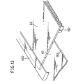
- document rear end detecting means 270 as shown in FIGS. 16 and 17 is connected by a lead wire 266 as shown in FIG. 15 to the same control system 90 as in the foregoing embodiments movably relative to the body of the roll paper cutting device 12.
- the restraining member 268 comprises a mount plate 268a shaped in conformity with the outer plate 10a of the copying machine main body 10, and a side restraining plate 268b extending upright from the mount plate 268a, and is provided at each of opposite sides (near side and remote side in FIG. 17) of the document feed path 42 (see FIG. 2).
- the mount plate 268a is attached to the machine body 10 with a pin 269 as shown in FIG. 17 slidably widthwise of documents.
- the rear end detecting means 270 connected to the cutting device 12 has a mount bracket 272 and a document guide plate 274.
- the mount bracket (mount) 272 is fixed to the restraining member 268 by the pin 269.
- the mount bracket 272 and the document guide plate 274 define therebetween a path (indicated by arrows in FIG. 17) 273 for documents to travel therealong.
- a light-emitting element 276 and a photodetector 277 are arranged at opposite sides of the path 273 to provide a photosensor serving as a rear end detector switch 278.
- the mount bracket 272 and the document guide plate 274 have holes 272a, 274a, respectively, as positioned in corresponding relation with the element 276 and the photodetector 277, such that the switch 278 is turned on or off by the presence or absence of the document blocking the light path.
- the sum of the path length l1 from the position of detection by the rear end detector switch 278 to the position of exposure by the exposure unit 44 and the circumferential length l2 from the position where an image of the document is projected by the exposure unit 44 on the photosensitive drum 26 to the transfer position is made equal to the path length L1 from the cutting position of the cutters 105, 106 of the cutting device 12 to the transfer position, by selecting the position of the rear end detecting means 270.
- control operation to be actually conducted by the control system 90 and the paper feed operation of the embodiment to be performed under the control.
- step S11 in the flow chart is the same as the corresponding operation in the flow charts of FIG. 9.
- the first clutch 98 is engaged (step S11) to operate the transport roller 95, and the rear end of the document being transported by the exposure unit 44 moves past the position of detection by the rear end detector switch 278, whereupon the switch 278, which is on, is turned off to apply the resulting signal to the control system 90.
- the control system 90 disengages the first clutch 98 (step S13) and engages the second clutch 114 (step S14) to drive the feed roller 103.
- step S15 Upon the pulse number of the detection signal from the rotation detector 144 reaching a predetermined pulse number M3 (YES in step S15), the system disengages the second clutch 114 (step S16).
- the roll paper 92 within the cutting device 12 is transported by a length corresponding to the pulse number M3 at twice the feed speed in the machine main body 10. Consequently, the roll paper 92 is transported excessively by a distance corresponding to one-half of the pulse number M3, forming a warped portion upstream from the cutters 105, 106 so as to be cut with proper timing.
- the roll paper cutting device 12 has connected thereto the rear end detecting means 270 for detecting the rear end of the document being transported in the machine main body 10, and the rear end detecting means 270 is positioned suitably in accordance with the internal structure of the main body 10, for the cutters 105, 106 to cut the roll paper with timing based on the time when the rear end is detected. Accordingly, the roll paper can be cut to a size for feeding in conformity with the document size at all times without the need for signal communication between the device and the machine main body. This obviates the need to modify an existing copying machine when the cutting device is to be used for the machine as the machine main body 10.
- the present embodiment also has the advantage that when the position of the rear end detecting means is suitably selected, the cutting device can be used for copying machines which differ variously in interior construction.
- the cutting device 12 may be provided with the drive motor 82 for driving the device 12 itself, and the roll paper feed timing may be determined based on the rotation of the feed roller 103.
- the cutting device 12 can then be given enhanced optionality for use with the machine main body 10.
- the roll paper 92 is warped to provide proper cutting timing, so that the sheet cut off from the roll paper 92 is longer than the document by an amount corresponding to the pulse number M3. If it is desired to make the sheet identical with the document in size, the rear end detecting means 270 may be positioned away from the exposure position a larger distance than in the above case by an amount corresponding to the pulse number M3.
- the cutting operation is started simultaneously with the detection of the rear end according to the present embodiment, the cutting operation may be initiated, for example, a predetermined period of time after the detection of the rear end.
- the user manipulates some of the number entry keys 132 to enter the roll paper transport speed and store the speed in the memory, whereas the serviceman may write the data in conformity with the machine main body.
- a further mode of operation will be described with reference to the flow chart of Fig. 19.
- the device 12 With the cutting device 12 of the first embodiment set in the roll paper feed mode, the device 12 is initially driven to deliver the roll paper 92, and after the leading end of the roll paper 92 has reached the pair of feed rollers 22 within the copying machine main body 10, the paper is transported to the image forming assembly including the drum 26, etc. only by the transport means within the main body 10.
- the control system 90 of the cutting device 12 is so adapted as to effect the above mode of control.
- step S21 the start key 136 on the control panel 130 is depressed (step S21), causing the main motor 122 within the device 12 to rotate at a high speed in the specified direction (step S22).
- step S22 the second clutch 144 is engaged (step S23) to drive the feed roller 103, forwarding the leading end of the roll paper 92 toward the copy paper inlet 28 of the main body 10 via the outlet 110.
- step S24 Upon the pulse count of the pulse signal produced from the rotation detector 14 reaching a predetermined pulse number, the second clutch 114 is disengaged (step S24). At this time, the leading end of the roll paper 92 has been transported to the position of the pair of feed rollers 22 of the main body 10.
- the pair of feed rollers 22 within the main body 10 thereafter starts to feed the paper, upwardly pulling the roll paper portion within the cutting device 12 and rotating the feed rollers 103, 104 which are in contact with the paper 92.
- the rotation is detected by the rotation detector 144 (YES in step S25).
- the second clutch 114 is engaged again (step S27), rotating the feed roller 103 to transport the roll paper 92.
- the second clutch 114 is disengated upon the pulse count of the rotation detecting signal from the rotation detector 144 reaching a specified pulse number (step S28).
- the roll paper portion upstream from the cutters 105, 106 is warped so that the roll paper 92 is to be cut with proper timing.
- the cutter solenoid 120 is then energized (step S29), whereby the cutter 105 is rotated one turn to cut the roll paper 92.
- the solenoid is then deenergized (step S30).
- the rear end of the cut sheet of roll paper 92 thereafter moves past the third switch (discharge switch) 140 to turn off the switch 140 (YES in step S31), whereupon the main motor 122 is deenergized (step S32), whereby the paper feed operation is completed.
- the roll paper 92 is transported only by the feed operation of the copying machine main body 10 after the operation has been started. This obviates the likelihood of the roll paper 92 warping or being tensioned during transport.
Landscapes
- Physics & Mathematics (AREA)
- General Physics & Mathematics (AREA)
- Paper Feeding For Electrophotography (AREA)
- Advancing Webs (AREA)
Claims (7)
- Rollenpapierschneidgerät, das am Hauptkörper (10) einer Bilderzeugungsvorrichtung befestigbar ist und Schneidmittel (105, 106) zum Schneiden von im Rollenpapierschneidgerät enthaltenen Rollenpapier sowie ein Mittel zum Zuführen des Papiers zu Beförderungsmitteln der Bilderzeugungsvorrichtung umfaßt, wobei das Gerät zumindest eine Beförderungswalze (103) zur Beförderung des Rollenpapiers und ein Antriebsmittel (122) zum Antreiben der zumindest einen Beförderungswalze (103) enthält, dadurch gekennzeichnet, daß das Gerät mit folgendem ausgestattet ist: einem Antriebsänderungsmittel (98), um die Beförderungswalze (103) selektiv in einen Leerdrehzustand oder einen angetriebenen Zustand zu versetzen, einem Steuerungsmittel (90) zur Steuerung des Antriebsänderungsmittels (98), um die Beförderungswalze (103) in den angetriebenen Zustand zu versetzen, sodaß die Vorderkante des Papiers zum Beförderungsmittel des Hauptkörpers (10) der Bilderzeugungsvorrichtung transportiert wird, und um die Beförderungswalze (103) in den Leerdrehzustand zu versetzen, um es ihr zu ermöglichen, durch das Papier gedreht zu werden, wenn das Beförderungsmittel des Hauptkörpers das Papier befördert, einem Detektiermittel (144) zum Erkennen der Papierfortbewegung, wenn sich die Beförderungswalze im Leerdrehzustand befindet, wobei das Steuerungsmittel (90) und das Antriebsänderungsmittel (98) angeordnet sind, die Beförderungswalze (103) in einem vorbestimmten Zeitablauf basierend auf dem Erkennen der Papierfortbewegung durch das Detektiermittel (144) in den angetriebenen Zustand zu versetzen, während sich die Beförderungswalze (103) im Leerdrehzustand befindet.
- Rollenpapierschneidgerät nach Anspruch 1, worin das Fortbewegungsdetektiermittel ein Drehdetektor (143) zum Erkennen der Drehung der Beförderungswalze (95) ist.
- Rollenpapierschneidgerät nach Anspruch 1 oder 2, worin das Steuerungsmittel (90) antreibend alle Beförderungswalzen dreht, wenn die Fortbewegung des Rollenpapiers detektiert wird.
- Rollenpapierschneidgerät nach einem der Ansprüche 1 bis 3, umfassend ein Mittel zum Eingeben der Beförderungsgeschwindigkeit des durch die Beförderungswalze (95) transportierten Rollenpapiers, wobei das Steuerungsmittel (90) ausgebildet ist, die Beförderungswalze auf der Basis der eingegebenen Beförderungsgeschwindigkeit anzutreiben.
- Rollenpapierschneidgerät nach einem der vorhergehenden Ansprüche, weiters umfassend ein Mittel (144) zum Detekieren der Beförderungsmenge des Rollenpapiers, wobei das das Antriebsänderungsmittel (98) steuernde Steuerungsmittel (90) angeordnet ist, die Beförderungswalze (103) in den Leerdrehzustand zu versetzen, um es dem Beförderungsmittel der Bilderzeugungsvorrichtung zu ermöglichen, das Papier zu befördern, wenn eine vorbestimmte Länge des Papiers aus dem Rollenschneidgerät ausgefahren wurde, um das Beförderungsmittel der Vorrichtung zu erreichen.
- Rollenpapierschneidgerät nach Anspruch 5, worin das Steuerungsmittel (90) ausgebildet ist, den Schneidzeitablauf so zu steuern, daß das Rollenpapier während seiner Beförderung zu einer Bilderzeugungsanordnung im Hauptkörper der Vorrichtung zu einer vorbestimmten Größe geschnitten wird.
- Bilderzeugungsvorrichtung, die mit einem Rollenpapierschneidgerät nach einem der vorhergehenden Ansprüche ausgestattet ist.
Applications Claiming Priority (11)
| Application Number | Priority Date | Filing Date | Title |
|---|---|---|---|
| JP303717/89 | 1989-11-22 | ||
| JP1303717A JPH0811384B2 (ja) | 1989-11-22 | 1989-11-22 | ロール紙裁断装置 |
| JP308341/89 | 1989-11-27 | ||
| JP1308341A JPH03172279A (ja) | 1989-11-27 | 1989-11-27 | 画像形成装置 |
| JP30833889 | 1989-11-27 | ||
| JP308338/89 | 1989-11-27 | ||
| JP14486/90 | 1990-01-23 | ||
| JP2014486A JP2524415B2 (ja) | 1989-11-27 | 1990-01-23 | 画像形成装置 |
| JP70805/90 | 1990-03-19 | ||
| JP2070805A JPH07115784B2 (ja) | 1990-03-19 | 1990-03-19 | ロール紙供給装置 |
| EP19900312688 EP0429303B1 (de) | 1989-11-22 | 1990-11-21 | Bilderzeugungsgerät und Papierrollenschneidevorrichtung dafür |
Related Parent Applications (1)
| Application Number | Title | Priority Date | Filing Date |
|---|---|---|---|
| EP90312688.6 Division | 1990-11-21 |
Publications (2)
| Publication Number | Publication Date |
|---|---|
| EP0597824A1 EP0597824A1 (de) | 1994-05-18 |
| EP0597824B1 true EP0597824B1 (de) | 1997-03-05 |
Family
ID=27519611
Family Applications (3)
| Application Number | Title | Priority Date | Filing Date |
|---|---|---|---|
| EP19940101777 Expired - Lifetime EP0597824B1 (de) | 1989-11-22 | 1990-11-21 | Rollenpapierschneidevorrichtung |
| EP19900312688 Expired - Lifetime EP0429303B1 (de) | 1989-11-22 | 1990-11-21 | Bilderzeugungsgerät und Papierrollenschneidevorrichtung dafür |
| EP19940101776 Expired - Lifetime EP0597823B1 (de) | 1989-11-22 | 1990-11-21 | Bilderzeugungsgerät und Rollenpapierschneidevorrichtung dafür |
Family Applications After (2)
| Application Number | Title | Priority Date | Filing Date |
|---|---|---|---|
| EP19900312688 Expired - Lifetime EP0429303B1 (de) | 1989-11-22 | 1990-11-21 | Bilderzeugungsgerät und Papierrollenschneidevorrichtung dafür |
| EP19940101776 Expired - Lifetime EP0597823B1 (de) | 1989-11-22 | 1990-11-21 | Bilderzeugungsgerät und Rollenpapierschneidevorrichtung dafür |
Country Status (3)
| Country | Link |
|---|---|
| US (2) | US5216471A (de) |
| EP (3) | EP0597824B1 (de) |
| DE (3) | DE69030120T2 (de) |
Families Citing this family (21)
| Publication number | Priority date | Publication date | Assignee | Title |
|---|---|---|---|---|
| US5144386A (en) * | 1990-03-19 | 1992-09-01 | Mita Industrial Co., Ltd. | Image-forming apparatus having a manual paper supply port located above a paper discharging port |
| US5244163A (en) * | 1990-03-19 | 1993-09-14 | Mita Industrial Co., Ltd. | Construction of supporting shaft of roll of paper |
| JPH085563B2 (ja) * | 1990-11-30 | 1996-01-24 | 三田工業株式会社 | 給紙装置 |
| EP0488661B1 (de) * | 1990-11-30 | 1996-03-06 | Mita Industrial Co. Ltd. | Papierförderer und Bilderzeugungsgerät hierfür |
| JPH06113068A (ja) * | 1992-09-28 | 1994-04-22 | Canon Inc | 記録装置 |
| US5396313A (en) * | 1994-03-23 | 1995-03-07 | Xerox Corporation | Out of media detection system for a roll media feed apparatus |
| US5629754A (en) * | 1994-12-26 | 1997-05-13 | Konica Corporation | Photographic printing apparatus and a roll magazine holder therefor |
| JP3320266B2 (ja) * | 1995-07-31 | 2002-09-03 | 京セラミタ株式会社 | 複写機 |
| US5829898A (en) * | 1995-08-29 | 1998-11-03 | Dynetics Engineering Corporation | Printing assembly with discrete load enhancement apparatus and method |
| US6145423A (en) * | 1995-09-15 | 2000-11-14 | Moore Business Forms, Inc. | Semi-automatic dispenser for linerless labels |
| JPH1035964A (ja) * | 1996-07-22 | 1998-02-10 | Brother Ind Ltd | 用紙移送機構、これを備えた画像記録装置、および画像読取記録装置 |
| US5768675A (en) * | 1996-08-16 | 1998-06-16 | Intermec Corporation | On-demand narrow web electrophotographic printer |
| US6243157B1 (en) * | 1997-08-19 | 2001-06-05 | Fuji Photo Film Co., Ltd. | Photographic printer and photographic printer exposure method |
| US6055704A (en) * | 1998-06-29 | 2000-05-02 | Xerox Corporation | Caster with built-in adjustment |
| US6134747A (en) * | 1999-02-10 | 2000-10-24 | Xerox Corporation | Ball caster with snap-in ball |
| JP4340396B2 (ja) * | 2000-04-21 | 2009-10-07 | 株式会社リコー | 給紙装置および画像形成装置 |
| EP1394091A1 (de) * | 2002-08-30 | 2004-03-03 | Hunkeler AG | Verfahren und Vorrichtung zur Speisung eines Druckers mit Einzelblättern |
| EP2030895A1 (de) * | 2007-08-31 | 2009-03-04 | Uhlmann VisioTec GmbH | Vorrichtung zur überwachten Tablettenabfüllung |
| CA2666239A1 (en) * | 2009-05-20 | 2010-11-20 | The Imaging Systems Group Inc. | Hybrid printer-feeder mechanism |
| US20110292437A1 (en) | 2010-05-28 | 2011-12-01 | Tombs Thomas N | Method for printing a set of images |
| US20110293349A1 (en) | 2010-05-28 | 2011-12-01 | Tombs Thomas N | Printer with variable length receiver supply |
Family Cites Families (16)
| Publication number | Priority date | Publication date | Assignee | Title |
|---|---|---|---|---|
| US3178978A (en) * | 1961-02-27 | 1965-04-20 | Miunesota Mining And Mfg Compa | Tape dispenser |
| US3614572A (en) * | 1970-03-16 | 1971-10-19 | Gen Electric | Automatic control system for crop shear |
| US3820777A (en) * | 1972-07-11 | 1974-06-28 | Xerox Corp | Elevator assembly positioning control |
| US3933082A (en) * | 1972-08-16 | 1976-01-20 | Hans Molly | Axial piston type machine |
| US3922082A (en) * | 1973-10-19 | 1975-11-25 | Cavalier Products Inc | Bond paper photocopying machine |
| US4360263A (en) * | 1979-04-10 | 1982-11-23 | Mita Industrial Company Limited | Copying apparatus |
| US4297930A (en) * | 1979-09-04 | 1981-11-03 | Cx Corporation | Strip cutter having rotatable cutting blade and strip deflecting means |
| US4265153A (en) * | 1980-02-04 | 1981-05-05 | Minnesota Mining And Manufacturing Company | Copy machine with automatic roll supplied copy paper feeding and cutting apparatus and control circuitry |
| JPS589162A (ja) * | 1981-07-09 | 1983-01-19 | Ricoh Co Ltd | シ−ト自動給紙装置 |
| US4660820A (en) * | 1984-09-12 | 1987-04-28 | Xerox Corporation | Paper feeding apparatus for a copying machine/printer |
| JPS6179515A (ja) * | 1984-09-25 | 1986-04-23 | Mitsubishi Heavy Ind Ltd | 板体の定寸切断装置 |
| JPH0661968B2 (ja) * | 1985-08-10 | 1994-08-17 | 株式会社リコー | 記録装置 |
| US4901118A (en) * | 1987-06-24 | 1990-02-13 | Minolta Camera Kabushiki Kaisha | Copying apparatus with recircular automatic document feeder |
| US4809573A (en) * | 1987-10-26 | 1989-03-07 | Marquip. Inc. | Adaptive torque control of cutoff knife pull roll |
| JP2555413B2 (ja) * | 1988-05-16 | 1996-11-20 | 富士写真フイルム株式会社 | シート状物搬送装置 |
| EP0391632B1 (de) * | 1989-04-03 | 1994-01-19 | Sharp Kabushiki Kaisha | Blattfördervorrichtung für Faksimilegerät |
-
1990
- 1990-11-19 US US07/615,766 patent/US5216471A/en not_active Expired - Lifetime
- 1990-11-21 DE DE69030120T patent/DE69030120T2/de not_active Expired - Fee Related
- 1990-11-21 DE DE69030121T patent/DE69030121T2/de not_active Expired - Fee Related
- 1990-11-21 DE DE69017597T patent/DE69017597T2/de not_active Expired - Fee Related
- 1990-11-21 EP EP19940101777 patent/EP0597824B1/de not_active Expired - Lifetime
- 1990-11-21 EP EP19900312688 patent/EP0429303B1/de not_active Expired - Lifetime
- 1990-11-21 EP EP19940101776 patent/EP0597823B1/de not_active Expired - Lifetime
-
1994
- 1994-03-02 US US08/206,107 patent/US5375494A/en not_active Expired - Lifetime
Also Published As
| Publication number | Publication date |
|---|---|
| DE69030120T2 (de) | 1997-07-31 |
| EP0429303B1 (de) | 1995-03-08 |
| EP0429303A2 (de) | 1991-05-29 |
| DE69030120D1 (de) | 1997-04-10 |
| US5375494A (en) | 1994-12-27 |
| DE69017597T2 (de) | 1995-10-05 |
| DE69030121T2 (de) | 1997-07-31 |
| EP0597823A1 (de) | 1994-05-18 |
| EP0597823B1 (de) | 1997-03-05 |
| DE69030121D1 (de) | 1997-04-10 |
| DE69017597D1 (de) | 1995-04-13 |
| US5216471A (en) | 1993-06-01 |
| EP0597824A1 (de) | 1994-05-18 |
| EP0429303A3 (en) | 1992-01-15 |
Similar Documents
| Publication | Publication Date | Title |
|---|---|---|
| EP0597824A1 (de) | Rollenpapierschneidevorrichtung | |
| CA1148984A (en) | Platen module for computer fanfold reproduction | |
| EP1008545B1 (de) | Vorrichtung zum zuführen von papier in rollenform für bilderzeugungsgeräte | |
| GB2209405A (en) | Automatic photographic paper treating apparatus | |
| JPS6329259B2 (de) | ||
| EP0333140B1 (de) | Automatische Vorlagenzuführvorrichtung | |
| US5028965A (en) | Copying system having a sheet refeed device | |
| USRE31891E (en) | Platen module for computer fanfold reproduction | |
| JP2803869B2 (ja) | ロール紙裁断装置 | |
| JP2524415B2 (ja) | 画像形成装置 | |
| JP2532153B2 (ja) | 画像形成装置 | |
| EP0757299A1 (de) | Bilderzeugungsgerät | |
| JP2714472B2 (ja) | ロール紙裁断装置 | |
| JPH082697A (ja) | 画像形成装置の縦型給紙トレイ | |
| JPH085567B2 (ja) | 画像形成装置 | |
| JPH11143139A (ja) | 自動原稿搬送装置 | |
| JPS6258274A (ja) | 画像形成装置 | |
| JPH03166096A (ja) | ロール紙裁断装置 | |
| JP2673018B2 (ja) | ロール紙裁断装置 | |
| JP2653738B2 (ja) | 用紙処理装置 | |
| JP3107805B2 (ja) | 帯束機付画像記録装置 | |
| JP2725864B2 (ja) | ロール紙裁断装置 | |
| JP2002362823A (ja) | 画像形成装置 | |
| JPH03166150A (ja) | 画像形成装置 | |
| JPH0398923A (ja) | 給紙装置 |
Legal Events
| Date | Code | Title | Description |
|---|---|---|---|
| PUAI | Public reference made under article 153(3) epc to a published international application that has entered the european phase |
Free format text: ORIGINAL CODE: 0009012 |
|
| AC | Divisional application: reference to earlier application |
Ref document number: 429303 Country of ref document: EP |
|
| AK | Designated contracting states |
Kind code of ref document: A1 Designated state(s): DE FR GB IT NL |
|
| RIN1 | Information on inventor provided before grant (corrected) |
Inventor name: MATSUO, TAKESHI Inventor name: TANAKA, SATOSHI Inventor name: GOTOH, EIJI Inventor name: FUKANO, MASAHIKO, CITY-PLAZA-MIKUNIHONMACHI 301 Inventor name: NISHIOKA, NOBUHIRO Inventor name: SUGIURA, MAKOTO Inventor name: KONDOH, AKIHIRO Inventor name: KAJITA, HIROSHI |
|
| 17P | Request for examination filed |
Effective date: 19940610 |
|
| 17Q | First examination report despatched |
Effective date: 19951108 |
|
| GRAG | Despatch of communication of intention to grant |
Free format text: ORIGINAL CODE: EPIDOS AGRA |
|
| GRAH | Despatch of communication of intention to grant a patent |
Free format text: ORIGINAL CODE: EPIDOS IGRA |
|
| GRAH | Despatch of communication of intention to grant a patent |
Free format text: ORIGINAL CODE: EPIDOS IGRA |
|
| GRAA | (expected) grant |
Free format text: ORIGINAL CODE: 0009210 |
|
| AC | Divisional application: reference to earlier application |
Ref document number: 429303 Country of ref document: EP |
|
| AK | Designated contracting states |
Kind code of ref document: B1 Designated state(s): DE FR GB IT |
|
| REF | Corresponds to: |
Ref document number: 69030121 Country of ref document: DE Date of ref document: 19970410 |
|
| ITF | It: translation for a ep patent filed | ||
| ET | Fr: translation filed | ||
| PLBE | No opposition filed within time limit |
Free format text: ORIGINAL CODE: 0009261 |
|
| STAA | Information on the status of an ep patent application or granted ep patent |
Free format text: STATUS: NO OPPOSITION FILED WITHIN TIME LIMIT |
|
| 26N | No opposition filed | ||
| REG | Reference to a national code |
Ref country code: GB Ref legal event code: IF02 |
|
| PGFP | Annual fee paid to national office [announced via postgrant information from national office to epo] |
Ref country code: FR Payment date: 20031110 Year of fee payment: 14 |
|
| PG25 | Lapsed in a contracting state [announced via postgrant information from national office to epo] |
Ref country code: FR Free format text: LAPSE BECAUSE OF NON-PAYMENT OF DUE FEES Effective date: 20050729 |
|
| REG | Reference to a national code |
Ref country code: FR Ref legal event code: ST |
|
| PG25 | Lapsed in a contracting state [announced via postgrant information from national office to epo] |
Ref country code: IT Free format text: LAPSE BECAUSE OF NON-PAYMENT OF DUE FEES;WARNING: LAPSES OF ITALIAN PATENTS WITH EFFECTIVE DATE BEFORE 2007 MAY HAVE OCCURRED AT ANY TIME BEFORE 2007. THE CORRECT EFFECTIVE DATE MAY BE DIFFERENT FROM THE ONE RECORDED. Effective date: 20051121 |
|
| PGFP | Annual fee paid to national office [announced via postgrant information from national office to epo] |
Ref country code: DE Payment date: 20071115 Year of fee payment: 18 |
|
| PGFP | Annual fee paid to national office [announced via postgrant information from national office to epo] |
Ref country code: GB Payment date: 20071121 Year of fee payment: 18 |
|
| GBPC | Gb: european patent ceased through non-payment of renewal fee |
Effective date: 20081121 |
|
| PG25 | Lapsed in a contracting state [announced via postgrant information from national office to epo] |
Ref country code: DE Free format text: LAPSE BECAUSE OF NON-PAYMENT OF DUE FEES Effective date: 20090603 |
|
| PG25 | Lapsed in a contracting state [announced via postgrant information from national office to epo] |
Ref country code: GB Free format text: LAPSE BECAUSE OF NON-PAYMENT OF DUE FEES Effective date: 20081121 |