EP0598916B1 - Systeme de limitation d'emission de gaz d'echappement pour moteur a combustion interne - Google Patents
Systeme de limitation d'emission de gaz d'echappement pour moteur a combustion interne Download PDFInfo
- Publication number
- EP0598916B1 EP0598916B1 EP93913501A EP93913501A EP0598916B1 EP 0598916 B1 EP0598916 B1 EP 0598916B1 EP 93913501 A EP93913501 A EP 93913501A EP 93913501 A EP93913501 A EP 93913501A EP 0598916 B1 EP0598916 B1 EP 0598916B1
- Authority
- EP
- European Patent Office
- Prior art keywords
- absorbent
- air
- internal combustion
- purification device
- combustion engine
- Prior art date
- Legal status (The legal status is an assumption and is not a legal conclusion. Google has not performed a legal analysis and makes no representation as to the accuracy of the status listed.)
- Expired - Lifetime
Links
Images





Classifications
-
- B—PERFORMING OPERATIONS; TRANSPORTING
- B01—PHYSICAL OR CHEMICAL PROCESSES OR APPARATUS IN GENERAL
- B01D—SEPARATION
- B01D53/00—Separation of gases or vapours; Recovering vapours of volatile solvents from gases; Chemical or biological purification of waste gases, e.g. engine exhaust gases, smoke, fumes, flue gases, aerosols
- B01D53/34—Chemical or biological purification of waste gases
- B01D53/92—Chemical or biological purification of waste gases of engine exhaust gases
- B01D53/94—Chemical or biological purification of waste gases of engine exhaust gases by catalytic processes
- B01D53/9481—Catalyst preceded by an adsorption device without catalytic function for temporary storage of contaminants, e.g. during cold start
-
- B—PERFORMING OPERATIONS; TRANSPORTING
- B01—PHYSICAL OR CHEMICAL PROCESSES OR APPARATUS IN GENERAL
- B01D—SEPARATION
- B01D53/00—Separation of gases or vapours; Recovering vapours of volatile solvents from gases; Chemical or biological purification of waste gases, e.g. engine exhaust gases, smoke, fumes, flue gases, aerosols
- B01D53/02—Separation of gases or vapours; Recovering vapours of volatile solvents from gases; Chemical or biological purification of waste gases, e.g. engine exhaust gases, smoke, fumes, flue gases, aerosols by adsorption, e.g. preparative gas chromatography
- B01D53/04—Separation of gases or vapours; Recovering vapours of volatile solvents from gases; Chemical or biological purification of waste gases, e.g. engine exhaust gases, smoke, fumes, flue gases, aerosols by adsorption, e.g. preparative gas chromatography with stationary adsorbents
- B01D53/0454—Controlling adsorption
-
- B—PERFORMING OPERATIONS; TRANSPORTING
- B01—PHYSICAL OR CHEMICAL PROCESSES OR APPARATUS IN GENERAL
- B01D—SEPARATION
- B01D53/00—Separation of gases or vapours; Recovering vapours of volatile solvents from gases; Chemical or biological purification of waste gases, e.g. engine exhaust gases, smoke, fumes, flue gases, aerosols
- B01D53/34—Chemical or biological purification of waste gases
- B01D53/92—Chemical or biological purification of waste gases of engine exhaust gases
- B01D53/94—Chemical or biological purification of waste gases of engine exhaust gases by catalytic processes
- B01D53/9445—Simultaneously removing carbon monoxide, hydrocarbons or nitrogen oxides making use of three-way catalysts [TWC] or four-way-catalysts [FWC]
-
- B—PERFORMING OPERATIONS; TRANSPORTING
- B01—PHYSICAL OR CHEMICAL PROCESSES OR APPARATUS IN GENERAL
- B01D—SEPARATION
- B01D53/00—Separation of gases or vapours; Recovering vapours of volatile solvents from gases; Chemical or biological purification of waste gases, e.g. engine exhaust gases, smoke, fumes, flue gases, aerosols
- B01D53/34—Chemical or biological purification of waste gases
- B01D53/92—Chemical or biological purification of waste gases of engine exhaust gases
- B01D53/94—Chemical or biological purification of waste gases of engine exhaust gases by catalytic processes
- B01D53/9495—Controlling the catalytic process
-
- F—MECHANICAL ENGINEERING; LIGHTING; HEATING; WEAPONS; BLASTING
- F01—MACHINES OR ENGINES IN GENERAL; ENGINE PLANTS IN GENERAL; STEAM ENGINES
- F01N—GAS-FLOW SILENCERS OR EXHAUST APPARATUS FOR MACHINES OR ENGINES IN GENERAL; GAS-FLOW SILENCERS OR EXHAUST APPARATUS FOR INTERNAL-COMBUSTION ENGINES
- F01N13/00—Exhaust or silencing apparatus characterised by constructional features
- F01N13/009—Exhaust or silencing apparatus characterised by constructional features having two or more separate purifying devices arranged in series
-
- F—MECHANICAL ENGINEERING; LIGHTING; HEATING; WEAPONS; BLASTING
- F01—MACHINES OR ENGINES IN GENERAL; ENGINE PLANTS IN GENERAL; STEAM ENGINES
- F01N—GAS-FLOW SILENCERS OR EXHAUST APPARATUS FOR MACHINES OR ENGINES IN GENERAL; GAS-FLOW SILENCERS OR EXHAUST APPARATUS FOR INTERNAL-COMBUSTION ENGINES
- F01N3/00—Exhaust or silencing apparatus having means for purifying, rendering innocuous, or otherwise treating exhaust
- F01N3/08—Exhaust or silencing apparatus having means for purifying, rendering innocuous, or otherwise treating exhaust for rendering innocuous
- F01N3/0807—Exhaust or silencing apparatus having means for purifying, rendering innocuous, or otherwise treating exhaust for rendering innocuous by using absorbents or adsorbents
- F01N3/0828—Exhaust or silencing apparatus having means for purifying, rendering innocuous, or otherwise treating exhaust for rendering innocuous by using absorbents or adsorbents characterised by the absorbed or adsorbed substances
- F01N3/0842—Nitrogen oxides
-
- F—MECHANICAL ENGINEERING; LIGHTING; HEATING; WEAPONS; BLASTING
- F01—MACHINES OR ENGINES IN GENERAL; ENGINE PLANTS IN GENERAL; STEAM ENGINES
- F01N—GAS-FLOW SILENCERS OR EXHAUST APPARATUS FOR MACHINES OR ENGINES IN GENERAL; GAS-FLOW SILENCERS OR EXHAUST APPARATUS FOR INTERNAL-COMBUSTION ENGINES
- F01N3/00—Exhaust or silencing apparatus having means for purifying, rendering innocuous, or otherwise treating exhaust
- F01N3/08—Exhaust or silencing apparatus having means for purifying, rendering innocuous, or otherwise treating exhaust for rendering innocuous
- F01N3/0807—Exhaust or silencing apparatus having means for purifying, rendering innocuous, or otherwise treating exhaust for rendering innocuous by using absorbents or adsorbents
- F01N3/0871—Exhaust or silencing apparatus having means for purifying, rendering innocuous, or otherwise treating exhaust for rendering innocuous by using absorbents or adsorbents using means for controlling, e.g. purging, the absorbents or adsorbents
-
- F—MECHANICAL ENGINEERING; LIGHTING; HEATING; WEAPONS; BLASTING
- F01—MACHINES OR ENGINES IN GENERAL; ENGINE PLANTS IN GENERAL; STEAM ENGINES
- F01N—GAS-FLOW SILENCERS OR EXHAUST APPARATUS FOR MACHINES OR ENGINES IN GENERAL; GAS-FLOW SILENCERS OR EXHAUST APPARATUS FOR INTERNAL-COMBUSTION ENGINES
- F01N9/00—Electrical control of exhaust gas treating apparatus
-
- F—MECHANICAL ENGINEERING; LIGHTING; HEATING; WEAPONS; BLASTING
- F01—MACHINES OR ENGINES IN GENERAL; ENGINE PLANTS IN GENERAL; STEAM ENGINES
- F01N—GAS-FLOW SILENCERS OR EXHAUST APPARATUS FOR MACHINES OR ENGINES IN GENERAL; GAS-FLOW SILENCERS OR EXHAUST APPARATUS FOR INTERNAL-COMBUSTION ENGINES
- F01N9/00—Electrical control of exhaust gas treating apparatus
- F01N9/005—Electrical control of exhaust gas treating apparatus using models instead of sensors to determine operating characteristics of exhaust systems, e.g. calculating catalyst temperature instead of measuring it directly
-
- F—MECHANICAL ENGINEERING; LIGHTING; HEATING; WEAPONS; BLASTING
- F02—COMBUSTION ENGINES; HOT-GAS OR COMBUSTION-PRODUCT ENGINE PLANTS
- F02D—CONTROLLING COMBUSTION ENGINES
- F02D41/00—Electrical control of supply of combustible mixture or its constituents
- F02D41/02—Circuit arrangements for generating control signals
- F02D41/021—Introducing corrections for particular conditions exterior to the engine
- F02D41/0235—Introducing corrections for particular conditions exterior to the engine in relation with the state of the exhaust gas treating apparatus
- F02D41/027—Introducing corrections for particular conditions exterior to the engine in relation with the state of the exhaust gas treating apparatus to purge or regenerate the exhaust gas treating apparatus
-
- F—MECHANICAL ENGINEERING; LIGHTING; HEATING; WEAPONS; BLASTING
- F02—COMBUSTION ENGINES; HOT-GAS OR COMBUSTION-PRODUCT ENGINE PLANTS
- F02D—CONTROLLING COMBUSTION ENGINES
- F02D41/00—Electrical control of supply of combustible mixture or its constituents
- F02D41/02—Circuit arrangements for generating control signals
- F02D41/021—Introducing corrections for particular conditions exterior to the engine
- F02D41/0235—Introducing corrections for particular conditions exterior to the engine in relation with the state of the exhaust gas treating apparatus
- F02D41/027—Introducing corrections for particular conditions exterior to the engine in relation with the state of the exhaust gas treating apparatus to purge or regenerate the exhaust gas treating apparatus
- F02D41/0275—Introducing corrections for particular conditions exterior to the engine in relation with the state of the exhaust gas treating apparatus to purge or regenerate the exhaust gas treating apparatus the exhaust gas treating apparatus being a NOx trap or adsorbent
-
- F—MECHANICAL ENGINEERING; LIGHTING; HEATING; WEAPONS; BLASTING
- F02—COMBUSTION ENGINES; HOT-GAS OR COMBUSTION-PRODUCT ENGINE PLANTS
- F02D—CONTROLLING COMBUSTION ENGINES
- F02D41/00—Electrical control of supply of combustible mixture or its constituents
- F02D41/02—Circuit arrangements for generating control signals
- F02D41/14—Introducing closed-loop corrections
- F02D41/1438—Introducing closed-loop corrections using means for determining characteristics of the combustion gases; Sensors therefor
- F02D41/1444—Introducing closed-loop corrections using means for determining characteristics of the combustion gases; Sensors therefor characterised by the characteristics of the combustion gases
- F02D41/146—Introducing closed-loop corrections using means for determining characteristics of the combustion gases; Sensors therefor characterised by the characteristics of the combustion gases the characteristics being an NOx content or concentration
-
- F—MECHANICAL ENGINEERING; LIGHTING; HEATING; WEAPONS; BLASTING
- F02—COMBUSTION ENGINES; HOT-GAS OR COMBUSTION-PRODUCT ENGINE PLANTS
- F02D—CONTROLLING COMBUSTION ENGINES
- F02D41/00—Electrical control of supply of combustible mixture or its constituents
- F02D41/02—Circuit arrangements for generating control signals
- F02D41/14—Introducing closed-loop corrections
- F02D41/1438—Introducing closed-loop corrections using means for determining characteristics of the combustion gases; Sensors therefor
- F02D41/1444—Introducing closed-loop corrections using means for determining characteristics of the combustion gases; Sensors therefor characterised by the characteristics of the combustion gases
- F02D41/146—Introducing closed-loop corrections using means for determining characteristics of the combustion gases; Sensors therefor characterised by the characteristics of the combustion gases the characteristics being an NOx content or concentration
- F02D41/1461—Introducing closed-loop corrections using means for determining characteristics of the combustion gases; Sensors therefor characterised by the characteristics of the combustion gases the characteristics being an NOx content or concentration of the exhaust gases emitted by the engine
- F02D41/1462—Introducing closed-loop corrections using means for determining characteristics of the combustion gases; Sensors therefor characterised by the characteristics of the combustion gases the characteristics being an NOx content or concentration of the exhaust gases emitted by the engine with determination means using an estimation
-
- F—MECHANICAL ENGINEERING; LIGHTING; HEATING; WEAPONS; BLASTING
- F01—MACHINES OR ENGINES IN GENERAL; ENGINE PLANTS IN GENERAL; STEAM ENGINES
- F01N—GAS-FLOW SILENCERS OR EXHAUST APPARATUS FOR MACHINES OR ENGINES IN GENERAL; GAS-FLOW SILENCERS OR EXHAUST APPARATUS FOR INTERNAL-COMBUSTION ENGINES
- F01N2240/00—Combination or association of two or more different exhaust treating devices, or of at least one such device with an auxiliary device, not covered by indexing codes F01N2230/00 or F01N2250/00, one of the devices being
- F01N2240/18—Combination or association of two or more different exhaust treating devices, or of at least one such device with an auxiliary device, not covered by indexing codes F01N2230/00 or F01N2250/00, one of the devices being an adsorber or absorber
-
- F—MECHANICAL ENGINEERING; LIGHTING; HEATING; WEAPONS; BLASTING
- F01—MACHINES OR ENGINES IN GENERAL; ENGINE PLANTS IN GENERAL; STEAM ENGINES
- F01N—GAS-FLOW SILENCERS OR EXHAUST APPARATUS FOR MACHINES OR ENGINES IN GENERAL; GAS-FLOW SILENCERS OR EXHAUST APPARATUS FOR INTERNAL-COMBUSTION ENGINES
- F01N2250/00—Combinations of different methods of purification
- F01N2250/12—Combinations of different methods of purification absorption or adsorption, and catalytic conversion
-
- F—MECHANICAL ENGINEERING; LIGHTING; HEATING; WEAPONS; BLASTING
- F01—MACHINES OR ENGINES IN GENERAL; ENGINE PLANTS IN GENERAL; STEAM ENGINES
- F01N—GAS-FLOW SILENCERS OR EXHAUST APPARATUS FOR MACHINES OR ENGINES IN GENERAL; GAS-FLOW SILENCERS OR EXHAUST APPARATUS FOR INTERNAL-COMBUSTION ENGINES
- F01N2550/00—Monitoring or diagnosing the deterioration of exhaust systems
- F01N2550/03—Monitoring or diagnosing the deterioration of exhaust systems of sorbing activity of adsorbents or absorbents
-
- F—MECHANICAL ENGINEERING; LIGHTING; HEATING; WEAPONS; BLASTING
- F01—MACHINES OR ENGINES IN GENERAL; ENGINE PLANTS IN GENERAL; STEAM ENGINES
- F01N—GAS-FLOW SILENCERS OR EXHAUST APPARATUS FOR MACHINES OR ENGINES IN GENERAL; GAS-FLOW SILENCERS OR EXHAUST APPARATUS FOR INTERNAL-COMBUSTION ENGINES
- F01N2570/00—Exhaust treating apparatus eliminating, absorbing or adsorbing specific elements or compounds
- F01N2570/12—Hydrocarbons
-
- F—MECHANICAL ENGINEERING; LIGHTING; HEATING; WEAPONS; BLASTING
- F01—MACHINES OR ENGINES IN GENERAL; ENGINE PLANTS IN GENERAL; STEAM ENGINES
- F01N—GAS-FLOW SILENCERS OR EXHAUST APPARATUS FOR MACHINES OR ENGINES IN GENERAL; GAS-FLOW SILENCERS OR EXHAUST APPARATUS FOR INTERNAL-COMBUSTION ENGINES
- F01N2610/00—Adding substances to exhaust gases
- F01N2610/03—Adding substances to exhaust gases the substance being hydrocarbons, e.g. engine fuel
-
- F—MECHANICAL ENGINEERING; LIGHTING; HEATING; WEAPONS; BLASTING
- F01—MACHINES OR ENGINES IN GENERAL; ENGINE PLANTS IN GENERAL; STEAM ENGINES
- F01N—GAS-FLOW SILENCERS OR EXHAUST APPARATUS FOR MACHINES OR ENGINES IN GENERAL; GAS-FLOW SILENCERS OR EXHAUST APPARATUS FOR INTERNAL-COMBUSTION ENGINES
- F01N3/00—Exhaust or silencing apparatus having means for purifying, rendering innocuous, or otherwise treating exhaust
- F01N3/08—Exhaust or silencing apparatus having means for purifying, rendering innocuous, or otherwise treating exhaust for rendering innocuous
- F01N3/10—Exhaust or silencing apparatus having means for purifying, rendering innocuous, or otherwise treating exhaust for rendering innocuous by thermal or catalytic conversion of noxious components of exhaust
- F01N3/18—Exhaust or silencing apparatus having means for purifying, rendering innocuous, or otherwise treating exhaust for rendering innocuous by thermal or catalytic conversion of noxious components of exhaust characterised by methods of operation; Control
- F01N3/20—Exhaust or silencing apparatus having means for purifying, rendering innocuous, or otherwise treating exhaust for rendering innocuous by thermal or catalytic conversion of noxious components of exhaust characterised by methods of operation; Control specially adapted for catalytic conversion
-
- F—MECHANICAL ENGINEERING; LIGHTING; HEATING; WEAPONS; BLASTING
- F02—COMBUSTION ENGINES; HOT-GAS OR COMBUSTION-PRODUCT ENGINE PLANTS
- F02B—INTERNAL-COMBUSTION PISTON ENGINES; COMBUSTION ENGINES IN GENERAL
- F02B1/00—Engines characterised by fuel-air mixture compression
- F02B1/02—Engines characterised by fuel-air mixture compression with positive ignition
- F02B1/04—Engines characterised by fuel-air mixture compression with positive ignition with fuel-air mixture admission into cylinder
-
- F—MECHANICAL ENGINEERING; LIGHTING; HEATING; WEAPONS; BLASTING
- F02—COMBUSTION ENGINES; HOT-GAS OR COMBUSTION-PRODUCT ENGINE PLANTS
- F02D—CONTROLLING COMBUSTION ENGINES
- F02D2200/00—Input parameters for engine control
- F02D2200/02—Input parameters for engine control the parameters being related to the engine
- F02D2200/08—Exhaust gas treatment apparatus parameters
- F02D2200/0806—NOx storage amount, i.e. amount of NOx stored on NOx trap
-
- F—MECHANICAL ENGINEERING; LIGHTING; HEATING; WEAPONS; BLASTING
- F02—COMBUSTION ENGINES; HOT-GAS OR COMBUSTION-PRODUCT ENGINE PLANTS
- F02D—CONTROLLING COMBUSTION ENGINES
- F02D2200/00—Input parameters for engine control
- F02D2200/02—Input parameters for engine control the parameters being related to the engine
- F02D2200/08—Exhaust gas treatment apparatus parameters
- F02D2200/0811—NOx storage efficiency
-
- F—MECHANICAL ENGINEERING; LIGHTING; HEATING; WEAPONS; BLASTING
- F02—COMBUSTION ENGINES; HOT-GAS OR COMBUSTION-PRODUCT ENGINE PLANTS
- F02D—CONTROLLING COMBUSTION ENGINES
- F02D41/00—Electrical control of supply of combustible mixture or its constituents
- F02D41/02—Circuit arrangements for generating control signals
- F02D41/14—Introducing closed-loop corrections
- F02D41/1438—Introducing closed-loop corrections using means for determining characteristics of the combustion gases; Sensors therefor
- F02D41/1444—Introducing closed-loop corrections using means for determining characteristics of the combustion gases; Sensors therefor characterised by the characteristics of the combustion gases
- F02D41/1446—Introducing closed-loop corrections using means for determining characteristics of the combustion gases; Sensors therefor characterised by the characteristics of the combustion gases the characteristics being exhaust temperatures
-
- Y—GENERAL TAGGING OF NEW TECHNOLOGICAL DEVELOPMENTS; GENERAL TAGGING OF CROSS-SECTIONAL TECHNOLOGIES SPANNING OVER SEVERAL SECTIONS OF THE IPC; TECHNICAL SUBJECTS COVERED BY FORMER USPC CROSS-REFERENCE ART COLLECTIONS [XRACs] AND DIGESTS
- Y02—TECHNOLOGIES OR APPLICATIONS FOR MITIGATION OR ADAPTATION AGAINST CLIMATE CHANGE
- Y02T—CLIMATE CHANGE MITIGATION TECHNOLOGIES RELATED TO TRANSPORTATION
- Y02T10/00—Road transport of goods or passengers
- Y02T10/10—Internal combustion engine [ICE] based vehicles
- Y02T10/12—Improving ICE efficiencies
-
- Y—GENERAL TAGGING OF NEW TECHNOLOGICAL DEVELOPMENTS; GENERAL TAGGING OF CROSS-SECTIONAL TECHNOLOGIES SPANNING OVER SEVERAL SECTIONS OF THE IPC; TECHNICAL SUBJECTS COVERED BY FORMER USPC CROSS-REFERENCE ART COLLECTIONS [XRACs] AND DIGESTS
- Y02—TECHNOLOGIES OR APPLICATIONS FOR MITIGATION OR ADAPTATION AGAINST CLIMATE CHANGE
- Y02T—CLIMATE CHANGE MITIGATION TECHNOLOGIES RELATED TO TRANSPORTATION
- Y02T10/00—Road transport of goods or passengers
- Y02T10/10—Internal combustion engine [ICE] based vehicles
- Y02T10/40—Engine management systems
Definitions
- the present invention relates to an exhaust purification device of an internal combustion engine.
- the NO x in the exhaust gas introduced into one exhaust branch passage is oxidized and absorbed by the catalyst disposed in that exhaust branch passage.
- exhaust gas is made to flow for a predetermined time during which the NO x in the exhaust gas is oxidized and absorbed by the catalyst, then the inflow of exhaust gas is stopped for a predetermined period and a reducing agent is fed, whereby the NO x accumulated in the catalyst is reduced.
- An object of the present invention is to provide an exhaust purification device which suppresses the release of harmful components into the atmosphere at the time of reducing NO x .
- an exhaust purification device of an internal combustion engine which has in an engine exhaust passage a NO x absorbent which absorbs the NO x when the air-fuel ratio of the inflowing exhaust gas is lean and which releases the absorbed NO x when the air-fuel ratio of the inflowing exhaust gas becomes rich and which is provided with a temperature detecting means for detecting a temperature representing the temperature of the NO x absorbent and a NO x release controlling means for making the air-fuel ratio of the exhaust gas flowing into the NO x absorbent rich when the NO x is to be released from the NO x absorbent and said NO x release controlling means time increasing the degree of richness or shortening the time the ratio is made rich the higher the temperature representing the temperature of the NO x absorbent.
- Figure 1 is an overall view of an internal combustion engine
- Fig. 2 is a diagram showing a map of a basic fuel injection time
- Fig. 3 is a diagram showing a correction coefficient K
- Fig. 4 is a graph schematically showing the concentration of unburnt HC, CO, and oxygen in the exhaust gas discharged from the engine
- Fig. 5 is a diagram for explaining an absorption and release function of the NO x
- Fig. 6 is a diagram showing the amount of NO x discharged from the engine
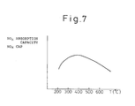
- Fig. 7 is a graph showing the capacity of absorption of NO x of the NO x absorbent
- Fig. 8 is a graph showing the characteristics of release of NO x
- Fig. 9 is a graph showing the change in the correction coefficient K
- Fig. 1 is an overall view of an internal combustion engine
- Fig. 2 is a diagram showing a map of a basic fuel injection time
- Fig. 3 is a diagram showing a correction coefficient K
- Fig. 4 is a graph
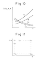
- Fig. 10 is a graph showing C 1 , C 2 , ⁇ , and ⁇ ;
- Fig. 11 is a diagram showing a map of the exhaust gas temperature T;
- Fig. 12 and Fig. 13 are flow charts showing a time interruption routine;
- Fig. 14 is a flow chart for calculating the fuel injection time TAU; and
- Fig. 15 is an overall view of an internal combustion engine showing another embodiment.
- Figure 1 shows a case where the present invention is applied to a gasoline engine.
- Fig. 1, 1 denotes an engine body; 2, a piston; 3, a combustion chamber; 4, a spark plug; 5, an intake valve; 6, an intake port; 7, an exhaust valve; and 8, an exhaust port, respectively.
- the intake port 6 is connected to a surge tank 10 via a corresponding branch pipe 9, and a fuel injector 11 injecting the fuel toward the interior of the intake port 6 is attached to each branch pipe 9.
- the surge tank 10 is connected to an air cleaner 13 via an intake duct 12, and a throttle valve 14 is disposed in the intake duct 12.
- the exhaust port 8 is connected via an exhaust manifold 15 and an exhaust pipe 16 to a casing 18 including a NO x absorbent 17.
- An electronic control unit 30 comprises a digital computer and is provided with a ROM (read only memory) 32, a RAM (random access memory) 33, a CPU (microprocessor) 34, an input port 35, and an output port 36, which are interconnected by a bidirectional bus 31.
- a pressure sensor 19 for generating an output voltage proportional to the absolute pressure in the surge tank 10.
- the output voltage of this pressure sensor 19 is input through an AD converter 37 to the input port 35.
- a temperature sensor 20 which generates an output voltage proportional to the temperature of the exhaust gas is attached in the exhaust pipe 16 upstream of the casing 18.
- the output voltage of this temperature sensor 20 is input through an AD converter 38 to the input port 35.
- the input port 35 is connected to it a rotational speed sensor 21 for generating an output pulse expressing the engine rotational speed.
- the output port 36 is connected through a corresponding drive circuit 39 to a spark plug 4 and fuel injector 11.
- the fuel injection time TAU is calculated based on for example the following equation.
- TAU TP•K
- TP is a basic fuel injection time
- K is a correction coefficient.
- the basic fuel injection time TP shows the fuel injection time necessary for bringing the air-fuel ratio of an air-fuel mixture fed into the engine cylinder to the stoichiometric air-fuel ratio.
- This basic fuel injection time TP is found in advance by experiments and is stored in advance in the ROM 32 in the form of a map as shown in Fig. 2 as the function of the absolute pressure PM in the surge tank 10 and the engine rotational speed N.
- the value of this correction coefficient K is predetermined in relation to the absolute pressure PM in the surge tank 10 and the engine rotational speed N.
- Figure 3 shows an embodiment of the value of the correction coefficient K.
- the value of the correction coefficient K is made a value smaller than 1.0, therefore at this time the air-fuel ratio of the air-fuel mixture fed into the engine cylinder is made lean.
- the value of the correction coefficient is made 1.0.
- the air-fuel ratio of the air-fuel mixture fed into the engine cylinder is made the stoichiometric air-fuel ratio. Further, in the region where the absolute pressure PM in the surge tank 10 becomes the highest, that is, in the engine full load operation region, the value of the correction coefficient is made a value larger than 1.0. Therefore, at this time, the air-fuel ratio of the air-fuel mixture fed into the engine cylinder is made rich.
- An internal combustion engine is usually operated most frequently with a low and medium load and therefore for the majority of the period of operation a lean air-fuel mixture is burned.
- Figure 4 schematically shows the concentration of representative components in the exhaust gas discharged from the combustion chamber 3.
- the concentration of the unburnt HC and CO in the exhaust gas discharged from the combustion chamber 3 is increased as the air-fuel ratio of the air-fuel mixture fed into the combustion chamber 3 becomes richer, and the concentration of the oxygen O 2 in the exhaust gas discharged from the combustion chamber 3 is increased as the air-fuel ratio of the air-fuel mixture fed into the combustion chamber 3 becomes leaner.
- the NO x absorbent 17 contained in the casing 18 uses, for example, alumina as a carrier.
- alumina as a carrier.
- alkali metals for example, potassium K, sodium Na, lithium Li, and cesium Cs
- alkali earths for example, barium Ba and calcium Ca
- rare earths for example, lanthanum La and yttrium Y and a precious metal such as platinum Pt are carried.
- this NO x absorbent 17 When referring to the ratio between the air and fuel (hydrocarbons) fed into the intake passage of the engine and the exhaust passage upstream of the NO x absorbent 17 as the air-fuel ratio of the inflowing exhaust gas flowing into the NO x absorbent 17, this NO x absorbent 17 performs the absorption and releasing function of NO x by absorbing the NO x when the air-fuel ratio of the inflowing exhaust gas is lean, while releasing the absorbed NO x when the concentration of oxygen in the inflowing exhaust gas falls.
- the air-fuel ratio of the inflowing exhaust gas coincides with the air-fuel ratio of the air-fuel mixture fed into the combustion chamber 3, and accordingly in this case, the NO x absorbent 17 absorbs the NO x when the air-fuel ratio of the air-fuel mixture fed into the combustion chamber 3 is lean and releases the absorbed NO x when the concentration of oxygen in the air-fuel mixture fed into the combustion chamber 3 is lowered.
- this NO x absorbent 17 When the above-mentioned NO x absorbent 17 is disposed in the exhaust passage of the engine, this NO x absorbent 17 actually performs the absorption and releasing function of NO x , but there are areas of the exact mechanism of this absorption and releasing function which are not clear. However, it can be considered that this absorption and releasing function is conducted by the mechanism as shown in Fig. 5. This mechanism will be explained by using as an example a case where platinum Pt and barium Ba are carried on the carrier, but a similar mechanism is obtained even if another precious metal, alkali metal, alkali earth, or rare earth is used.
- the concentration of oxygen in the inflowing exhaust gas is greatly increased.
- the oxygen O 2 is deposited on the surface of the platinum Pt in the form of O 2 - or O 2- .
- the NO in the inflowing exhaust gas reacts with the O 2 - or O 2- on the surface of the platinum Pt and becomes NO 2 (2NO + O 2 - 2NO 2 ).
- a part of the produced NO 2 is oxidized on the platinum Pt and absorbed into the absorbent. While bonding with the barium oxide BaO, it is diffused in the absorbent in the form of nitric acid ions NO 3 - as shown in Fig. 5(A). In this way, NO x is absorbed into the NO x absorbent 17.
- the NO 2 when the NO 2 no longer exists on the surface of the platinum Pt, the NO 2 is successively released from the absorbent. Accordingly, when the air-fuel ratio of the inflowing exhaust gas is made rich, the NO x is released from the NO x absorbent 19 in a short time.
- the NO x absorbent 17 has the function of a reduction catalyst, even if the air-fuel ratio of the inflowing exhaust gas is made the stoichiometric air-fuel ratio, the NO x released from the NO x absorbent 17 can be reduced. However, where the air-fuel ratio of the inflowing exhaust gas is made the stoichiometric air-fuel ratio, the NO x is released merely gradually from the NO x absorbent 17, and therefore a slightly long time is required for releasing all NO x absorbed in the NO x absorbent 17.
- the NO x it is also possible to reduce the NO x downstream of the NO x absorbent 17 in this way, but it is rather preferable that the NO x be reduced in the NO x absorbent 17. Accordingly, in the embodiment according to the present invention, when the NO x should be released from the NO x absorbent 17, the air-fuel ratio of the inflowing exhaust gas is made rich, whereby the NO x released from the NO x absorbent 17 is reduced in the NO x absorbent 17.
- the air-fuel mixture fed into the engine cylinder 3 is made rich and during high load operation, the air-fuel mixture is made the stoichiometric air-fuel ratio, so during the full load operation and the high load operation, the NO x is released from the NO x absorbent 17.
- the frequency of this full load operation or high load operation is small, then even if the NO x is released from the NO x absorbent 17 only during full load operation and high load operation, the absorption capacity of the NO x by the NO x absorbent 17 will end up becoming saturated during the time when a lean air-fuel mixture is burnt and therefore it will end up becoming impossible for the NO x absorbent 17 to absorb the NO x . Accordingly, in the embodiment according to the present invention, when a lean air-fuel mixture continues to be burnt, the air-fuel mixture fed into the combustion chamber 3 is cyclically made rich and during this time the NO x is released from the NO x absorbent 17.
- the amount of NO x which is absorbed in the NO x absorbent 17 is found and the air-fuel mixture is made rich when the amount of the NO x absorbed in the NO x absorbent 17 exceeds a predetermined allowable value. If the air-fuel mixture is made rich when the amount of the NO x absorbed in the NO x absorbent 17 exceeds a predetermined allowable value, then the NO x absorbing capacity of the NO x absorbent 17 will never become saturated, so the NO x will no longer be released into the atmosphere and, further, the frequency at which the air-fuel mixture is made rich can be reduced as well, so it is possible to suppress an increase in the amount of the fuel consumption.
- the amount of the NO x absorbed in the NO x absorbent 17 is estimated from the amount of NO x in the exhaust gas discharged from the engine. That is, the higher the rotational speed N of the engine, the larger the amount of exhaust gas discharged per unit time from the engine, so as the engine rotational speed N becomes higher, the amount of NO x discharged from the engine per unit time increases.
- the higher the engine load, that is, the higher the absolute pressure PM in the surge tank 10 the greater the amount of the exhaust gas discharged from the combustion chambers 3 and further the higher the combustion temperature, so the higher the engine load, that is, the higher the absolute pressure PM in the surge tank 10, the greater the amount of NO x discharged from the engine per unit time.
- Figure 6(A) shows the relationship between the amount of the NO x discharged from the engine per unit time, the absolute pressure PM in the surge tank 10, and the engine rotational speed N as found by experiments.
- the curves show the identical amounts of NO x .
- the amount of NO x discharged from the engine per unit time becomes larger the higher the absolute pressure PM in the surge tank 10 and becomes larger the higher the engine rotational speed N.
- the amount of NO x shown in Fig. 6(A) is stored in the ROM 32 in advance in the form of a map as shown in Fig. 6(B).
- Fig. 7 shows the relationship between the absorption capacity NO x CAP which can be absorbed by the NO x absorbent 17 and the temperature T of the exhaust gas, which represents the temperature of the NO x absorbent 17. If the temperature of the NO x absorbent 17 becomes lower, that is, the temperature T of the exhaust gas becomes lower, the oxidation action of the NO x (2NO + O 2 ⁇ 2NO 2 ) is weakened, and therefore the NO x absorption capacity NO x CAP is lowered.
- the NO x absorption capacity NO x CAP becomes larger between about 300°C to about 500°C.
- Fig. 8 shows the results of experiments on the amount of NO x released from the NO x absorbent 17 when switching the air-fuel ratio of the exhaust gas flowing into the NO x absorbent 17 from lean to rich.
- the solid line in Fig. 8 shows the state when the temperature of the NO x absorbent 17, that is, the temperature T of the exhaust gas, is high, while the broken line shows when the temperature of the NO x absorbent 17, that is, the temperature T of the exhaust gas, is low.
- the rate of decomposition of the NO x in the NO x absorbent 17 becomes faster the higher the temperature of the NO x absorbent 17. Therefore, when the temperature of the NO x absorbent 17 is high, as shown by the solid line in Fig.
- the value of the correction coefficient k with respect to the basic fuel injection time TP that is, the degree of richness of the air-fuel mixture
- the correction coefficient k is made to rise by a increments with each passing of the unit time until the time C reaches C 1 .
- the correction coefficient k is held constant, then when the time C exceeds C 2 , the correction coefficient k is made to descend in ⁇ decrements with each unit time.
- the values of these ⁇ , ⁇ , C 1 , and C 2 are set so that the pattern of change of the correction coefficient k becomes as close as possible to the pattern of change of the concentration of NO x shown by the solid line in Fig. 8.
- the pattern of change of the correction coefficient k when the temperature of the NO x absorbent 17, that is, the temperature T of the exhaust gas, is low is also set so that it becomes as close as possible to the pattern of change of the concentration of NO x when the temperature T of the exhaust gas is low, as shown by the broken line in Fig. 8.
- the pattern of change of the correction coefficient k in Fig. 9 like the broken line it is understood that it is sufficient to make both ⁇ and ⁇ smaller and make C 1 and C 2 larger. That is, to make the pattern of change of the correction coefficient k close to the pattern of change of the concentration of NO x shown in Fig.
- a temperature sensor 25 for detecting the temperature T of the exhaust gas and accordingly the NO x absorption capacity NO x CAP shown in Fig. 7 and the ⁇ , ⁇ , C 1 , and C 2 shown in Fig. 10 are determined based on the temperature T of the exhaust gas detected by this temperature sensor 25.
- the temperature T of the exhaust gas can be estimated from the absolute pressure PM in the surge tank 10 and the engine rotational speed N. Therefore, instead of providing the temperature sensor 25, it is possible to store the temperature T of the exhaust gas in the ROM 32 in advance in the form of a map as shown in Fig. 11 and determine the NO x absorption capacity NO x CAP and ⁇ , ⁇ , C 1 , and C 2 based on the temperature T of the exhaust gas obtained from this map.
- Figure 12 and Fig. 13 show a time interruption routine executed by interruption every predetermined time.
- step 100 it is judged if a NO x release flag showing that the NO x should be released from the NO x absorbent 17 is set or not.
- the routine proceeds to step 101, where it is judged if the correction coefficient K is smaller than 1.0, that is, if the operating state is one in which the air-fuel mixture should be made lean.
- K ⁇ 1.0 that is, when the operating state is one in which the air-fuel mixture should be made lean
- the routine proceeds to step 102, where the count D is made zero, then the routine proceeds to step 103.
- the NO x amount Nij discharged from the engine per unit time is calculated from the map shown in Fig. 6(B) based on the absolute pressure PM in the surge tank 10, detected by the pressure sensor 19, and the engine rotational speed N.
- the NO x amount Nij is multiplied by the interruption time interval At and the product Nij• ⁇ T is added to ⁇ NO x .
- the product Nij• ⁇ t shows the amount of the NO x discharged from the engine during the interruption time interval At.
- the NO x discharged from the engine is absorbed by the NO x absorbent 17, so ⁇ NO x shows the estimated value of the amount of NO x absorbed in the NO x absorbent 17.
- the NO x absorption capacity NO x CAP is calculated from the relationship shown in Fig. 7 based on the temperature T of the exhaust gas detected by the temperature sensor 25.
- NO x ⁇ NO x CAP the processing cycle is completed. At this time, a lean air-fuel mixture is burned and the NO x discharged from the engine is absorbed in the NO x absorbent 17.
- step 106 determines whether NO x absorption capacity of the NO x absorbent 17 is saturated. If it is judged at step 106 that ⁇ NO x > NO x CAP, that is, the NO x absorption capacity of the NO x absorbent 17 is saturated, the routine proceeds to step 107, where the NO x release flag is set. Next, at step 108, C 1 , C 2 , ⁇ , and ⁇ are calculated from the relation shown in Fig. 10 based on the temperature T of the exhaust gas and the processing cycle is ended. If the NO x release flag is set, at the next processing cycle, the routine proceeds from step 100 to step 109, where the count C is incremented by one. Next, at step 110, it is judged if the count C is smaller than C 1 .
- step 111 the routine proceeds to step 111, where ⁇ is added to the correction coefficient k.
- step 111 the processing cycle is ended.
- the action of addition of ⁇ to the correction coefficient k is performed continuously until C ⁇ C 1 . Accordingly, the value of the correction coefficient k during this time continues to increase as shown in Fig. 9.
- step 110 determines whether C ⁇ C 1 or C ⁇ C 1 or C ⁇ C 1 or C ⁇ C 1 or C ⁇ C 1 . If it is judged at step 110 that C ⁇ C 1 , the routine proceeds to step 112, where it is judged if the count C has become smaller than C 2 . When C ⁇ C 2 , the processing cycle is ended. Therefore, as shown in Fig. 9, the correction coefficient k is held constant until C ⁇ C 2 .
- step 112 when it is judged that C ⁇ C 2 , the routine proceeds to step 113, where ⁇ is subtracted from the correction coefficient k.
- step 113 it is judged if the correction coefficient k has become zero or a negative number.
- the processing cycle is ended. Accordingly, as shown in Fig. 9, the correction coefficient k is reduced until k ⁇ 0. Note that, as mentioned later, if k > 0, the air-fuel mixture fed to the combustion chamber 3 is made rich and during this time the degree of richness is changed by the pattern shown in Fig. 9.
- step 114 determines whether K ⁇ 0 or not. If it is judged at step 114 that K ⁇ 0, the routine proceeds to step 115, where the NO x release flag is reset.
- step 116 ⁇ NO x is made zero. That is, at this time, it is considered that all of the NO x which had been absorbed in the NO x absorbent 17 is released, so the estimated value ⁇ NO x of the NO x absorbed in the NO x absorbent 17 is made zero.
- step 117 the count C and the correction coefficient k are made zero and the processing cycle is ended.
- step 101 determines whether the engine operating state is one in which the air-fuel mixture should be made rich or the stoichiometric air-fuel ratio. If it is judged at step 101 that k ⁇ 1.0, that is, when the engine operating state is one in which the air-fuel mixture should be made rich or the stoichiometric air-fuel ratio, the routine proceeds to step 118, where the count D is incremented by one. Next, at step 119, it is judged if the count D has become larger than the constant value Do. When D > D 0 , the routine proceeds to step 120, where ⁇ NO x is made zero.
- Figure 14 shows the routine for calculation of the fuel injection time TAU. This routine is repeatedly executed.
- a basic fuel injection time TP is calculated from a map indicated in Fig. 2.
- the correction coefficient K shown in Fig. 3 which is determined in accordance with the operating state of the engine, is calculated.
- step 152 it is judged if the NO x release flag is set or not. When the NO x release flag is not set, the routine proceeds to step 153, where the correction coefficient K is made K t .
- step 155 K t is multiplied with the basic fuel injection time TP, whereby the fuel injection time TAU is calculated. Accordingly, at this time, the air-fuel mixture which is fed into the combustion chamber 3 is made lean, the stoichiometric air-fuel ratio, or rich in accordance with the operating state of the engine as shown in Fig. 3.
- step 152 when it is judged at step 152 that the NO x release flag is set, the routine proceeds to step 154, where K t is made the sum (k + 1) of correction coefficient k calculated by the routine shown in Fig. 12 and Fig. 13 and 1, then the routine proceeds to step 155.
- step 154 K t is made the sum (k + 1) of correction coefficient k calculated by the routine shown in Fig. 12 and Fig. 13 and 1, then the routine proceeds to step 155.
- the air-fuel mixture fed to the combustion chamber 3 is made rich, then the degree of richness is changed by the pattern shown in Fig. 9.
- Figure 15 shows another embodiment of the internal combustion engine.
- an outlet side of a casing 18 is connected through an exhaust pipe 22 to a catalytic converter 24 housing a three-way catalyst 23.
- This three-way catalyst 23 exhibits a high purification efficiency with respect to CO, HC, and NO x when the air-fuel ratio is maintained near the stoichiometric air-fuel ratio, but the three-way catalyst 23 also has a high purification efficiency with respect to NO x even when the air-fuel ratio becomes rich to a certain extent.
- a three-way catalyst 23 is provided downstream of the NO x absorbent 17 so as to remove the NO x using this characteristic.
- the air-fuel mixture fed into the engine cylinder is made rich to release the NO x from the NO x absorbent 17, the NO x absorbed in the NO x absorbent 17 is rapidly released from the NO x absorbent 17. At this time, the NO x is reduced during its release, but there is a possibility that all of the NO x will not be reduced. If the three-way catalyst 23 is disposed downstream of the NO x absorbent 17, however, the NO x which could not be reduced at the time of the release of the NO x is reduced by the three-way catalyst 23. Accordingly, by disposing the three-way catalyst 23 downstream of the NO x absorbent 17, it becomes possible to improve considerably the purification performance of the NO x .
- NO x absorbent 17 comprised of at least one of an alkali metal, alkali earth, and rare earth and a precious metal carried on alumina.
- a NO x absorbent 17 it is also possible to use a complex oxide of an alkali earth and copper, that is, a NO x absorbent of the Ba-Cu-O system.
- a complex oxide of an alkali earth and copper use may be made for example of MnO 2 •BaCuO 2 . In this case, it is also possible to add platinum Pt or cerium Ce.
- the copper Cu performs the same catalytic function as the platinum Pt in the NO x absorbent 17 spoken of up to now.
- the air-fuel ratio is lean
- the NO x is oxidized by the copper (2NO + O 2 ⁇ 2NO 2 ) and dispersed in the absorbent in the form of nitric acid ions NO 3 - .
Landscapes
- Engineering & Computer Science (AREA)
- Chemical & Material Sciences (AREA)
- Combustion & Propulsion (AREA)
- Mechanical Engineering (AREA)
- General Engineering & Computer Science (AREA)
- Analytical Chemistry (AREA)
- Chemical Kinetics & Catalysis (AREA)
- General Chemical & Material Sciences (AREA)
- Oil, Petroleum & Natural Gas (AREA)
- Environmental & Geological Engineering (AREA)
- Biomedical Technology (AREA)
- Health & Medical Sciences (AREA)
- Materials Engineering (AREA)
- Exhaust Gas After Treatment (AREA)
Claims (21)
- Un dispositif d'épuration sur échappement d'un moteur à combustion interne, comportant, dans un passage d'échappement moteur, un absorbant de NOx, absorbant les NOx lorsque le rapport air-carburant des gaz d'échappement entrants est pauvre et relâchant les NOx absorbés lorsque le rapport air-carburant dans les gaz d'échappement entrants devient riche, et doté de moyens de détection de température pour appréhender la température, représentant la température de l'absorbant de NOx et de moyens de commande de relâchement de NOx pour rendre riches les gaz d'échappement entrants dans l'absorbant de NOx, lorsque les NOx doivent être libérés de l'absorbant de NOx et lesdits moyens de commande de relâchement de NOx augmentant le degré de richesse et/ou raccourcissant le temps pendant lequel le rapport est rendu riche, lorsque la température qui représente la température de l'absorbant de NOx augmente.
- Un dispositif d'épuration sur échappement d'un moteur à combustion interne selon la revendication 1, dans lequel lesdits moyens de contrôle de relâchement de NOx augmentent le degré de richesse et raccourcissent la durée pendant laquelle le rapport est plus riche lorsque la température représentant la température de l'absorbant de NOx augmente.
- Un dispositif d'épuration sur échappement d'un moteur à combustion interne selon la revendication 2, dans lequel lesdits moyens de commande de relâchement de NOx changent le degré de richesse suivant un schéma de changement qui ressemble au schéma de changement de la quantité de NOx relâchée par l'absorbant de NOx lorsqu'il y a relâchement de NOx depuis l'absorbant de NOx.
- Un dispositif d'épuration sur échappement d'un moteur à combustion interne selon la revendication 3, dans lequel lesdits moyens de commande de relâchement de NOx élévent le degré de richesse à un degré de richesse prédéterminé par un taux prédéterminé d'élévation, puis abaissent le degré de richesse par un taux prédéterminé d'abaissement, lorsque le relâchement de NOx par l'absorbant de NOx se produit et augmentent le taux d'élévation, le degré prédéterminé de richesse et le taux d'abaissement, lorsque la température représentant la température de l'absorbant de NOx augmente.
- Un dispositif d'épuration sur échappement d'un moteur à combustion interne selon la revendication 1, dans lequel la température représentant l'absorbant de NOx est la température des gaz d'échappement entrants dans l'absorbant de NOx.
- Un dispositif d'épuration sur échappement d'un moteur à combustion interne selon la revendication 5, dans lequel il est prévu une mémoire dans laquelle est mémorisée au préalable la température des gaz d'échappement entrants dans l'absorbant de NOx en fonction de la charge du moteur et de la vitesse de rotation du moteur, et dans lequel la température représentant la température de l'absorbant de NOx est stockée en mémoire.
- Un dispositif d'épuration sur échappement d'un moteur à combustion interne selon la revendication 1, dans lequel lesdits moyens de commande de relâchement de NOx rendent riche le rapport air-carburant du mélange air-carburant introduit dans la chambre de combustion lorsqu'il y a dégagement de NOx par l'absorbant de NOx.
- Un dispositif d'épuration sur échappement d'un moteur à combustion interne selon la revendication 1, dans lequel les moyens d'estimation de NOx sont prévus pour estimer la quantité de NOx absorbée dans ledit absorbant de NOx, et dans lequel les moyens de commande de relâchement de NOx rendent riche le rapport air-carburant des gaz d'échappement entrants dans l'absorbant de NOx, pour relâcher le NOx par l'absorbant de NOx lorsque la quantité de NOx estimée être absorbée dans l'absorbant de NOx, par les moyens d'estimation de NOx, dépasse un niveau d'acceptation prédéterminé.
- Un dispositif d'épuration sur échappement d'un moteur à combustion interne selon la revendication 8, dans lequel lesdits moyens d'estimation de NOx estiment la quantité de NOx absorbée dans l'absorbant de NOx en se basant sur la quantité de NOx déchargée de la chambre de combustion dans le passage d'échappement moteur.
- Un dispositif d'épuration sur échappement d'un moteur à combustion interne selon la revendication 9, dans lequel lesdits moyens d'estimation de NOx sont constitués de moyens de calcul de NOx pour calculer la quantité de NOx déchargée par unité de temps à partir du moteur vers le passage d'échappement moteur, selon la charge moteur et la vitesse de rotation moteur, et des moyens d'addition cumulatifs pour ajouter de façon cumulative les quantités de NOx calculées par les moyens de calcul de NOx.
- Un dispositif d'épuration sur échappement d'un moteur à combustion interne selon la revendication 10, dans lequel lesdits moyens de calcul de NOx sont dotés d'une mémoire dans laquelle est au préalable mémorisée la quantité de NOx déchargée par unité de temps par le moteur vers le passage d'échappement moteur, en fonction de la charge moteur et de la vitesse de rotation du moteur, et dans lequel les moyens d'addition cumulatifs effectuent une addition cumulative des quantités de NOx stockées dans la mémoire et déterminées par la charge moteur et la vitesse de rotation moteur.
- Un dispositif d'épuration sur échappement d'un moteur à combustion interne selon la revendication 10, dans lequel il est prévu un clapet d'étranglement disposé dans le passage d'admission du moteur pour moduler la charge moteur, et la dépression, à l'intérieur du passage d'admission moteur en aval du clapet d'étranglement, est utilisée comme valeur représentative de la charge moteur.
- Un dispositif d'épuration sur échappement d'un moteur à combustion interne selon la revendication 8, dans lequel ledit niveau d'acceptation est la capacité d'absorption maximale en NOx de l'absorbant de NOx.
- Un dispositif d'épuration sur échappement d'un moteur à combustion interne selon la revendication 13, dans lequel ledit niveau d'acceptation est une fonction de la température représentant la température de l'absorbant NOx.
- Un dispositif d'épuration sur échappement d'un moteur à combustion interne selon la revendication 8, dans lequel lesdits moyens d'estimation de NOx amènent à la valeur zéro la quantité de NOx estimée comme étant absorbée par l'absorbant de NOx lorsque le rapport le rapport air-carburant des gaz d'échappement s'écoulant dans l'absorbant de NOx est rendu riche, suite au fait que la quantité de NOx estimée par les moyens d'estimation de NOx dépasse le niveau d'acceptation.
- Un dispositif d'épuration sur échappement d'un moteur à combustion interne selon la revendication 8, dans lequel lesdits moyens de commande de rapport air-carburant sont prévus pour rendre riche le rapport air-carburant du mélange air-carburant amené à la chambre de combustion, en fonction de l'état de fonctionnement du moteur, indépendamment du fait que la quantité de NOx estimée par les moyens d'estimation de NOx dépasse le niveau d'acceptation
- Un dispositif d'épuration sur échappement d'un moteur à combustion interne selon la revendication 16, dans lequel lesdits moyens de commande du rapport air-carburant amènent à un niveau riche le rapport air-carburant du mélange air-carburant amené dans la chambre de combustion, lorsque la charge moteur dépasse une charge prédéterminée.
- Un dispositif d'épuration sur échappement d'un moteur à combustion interne selon la revendication 17, dans lequel lesdits moyens d'estimation des NOx mettent à la valeur zéro la quantité de NOx estimée comme étant absorbée dans l'absorbant de NOx lorsque le rapport air-carburant, du mélange air-carburant, est rendu riche pendant une durée supérieure à une durée prédéterminée.
- Un dispositif d'épuration sur échappement d'un moteur à combustion interne selon la revendication 1, dans lequel l'absorbant de NOx comprend au moins une substance sélectionnée parmi des métaux alcalins tels que le potassium, sodium, lithium et le césium, des alcalino-terreux tels que le baryum et le calcium et des terres rares, telles que lanthane, l'yttrium et le platine.
- Un dispositif d'épuration sur échappement d'un moteur à combustion interne selon la revendication 1, dans lequel l'absorbant de NOx comprend un oxyde composite de baryum et de cuivre.
- Un dispositif d'épuration sur échappement d'un moteur à combustion interne selon la revendication 1, dans lequel un catalyseur trois voies est disposé dans le passage d'échappement moteur, en aval de l'absorbant de NOx.
Applications Claiming Priority (7)
| Application Number | Priority Date | Filing Date | Title |
|---|---|---|---|
| JP177666/92 | 1992-06-12 | ||
| JP17766692 | 1992-06-12 | ||
| JP17766692 | 1992-06-12 | ||
| JP19021492 | 1992-06-25 | ||
| JP190214/92 | 1992-06-25 | ||
| JP4190214A JP2722951B2 (ja) | 1992-06-25 | 1992-06-25 | 内燃機関の排気浄化装置 |
| PCT/JP1993/000777 WO1993025805A1 (fr) | 1992-06-12 | 1993-06-10 | Systeme de limitation d'emission de gaz d'echappement pour moteur a combustion interne |
Publications (3)
| Publication Number | Publication Date |
|---|---|
| EP0598916A1 EP0598916A1 (fr) | 1994-06-01 |
| EP0598916A4 EP0598916A4 (fr) | 1998-08-19 |
| EP0598916B1 true EP0598916B1 (fr) | 1999-09-15 |
Family
ID=26498143
Family Applications (1)
| Application Number | Title | Priority Date | Filing Date |
|---|---|---|---|
| EP93913501A Expired - Lifetime EP0598916B1 (fr) | 1992-06-12 | 1993-06-10 | Systeme de limitation d'emission de gaz d'echappement pour moteur a combustion interne |
Country Status (4)
| Country | Link |
|---|---|
| US (1) | US5450722A (fr) |
| EP (1) | EP0598916B1 (fr) |
| DE (1) | DE69326417T2 (fr) |
| WO (1) | WO1993025805A1 (fr) |
Families Citing this family (77)
| Publication number | Priority date | Publication date | Assignee | Title |
|---|---|---|---|---|
| EP0666102B1 (fr) * | 1994-02-04 | 2001-11-07 | Toyota Jidosha Kabushiki Kaisha | Procédé pour la préparation d'un catalyseur pour la purification de gaz d'échappement |
| US5968462A (en) * | 1994-02-04 | 1999-10-19 | Toyota Jidosha Kabushiki Kaisha | Process for purifying exhaust gases |
| FR2728300B1 (fr) * | 1994-12-19 | 1997-03-14 | Peugeot | Dispositif de traitement des gaz d'echappement d'un moteur a allumage par compression comportant un catalyseur et un adsorbeur d'oxydes d'azote places dans le collecteur d'echappement |
| US6161378A (en) | 1996-06-10 | 2000-12-19 | Hitachi, Ltd. | Exhaust gas purification apparatus of internal combustion engine and catalyst for purifying exhaust gas internal combustion engine |
| AU742434B2 (en) * | 1996-06-10 | 2002-01-03 | Hitachi Limited | Exhaust gas purification apparatus of internal combustion engine and catalyst for purifying exhaust gas of internal combustion engine |
| JP2871615B2 (ja) * | 1996-09-09 | 1999-03-17 | トヨタ自動車株式会社 | 内燃機関の排気浄化装置 |
| JP3965711B2 (ja) | 1996-10-25 | 2007-08-29 | 株式会社日立製作所 | 窒素酸化物の浄化触媒及び浄化方法 |
| US5894725A (en) * | 1997-03-27 | 1999-04-20 | Ford Global Technologies, Inc. | Method and apparatus for maintaining catalyst efficiency of a NOx trap |
| US5832722A (en) * | 1997-03-31 | 1998-11-10 | Ford Global Technologies, Inc. | Method and apparatus for maintaining catalyst efficiency of a NOx trap |
| CN1095028C (zh) | 1997-04-09 | 2002-11-27 | 发射技术有限公司 | 监控NOx存储器的方法和设备 |
| DE19730403C1 (de) * | 1997-07-16 | 1998-10-22 | Daimler Benz Ag | Mehrzylindrige, luftverdichtende Einspritzbrennkraftmaschine |
| DE19739848A1 (de) * | 1997-09-11 | 1999-03-18 | Bosch Gmbh Robert | Brennkraftmaschine insbesondere für ein Kraftfahrzeug |
| DE19741079C2 (de) * | 1997-09-18 | 2001-10-18 | Ford Global Tech Inc | Verfahren zur Regeneration einer Stickoxidfalle im Abgassystem eines Verbrennungsmotors |
| US6148612A (en) * | 1997-10-13 | 2000-11-21 | Denso Corporation | Engine exhaust gas control system having NOx catalyst |
| FR2773843B1 (fr) * | 1998-01-19 | 2000-03-17 | Renault | Procede de commande de purge d'un pot catalytique de traitement des gaz d'echappement d'un moteur a combustion interne |
| US6244046B1 (en) | 1998-07-17 | 2001-06-12 | Denso Corporation | Engine exhaust purification system and method having NOx occluding and reducing catalyst |
| JP3854013B2 (ja) * | 1999-06-10 | 2006-12-06 | 三菱電機株式会社 | 内燃機関の排出ガス浄化装置 |
| JP3613083B2 (ja) * | 1999-08-09 | 2005-01-26 | 株式会社日立製作所 | 排気浄化制御装置 |
| US6308515B1 (en) | 2000-03-17 | 2001-10-30 | Ford Global Technologies, Inc. | Method and apparatus for accessing ability of lean NOx trap to store exhaust gas constituent |
| US6499293B1 (en) | 2000-03-17 | 2002-12-31 | Ford Global Technologies, Inc. | Method and system for reducing NOx tailpipe emissions of a lean-burn internal combustion engine |
| US6843051B1 (en) | 2000-03-17 | 2005-01-18 | Ford Global Technologies, Llc | Method and apparatus for controlling lean-burn engine to purge trap of stored NOx |
| US6487850B1 (en) | 2000-03-17 | 2002-12-03 | Ford Global Technologies, Inc. | Method for improved engine control |
| US6860100B1 (en) | 2000-03-17 | 2005-03-01 | Ford Global Technologies, Llc | Degradation detection method for an engine having a NOx sensor |
| US6539704B1 (en) | 2000-03-17 | 2003-04-01 | Ford Global Technologies, Inc. | Method for improved vehicle performance |
| US6434930B1 (en) | 2000-03-17 | 2002-08-20 | Ford Global Technologies, Inc. | Method and apparatus for controlling lean operation of an internal combustion engine |
| US6487849B1 (en) | 2000-03-17 | 2002-12-03 | Ford Global Technologies, Inc. | Method and apparatus for controlling lean-burn engine based upon predicted performance impact and trap efficiency |
| US6477832B1 (en) | 2000-03-17 | 2002-11-12 | Ford Global Technologies, Inc. | Method for improved performance of a vehicle having an internal combustion engine |
| US6327847B1 (en) | 2000-03-17 | 2001-12-11 | Ford Global Technologies, Inc. | Method for improved performance of a vehicle |
| US6708483B1 (en) | 2000-03-17 | 2004-03-23 | Ford Global Technologies, Llc | Method and apparatus for controlling lean-burn engine based upon predicted performance impact |
| US6308697B1 (en) | 2000-03-17 | 2001-10-30 | Ford Global Technologies, Inc. | Method for improved air-fuel ratio control in engines |
| US6481199B1 (en) | 2000-03-17 | 2002-11-19 | Ford Global Technologies, Inc. | Control for improved vehicle performance |
| US6360530B1 (en) | 2000-03-17 | 2002-03-26 | Ford Global Technologies, Inc. | Method and apparatus for measuring lean-burn engine emissions |
| US6438944B1 (en) | 2000-03-17 | 2002-08-27 | Ford Global Technologies, Inc. | Method and apparatus for optimizing purge fuel for purging emissions control device |
| US6374597B1 (en) | 2000-03-17 | 2002-04-23 | Ford Global Technologies, Inc. | Method and apparatus for accessing ability of lean NOx trap to store exhaust gas constituent |
| US6594989B1 (en) | 2000-03-17 | 2003-07-22 | Ford Global Technologies, Llc | Method and apparatus for enhancing fuel economy of a lean burn internal combustion engine |
| US6810659B1 (en) * | 2000-03-17 | 2004-11-02 | Ford Global Technologies, Llc | Method for determining emission control system operability |
| US6427437B1 (en) | 2000-03-17 | 2002-08-06 | Ford Global Technologies, Inc. | Method for improved performance of an engine emission control system |
| US6629453B1 (en) | 2000-03-17 | 2003-10-07 | Ford Global Technologies, Llc | Method and apparatus for measuring the performance of an emissions control device |
| US6370868B1 (en) | 2000-04-04 | 2002-04-16 | Ford Global Technologies, Inc. | Method and system for purge cycle management of a lean NOx trap |
| US6389803B1 (en) | 2000-08-02 | 2002-05-21 | Ford Global Technologies, Inc. | Emission control for improved vehicle performance |
| DE10044411A1 (de) * | 2000-09-08 | 2002-03-21 | Bayerische Motoren Werke Ag | Verfahren zur Steuerung eines Verbrennungsmotors bei einem Regenerationszyklus |
| US6691507B1 (en) | 2000-10-16 | 2004-02-17 | Ford Global Technologies, Llc | Closed-loop temperature control for an emission control device |
| DE10054005A1 (de) | 2000-11-01 | 2002-05-08 | Daimler Chrysler Ag | Verfahren zum Betrieb einer Abgasreinigungsanlage mit Stickoxidspeicher |
| US6694244B2 (en) | 2001-06-19 | 2004-02-17 | Ford Global Technologies, Llc | Method for quantifying oxygen stored in a vehicle emission control device |
| US6546718B2 (en) | 2001-06-19 | 2003-04-15 | Ford Global Technologies, Inc. | Method and system for reducing vehicle emissions using a sensor downstream of an emission control device |
| US6453666B1 (en) | 2001-06-19 | 2002-09-24 | Ford Global Technologies, Inc. | Method and system for reducing vehicle tailpipe emissions when operating lean |
| US6463733B1 (en) | 2001-06-19 | 2002-10-15 | Ford Global Technologies, Inc. | Method and system for optimizing open-loop fill and purge times for an emission control device |
| US6490860B1 (en) | 2001-06-19 | 2002-12-10 | Ford Global Technologies, Inc. | Open-loop method and system for controlling the storage and release cycles of an emission control device |
| US6604504B2 (en) | 2001-06-19 | 2003-08-12 | Ford Global Technologies, Llc | Method and system for transitioning between lean and stoichiometric operation of a lean-burn engine |
| US6467259B1 (en) | 2001-06-19 | 2002-10-22 | Ford Global Technologies, Inc. | Method and system for operating dual-exhaust engine |
| US6691020B2 (en) | 2001-06-19 | 2004-02-10 | Ford Global Technologies, Llc | Method and system for optimizing purge of exhaust gas constituent stored in an emission control device |
| US6553754B2 (en) | 2001-06-19 | 2003-04-29 | Ford Global Technologies, Inc. | Method and system for controlling an emission control device based on depletion of device storage capacity |
| US6487853B1 (en) | 2001-06-19 | 2002-12-03 | Ford Global Technologies. Inc. | Method and system for reducing lean-burn vehicle emissions using a downstream reductant sensor |
| US6615577B2 (en) | 2001-06-19 | 2003-09-09 | Ford Global Technologies, Llc | Method and system for controlling a regeneration cycle of an emission control device |
| US6650991B2 (en) | 2001-06-19 | 2003-11-18 | Ford Global Technologies, Llc | Closed-loop method and system for purging a vehicle emission control |
| US6502387B1 (en) | 2001-06-19 | 2003-01-07 | Ford Global Technologies, Inc. | Method and system for controlling storage and release of exhaust gas constituents in an emission control device |
| JP3810663B2 (ja) * | 2001-09-19 | 2006-08-16 | 三菱電機株式会社 | 内燃機関の排気ガス浄化方法、及び排気ガス浄化装置 |
| US6679224B2 (en) | 2001-11-06 | 2004-01-20 | Southwest Research Institute | Method and apparatus for operating a diesel engine under stoichiometric or slightly fuel-rich conditions |
| US6553757B1 (en) * | 2001-11-19 | 2003-04-29 | Ford Global Technologies, Llc | NOx purge air/fuel ratio selection |
| US6574953B1 (en) * | 2001-11-29 | 2003-06-10 | Ford Global Technologies, Llc | NOx purge air/fuel ratio selection |
| US6736120B2 (en) * | 2002-06-04 | 2004-05-18 | Ford Global Technologies, Llc | Method and system of adaptive learning for engine exhaust gas sensors |
| US6868827B2 (en) | 2002-06-04 | 2005-03-22 | Ford Global Technologies, Llc | Method for controlling transitions between operating modes of an engine for rapid heating of an emission control device |
| US6715462B2 (en) | 2002-06-04 | 2004-04-06 | Ford Global Technologies, Llc | Method to control fuel vapor purging |
| US7111450B2 (en) | 2002-06-04 | 2006-09-26 | Ford Global Technologies, Llc | Method for controlling the temperature of an emission control device |
| US6758185B2 (en) | 2002-06-04 | 2004-07-06 | Ford Global Technologies, Llc | Method to improve fuel economy in lean burn engines with variable-displacement-like characteristics |
| US6925982B2 (en) | 2002-06-04 | 2005-08-09 | Ford Global Technologies, Llc | Overall scheduling of a lean burn engine system |
| US7032572B2 (en) | 2002-06-04 | 2006-04-25 | Ford Global Technologies, Llc | Method for controlling an engine to obtain rapid catalyst heating |
| US6735938B2 (en) | 2002-06-04 | 2004-05-18 | Ford Global Technologies, Llc | Method to control transitions between modes of operation of an engine |
| US6745747B2 (en) | 2002-06-04 | 2004-06-08 | Ford Global Technologies, Llc | Method for air-fuel ratio control of a lean burn engine |
| US6568177B1 (en) | 2002-06-04 | 2003-05-27 | Ford Global Technologies, Llc | Method for rapid catalyst heating |
| US6769398B2 (en) * | 2002-06-04 | 2004-08-03 | Ford Global Technologies, Llc | Idle speed control for lean burn engine with variable-displacement-like characteristic |
| US6736121B2 (en) | 2002-06-04 | 2004-05-18 | Ford Global Technologies, Llc | Method for air-fuel ratio sensor diagnosis |
| US7168239B2 (en) | 2002-06-04 | 2007-01-30 | Ford Global Technologies, Llc | Method and system for rapid heating of an emission control device |
| US6725830B2 (en) | 2002-06-04 | 2004-04-27 | Ford Global Technologies, Llc | Method for split ignition timing for idle speed control of an engine |
| DE60230977D1 (de) | 2002-07-31 | 2009-03-12 | Umicore Ag & Co Kg | Verfahren zur Regenerierung eines Stickoxid-Speicherkatalysators |
| JP4135428B2 (ja) * | 2002-08-01 | 2008-08-20 | 日産自動車株式会社 | 内燃機関の排気浄化装置及び方法 |
| WO2010089901A1 (fr) * | 2009-02-06 | 2010-08-12 | トヨタ自動車株式会社 | Dispositif de nettoyage d'échappement pour moteur à combustion interne |
Family Cites Families (20)
| Publication number | Priority date | Publication date | Assignee | Title |
|---|---|---|---|---|
| JPS53115687A (en) * | 1977-03-18 | 1978-10-09 | Matsushita Electric Ind Co Ltd | Gas purifying catalytic member |
| JPS60182325A (ja) * | 1984-02-28 | 1985-09-17 | Toyota Motor Corp | 内燃機関のΝOx低減方法 |
| JPS61111127A (ja) * | 1984-11-06 | 1986-05-29 | Ebara Infilco Co Ltd | 排ガスの処理方法 |
| JPS61112715A (ja) * | 1984-11-08 | 1986-05-30 | Toyota Motor Corp | デイ−ゼル機関の排気浄化装置 |
| JPS6297630A (ja) * | 1985-10-24 | 1987-05-07 | Nippon Shokubai Kagaku Kogyo Co Ltd | 窒素酸化物含有ガスから窒素酸化物を除去する方法 |
| JPS62106826A (ja) * | 1985-11-06 | 1987-05-18 | Nippon Shokubai Kagaku Kogyo Co Ltd | デイ−ゼル排ガス中の窒素酸化物を除去する方法 |
| JPS62117620A (ja) * | 1985-11-19 | 1987-05-29 | Nippon Shokubai Kagaku Kogyo Co Ltd | ガソリンエンジン排ガス中の窒素酸化物を除去する方法 |
| US4656829A (en) * | 1986-01-27 | 1987-04-14 | General Motors Corporation | System for predicting catalytic converter temperature |
| JPS63134810A (ja) * | 1986-11-25 | 1988-06-07 | Isuzu Motors Ltd | パテイキユレ−トトラツプの再生装置 |
| JPS6430643A (en) * | 1987-07-24 | 1989-02-01 | Matsushita Electric Industrial Co Ltd | Catalyst for purifying exhaust gas |
| JPS6456816A (en) * | 1987-08-27 | 1989-03-03 | Sumitomo Metal Ind | Heating method for molten steel in ladle |
| JPH02149715A (ja) * | 1988-11-30 | 1990-06-08 | Mazda Motor Corp | エンジン排気ガス異臭発生防止装置 |
| JPH088975B2 (ja) * | 1989-10-20 | 1996-01-31 | 松下電器産業株式会社 | No▲下×▼除去装置 |
| JPH03194113A (ja) * | 1989-12-21 | 1991-08-23 | Mazda Motor Corp | エンジンの排気浄化装置 |
| JP2543736Y2 (ja) * | 1989-12-27 | 1997-08-13 | トヨタ自動車株式会社 | 内燃機関の排気浄化装置 |
| JPH041617A (ja) * | 1990-04-18 | 1992-01-07 | Nec Corp | 積層構造 |
| JP3046051B2 (ja) * | 1990-09-28 | 2000-05-29 | マツダ株式会社 | エンジンの排気ガス浄化装置 |
| KR950004533B1 (ko) * | 1990-11-30 | 1995-05-02 | 미쯔비시 지도샤 고교 가부시끼가이샤 | 디젤엔진의 배기 가스 처리 장치 |
| JP2663720B2 (ja) * | 1990-12-26 | 1997-10-15 | トヨタ自動車株式会社 | ディーゼルエンジンの排気浄化装置 |
| JP2887933B2 (ja) * | 1991-03-13 | 1999-05-10 | トヨタ自動車株式会社 | 内燃機関の排気浄化装置 |
-
1993
- 1993-06-10 WO PCT/JP1993/000777 patent/WO1993025805A1/fr not_active Ceased
- 1993-06-10 EP EP93913501A patent/EP0598916B1/fr not_active Expired - Lifetime
- 1993-06-10 DE DE69326417T patent/DE69326417T2/de not_active Expired - Lifetime
- 1993-06-10 US US08/196,144 patent/US5450722A/en not_active Expired - Lifetime
Also Published As
| Publication number | Publication date |
|---|---|
| EP0598916A1 (fr) | 1994-06-01 |
| WO1993025805A1 (fr) | 1993-12-23 |
| DE69326417D1 (de) | 1999-10-21 |
| US5450722A (en) | 1995-09-19 |
| DE69326417T2 (de) | 2000-04-13 |
| EP0598916A4 (fr) | 1998-08-19 |
Similar Documents
| Publication | Publication Date | Title |
|---|---|---|
| EP0598916B1 (fr) | Systeme de limitation d'emission de gaz d'echappement pour moteur a combustion interne | |
| US5433074A (en) | Exhaust gas purification device for an engine | |
| EP0585900B1 (fr) | Appareil de dépollution de gaz d'échappement de moteur | |
| EP0598917B1 (fr) | Systeme de limitation d'emission de gaz d'echappement pour moteur a combustion interne | |
| US5471836A (en) | Exhaust purification device of internal combustion engine | |
| EP0560991B1 (fr) | Dispositif pour purifier les gaz d'echappement d'un moteur a combustion interne | |
| US5577382A (en) | Exhaust purification device of internal combustion engine | |
| EP0573672B1 (fr) | Dispositif limitant l'emission des gaz d'echappement dans un moteur a combustion interne | |
| US5473890A (en) | Exhaust purification device of internal combustion engine | |
| EP0629771A2 (fr) | Dispositif de purification des gaz d'échappement d'un moteur | |
| US5388403A (en) | Exhaust gas purification device for an engine | |
| EP1176298A2 (fr) | Système et méthode de commande de l'émission des gaz d'échappement pour moteurs à combustion interne | |
| JP3353650B2 (ja) | 内燃機関の触媒被毒再生装置 | |
| JPWO1993025806A1 (ja) | 内燃機関の排気浄化装置 | |
| JP2658756B2 (ja) | 内燃機関の排気浄化装置 | |
| JP2998481B2 (ja) | 内燃機関の排気浄化装置 | |
| JP2743751B2 (ja) | 内燃機関の排気浄化装置 | |
| JP2689829B2 (ja) | 内燃機関の排気浄化装置 | |
| JP2914067B2 (ja) | 内燃機関の排気浄化装置 | |
| JP3123513B2 (ja) | 内燃機関の排気浄化装置 | |
| JP3509584B2 (ja) | 内燃機関の排気浄化装置 | |
| JPH10176522A (ja) | 内燃機関の排気浄化装置 | |
| JPH07166913A (ja) | 内燃機関の排気浄化装置 | |
| JP3186393B2 (ja) | 内燃機関の排気浄化装置 | |
| JPWO1993012863A1 (ja) | 内燃機関の排気浄化装置 |
Legal Events
| Date | Code | Title | Description |
|---|---|---|---|
| PUAI | Public reference made under article 153(3) epc to a published international application that has entered the european phase |
Free format text: ORIGINAL CODE: 0009012 |
|
| 17P | Request for examination filed |
Effective date: 19940209 |
|
| AK | Designated contracting states |
Kind code of ref document: A1 Designated state(s): DE FR GB |
|
| A4 | Supplementary search report drawn up and despatched | ||
| AK | Designated contracting states |
Kind code of ref document: A4 Designated state(s): DE FR GB |
|
| GRAG | Despatch of communication of intention to grant |
Free format text: ORIGINAL CODE: EPIDOS AGRA |
|
| 17Q | First examination report despatched |
Effective date: 19981125 |
|
| GRAG | Despatch of communication of intention to grant |
Free format text: ORIGINAL CODE: EPIDOS AGRA |
|
| GRAG | Despatch of communication of intention to grant |
Free format text: ORIGINAL CODE: EPIDOS AGRA |
|
| GRAH | Despatch of communication of intention to grant a patent |
Free format text: ORIGINAL CODE: EPIDOS IGRA |
|
| GRAH | Despatch of communication of intention to grant a patent |
Free format text: ORIGINAL CODE: EPIDOS IGRA |
|
| GRAA | (expected) grant |
Free format text: ORIGINAL CODE: 0009210 |
|
| AK | Designated contracting states |
Kind code of ref document: B1 Designated state(s): DE FR GB |
|
| ET | Fr: translation filed | ||
| REF | Corresponds to: |
Ref document number: 69326417 Country of ref document: DE Date of ref document: 19991021 |
|
| PLBE | No opposition filed within time limit |
Free format text: ORIGINAL CODE: 0009261 |
|
| STAA | Information on the status of an ep patent application or granted ep patent |
Free format text: STATUS: NO OPPOSITION FILED WITHIN TIME LIMIT |
|
| 26N | No opposition filed | ||
| REG | Reference to a national code |
Ref country code: GB Ref legal event code: IF02 |
|
| PGFP | Annual fee paid to national office [announced via postgrant information from national office to epo] |
Ref country code: DE Payment date: 20120607 Year of fee payment: 20 |
|
| PGFP | Annual fee paid to national office [announced via postgrant information from national office to epo] |
Ref country code: FR Payment date: 20120619 Year of fee payment: 20 Ref country code: GB Payment date: 20120606 Year of fee payment: 20 |
|
| REG | Reference to a national code |
Ref country code: DE Ref legal event code: R071 Ref document number: 69326417 Country of ref document: DE |
|
| REG | Reference to a national code |
Ref country code: DE Ref legal event code: R071 Ref document number: 69326417 Country of ref document: DE |
|
| REG | Reference to a national code |
Ref country code: GB Ref legal event code: PE20 Expiry date: 20130609 |
|
| PG25 | Lapsed in a contracting state [announced via postgrant information from national office to epo] |
Ref country code: GB Free format text: LAPSE BECAUSE OF EXPIRATION OF PROTECTION Effective date: 20130609 Ref country code: DE Free format text: LAPSE BECAUSE OF EXPIRATION OF PROTECTION Effective date: 20130611 |