EP0599190A2 - Dispositif de régulation de la vitesse de moteurs - Google Patents
Dispositif de régulation de la vitesse de moteurs Download PDFInfo
- Publication number
- EP0599190A2 EP0599190A2 EP93118534A EP93118534A EP0599190A2 EP 0599190 A2 EP0599190 A2 EP 0599190A2 EP 93118534 A EP93118534 A EP 93118534A EP 93118534 A EP93118534 A EP 93118534A EP 0599190 A2 EP0599190 A2 EP 0599190A2
- Authority
- EP
- European Patent Office
- Prior art keywords
- signal
- period
- motor
- disturbance
- control apparatus
- Prior art date
- Legal status (The legal status is an assumption and is not a legal conclusion. Google has not performed a legal analysis and makes no representation as to the accuracy of the status listed.)
- Granted
Links
Images


Classifications
-
- G—PHYSICS
- G11—INFORMATION STORAGE
- G11B—INFORMATION STORAGE BASED ON RELATIVE MOVEMENT BETWEEN RECORD CARRIER AND TRANSDUCER
- G11B15/00—Driving, starting or stopping record carriers of filamentary or web form; Driving both such record carriers and heads; Guiding such record carriers or containers therefor; Control thereof; Control of operating function
- G11B15/18—Driving; Starting; Stopping; Arrangements for control or regulation thereof
- G11B15/46—Controlling, regulating, or indicating speed
-
- H—ELECTRICITY
- H02—GENERATION; CONVERSION OR DISTRIBUTION OF ELECTRIC POWER
- H02P—CONTROL OR REGULATION OF ELECTRIC MOTORS, ELECTRIC GENERATORS OR DYNAMO-ELECTRIC CONVERTERS; CONTROLLING TRANSFORMERS, REACTORS OR CHOKE COILS
- H02P23/00—Arrangements or methods for the control of AC motors characterised by a control method other than vector control
- H02P23/16—Controlling the angular speed of one shaft
-
- H—ELECTRICITY
- H02—GENERATION; CONVERSION OR DISTRIBUTION OF ELECTRIC POWER
- H02P—CONTROL OR REGULATION OF ELECTRIC MOTORS, ELECTRIC GENERATORS OR DYNAMO-ELECTRIC CONVERTERS; CONTROLLING TRANSFORMERS, REACTORS OR CHOKE COILS
- H02P23/00—Arrangements or methods for the control of AC motors characterised by a control method other than vector control
- H02P23/18—Controlling the angular speed together with angular position or phase
- H02P23/186—Controlling the angular speed together with angular position or phase of one shaft by controlling the prime mover
Definitions
- This invention relates to a motor control apparatus for controlling the speed of a motor. More particularly, the invention relates to a motor control apparatus capable of eliminating the influence of a disturbance torque.
- FIG. 11 is a schematic block diagram of a conventional speed control loop of such a motor.
- element 100 is a capstan motor or a drum motor used in a VCR
- element 110 is a frequency generator for generating a frequency signal FG, whose frequency is in proportion to the speed of the motor 100
- element 120 is a period detector for detecting the period of the frequency signal FG
- element 130 is a comparator for calculating a period error OT FG , which is the difference between an inputted desired period T, and the detected period T FG from the period detector 120
- a disturbance torque which is caused by tape transportation, motor torque ripple, external vibration and so on, is applied to the motor 100.
- the influence of the disturbance torque appears as a fluctuation in the motor speed.
- the overall control loop acts in a direction to reduce the fluctuation in speed.
- the higher the gain of the control loop the greater the degree to which the disturbance is suppressed.
- there is a limit to the gain for the overall system will fall into an oscillatory state if the control loop gain is made too high. In other words, if the disturbance torque is large, the fluctuation in motor speed cannot be suppressed sufficiently because the degree of suppression cannot be raised.
- a motor control apparatus used in a VCR keeps the speed of the motor fixed by reducing to zero the difference between the desired period T, and the detected period T FG . Therefore, the conversion of the detected period into a speed is necessary for applying the conventional disturbance torque observer to a motor control apparatus used in a VCR.
- This conversion makes the hardware or an operation sequence of a software program used for the motor control complicated.
- an object of the present invention is to provide a motor control apparatus having a simpler disturbance torque observer, which is suitable for a VCR and which makes it possible to sufficiently suppress a fluctuation in motor speed due to a disturbance torque.
- a motor control apparatus in accordance with the present invention comprises: a frequency generator for generating a frequency signal whose frequency is proportional to the speed of the motor; a period detector for detecting the period of the frequency signal; a comparator for calculating a period error signal which is the difference between a desired period and the detected period detected by the period detector; an arithmetic unit for calculating a control signal in accordance with the period error signal; a motor drive circuit for supplying the motor with electrical power according to a drive signal; a disturbance torque observer for calculating an estimated disturbance signal, which is a conversion of the disturbance torque applied to the motor into an electrical signal, omitting the estimation of the disturbance torque itself, from the detected period signal and the drive signal; and, a torque correcting unit for calculating the drive signal by adding the control signal to the estimated disturbance signal.
- the disturbance torque observer utilizes the detected period signal directly as its input signal. Therefore, the conversion of the detected period into the motor speed isn't necessary for the operation of the disturbance torque observer. In addition, the disturbance torque observer calculates the conversion value of the disturbance torque as an electrical signal directly without the estimation of the disturbance torque itself. As a result, the configuration of the disturbance torque observer according to the present invention is simplified in comparison with that of a conventional disturbance torque observer.
- a motor control apparatus provided by the present invention can be easily applied to a conventional motor control apparatus which keeps a motor speed fixed by reducing to zero the difference between a detected period of the frequency signal and a desired period. Furthermore, since the torque correcting unit acts to cancel the influence of the disturbance torque, a motor control apparatus in accordance with the present invention makes it possible to sufficiently suppress a fluctuation in motor speed due to a disturbance torque.
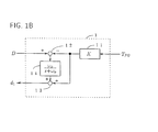
- element 150 is a motor drive circuit for supplying the motor 100 with a drive current l a according to the drive signal D;
- element 1 is a disturbance torque observer for calculating a estimated disturbance torque signal d 1 ;
- element 10 is a torque correcting unit for correcting the control signal c according to the estimated disturbance torque d 1 and for outputting the result as the drive signal D.
- the first embodiment of this invention shown in FIG. 1A operates as follows: A disturbance torque Td is applied to the motor 100.
- the period detector 120 detects the period of the frequency signal FG generated by the frequency generator 110.
- the comparator 130 subtracts the detected period signal T FG from a desired period T, (constant value) and outputs the result of the subtraction as the period error ⁇ T FG .
- the arithmetic unit 140 calculates the control signal c, which is, for example, calculated so as to be equal to (Kp + K i /s) ⁇ T FG , wherein Kp is a proportional gain, K i is an integral gain and s is a Laplacian.
- the torque correcting unit 10 adds the control signal c to the estimated disturbance signal d 1 outputted by the disturbance torque observer 1 and outputs the result of the addition as the drive signal D.
- the operation of the disturbance torque observer 1 in calculating the estimated disturbance signal will be explained later.
- the drive circuit 150 supplies the drive current l a to the motor 100 according to the drive signal D.
- the speed of the motor 100 is controlled so as to reduce the period error to zero. In other words, the speed of the motor 100 is kept fixed. If the estimated disturbance signal is zero, these processes are substantially same as those of the conventional motor control apparatus shown in FIG. 11.
- element 11 is a gain setting unit for setting the gain to a constant K
- element 12 is a first adder
- element 13 is a second adder
- element 14 is a first-order low-pass filter, whose transfer function is: ⁇ o /(s + ⁇ o ), wherein ⁇ o is a cut-off angular frequency.
- the constant K is represented as follows: wherein J represents the inertia of the motor 100, K t is a torque constant, K amp is the gain of the drive circuit 150, and Z is the number of the pulses per revolution generated by the frequency generator 110.
- the disturbance torque observer 1 shown in FIG. 1B acts as follows:
- the detected period T FG from the period detector 120 is multiplied by the constant K.
- the result of the multiplication is subtracted from the drive signal D by the first adder 12.
- the output of the first adder is supplied the low-pass filter 14.
- the second adder 13 adds the output of the low-pass filter 14 to the output of the multiplication and outputs the result of the addition as the estimated disturbance signal di .
- the estimated disturbance signal d 1 is added to the control signal c by the torque correcting unit 10.
- the influence of the disturbance torque T d is cancelled and a fluctuation in the speed of the motor 100 is eliminated.
- x(t) represents the time-domain function of the detected period and that y(t) represents the time-domain function of the angular speed of the motor 100.
- L represents a Laplace transform
- ⁇ represents the s-domain function of the speed of the motor 100.
- Eq. (9) means that the estimated disturbance signal d 1 is equal to the disturbance torque T d multiplied by the reciprocal of the torque constant K t , the reciprocal of the gain of the drive circuit 150 and the transfer function of the low-pass filter 14.
- the estimated disturbance signal d 1 consists of low- frequency components of the conversion signal of the disturbance torque T d in a dimension of the control signal c.
- the transfer function G(s) from the disturbance torque T d to the speed ⁇ of the motor 100 in FIG. 1A becomes as follows using Eq. (9): where G c (s) represents the transfer function from the disturbance torque T d to the speed ⁇ in FIG. 11, which is a conventional motor control apparatus.
- This term represents the transfer function of the first-order high-pass filter, whose cut-off angular frequency is ⁇ o .
- the disturbance torque observer 1 makes it possible to eliminate a fluctuation in the speed of the motor 100 due to a disturbance torque 7d , which has a frequency which is lower than ⁇ o /(2 ⁇ ).
- the disturbance torque observer it is not necessary for the disturbance torque observer to convert the detected period into the motor speed, because the disturbance torque observer can utilize the detected period T FG directly as its input signal.
- the disturbance torque observer according to this invention has a simpler configuration than a conventional disturbance torque observer, because this observer is constituted so as to convert the disturbance torque 7d into an electrical signal c directly without the determination of the actual disturbance torque 7d itself. Therefore, it can be easily applied to a motor control apparatus to keep the speed of the motor fixed with respect to the period of the frequency signal. As the result, fluctuations in the motor speed can be eliminated without making the hardware or a software program for the motor control complicated.
- element 2 is a disturbance torque observer according to the second embodiment. Since the other elements are same as those shown in FIG. 1A, a description thereof has been omitted.
- element 11 is a gain setting unit for setting a gain to a constant K
- element 12 is a first adder
- element 13 is a second adder
- element 14 is a first-order low-pass filter, whose transfer function is: ⁇ o /(s + ⁇ o ).
- the configuration of the disturbance torque observer 2 is the same as that of the disturbance torque observer 1 shown in FIG. 1 B.
- the disturbance torque observer 2 is different from the disturbance torque observer 1 in that it uses the period error AT FG in place of the detected period T FG .
- the disturbance torque observer 2 calculates the estimated disturbance signal d 2 according to the error signal ⁇ T FG and the drive signal D.
- the disturbance torque observer 2 shown in FIG. 2B operates as follows: The period error AT FG outputted by the comparator 130 is multiplied by the constant K. The result of the multiplication is added to the drive signal D by the first adder 12. The output of the first adder is supplied the low-pass filter 14. The second adder 13 subtracts the output of the low-pass filter 14 from the result of the multiplication and outputs the result of the subtraction as the estimated disturbance signal d 2 .
- the estimated disturbance signal d 2 is added to the control signal c by the torque correcting unit 10. By this torque correction, the influence of the disturbance torque 7d is cancelled and the fluctuation in the speed of the motor 100 is eliminated.
- w(t) represent the time-domain function of the period error. Namely, one can assume as follows: and the relationship between x(t) and w(t) is as follows:
- the second embodiment of this invention one can obtain the same effect as that of the first embodiment. Furthermore, since the magnitude of the period error ⁇ T FG is smaller than that of the detected period T FG , the dynamic range of the disturbance torque observer 2 can be narrower than that of the disturbance torque observer 1.
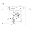
- the configuration of the third embodiment is same as that of the second one shown in FIG. 2A.
- the operations performed by the period detector 120, the comparator 130, the arithmetic unit 140, the correcting unit 10 and the disturbance torque observer 2 are realized by using a processor which operates according to a software program stored in memory.
- FIG. 3 shows a block diagram of the disturbance torque observer 2 modified for use with a software servo, namely in which the low-pass filter 14 is digitally emulated.
- element 41 is a gain setting unit for setting a gain to a constant ⁇ 1 ;
- element 45 is a gain setting unit for setting a gain to a constant a 2 ;
- elements 43 and 46 are delay units for effecting a delay of one sampling time T S , and
- elements 42 and 44 are adders.
- the transfer function Q 1 (z) of the low-pass filter 14 is given by the following equation: where constants ⁇ 1 and a 2 are as follows using the sampling time T s :
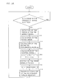
- FIG. 4A is a flowchart illustrating the operation sequence of the third embodiment
- FIG. 4B is a detailed flowchart illustrating the operation sequence of the disturbance torque observer 2 shown in FIG. 3.
- the block 50 determines whether or not the edge of the frequency signal FG has been inputted to the processor. If the edge has been inputted, the operation moves to the next block 51, and if not, the operation returns to the block 50. Namely, the operation of the block 50 is carried out repeatedly until the edge is inputted.
- the block 51 stores the time when the edge was inputted and calculates the detected period T FG from the difference between this input time and the last input time. This block 51 corresponds to the operation performed by the period detector 120 shown in FIG. 2A.
- the block 52 calculates the period error ⁇ T FG by subtracting the detected period T FG from the desired period T,. This block 52 corresponds to the operation performed by the comparator 130 shown in FIG. 2A.
- the block 53 calculates the estimated disturbance signal d 2 from both the period error AT FG and the previously stored memory data M i .
- This block 53 corresponds to the operation performed by the disturbance torque observer 2 shown in FIG. 3. The details of the operation of this block will be described later.
- the block 54 calculates the control signal c which is the result of servo compensation, for example, both proportional and integral compensation.
- This block 54 corresponds to the operation performed by the arithmetic unit 140 shown in FIG. 2A. Because how this compensation is realized using a software servo is well-known, the details thereof have been omitted.
- the block 55 calculates the drive signal D, which is obtained by adding the estimated disturbance signal d 2 to the control signal c.
- This block 55 corresponds to the operation performed by the correcting unit 140 shown in FIG. 2A.
- the block 56 stores the drive signal D in memory as the memory data M 1 which is used in the block 53 when the next edge of the frequency signal FG is inputted.
- This block 56 corresponds to the operation performed by the delay unit 46 shown in FIG. 3.
- the block 57 provide a D/A (digital to analog) converter with the drive signal D. After the block 57, the operation returns to the block 50.
- the above operations are carried out repeatedly while being synchronized with the frequency signal FG.
- the D/A converter provide the drive circuit 150 with a voltage according to the drive signal D.
- the drive circuit 150 supplies the drive current l a to the motor 100 according to this voltage. As the result, the speed of the motor 100 is controlled so as to reduce the period error to zero and is kept fixed.
- the block 53 consists of the blocks 530-537.
- the block 530 calculates the digital data a which is the period error AT FG multiplied by the constant K.
- This block 530 corresponds to the operation performed by the gain setting unit 11.
- the block 531 calculates the digital data b by adding the above mentioned memory data M 1 to the digital data a.
- This block 531 corresponds to the operation performed by the first adder 12.
- the block 532 calculates the digital data p which is the memory data M 2 multiplied by the constant a 2 , where M 2 has been previously stored in memory.
- This block 532 corresponds to the operation performed by the gain setting unit 41.
- the block 533 calculates the digital data q by adding the digital data b to the digital data p.
- This block 533 corresponds to the operation performed by the adder 42.
- the block 534 calculates the digital data V1 by adding the above mentioned memory data M 2 to the digital data q.
- This block 534 corresponds to the operation performed by the adder 44.
- the block 535 stores the digital data V 1 in memory as the memory data M 2 for the blocks 532 and 534 when the next edge of the frequency signal is inputted.
- This block 535 corresponds to the operation performed by the delay unit 43 shown in FIG. 3.
- the block 536 calculates the digital data v 2 which is the digital data V1 multiplied by the constant a 2 .
- This block 536 corresponds to the operation performed by the gain setting unit 45.
- the block 537 calculates the estimated disturbance signal d 2 by subtracting the digital data a from the digital data v 2 .
- This block 537 corresponds to the operation performed by the second adder 13.
- the disturbance torque observer 2 shown in FIG. 3 is configured so as to act in the same manner as that shown in FIG. 2A.
- a fourth embodiment of this invention which is a modification of the third embodiment so as to shorten the time lag due to the operation of the processor, is described below.
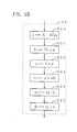
- FIG. 5A is a flowchart illustrating the operation sequence of the fourth embodiment
- FIG. 5B and FIG. 5C are detailed flowcharts illustrating the operation sequence of the disturbance torque observer 2 shown in FIG. 3. Since the configuration of the fourth embodiment is same as that of the third embodiment, a description of the configuration of the fourth embodiment has been omitted and only the operation sequence according to the fourth embodiment is described below.
- the block 58 calculates the estimated disturbance signal d 2 from both the period error fj. TFG and the previously stored memory data M i .
- the block 59 carries out the operation performed by the disturbance torque observer 2 which isn't carried out by the block 58.
- the block 58 consists of six blocks as shown in FIG. 5B. Though each block is as mentioned above, the order of the operation sequence is different.
- the block 530 calculates the digital data a which is the period error ⁇ T FG multiplied by the constant K. This block 530 corresponds to the operation performed by the gain setting unit 11.
- the block 531 calculates the digital data b by adding the above mentioned memory data M 1 to the digital data a. This block 531 corresponds to the operation performed by the first adder 12.
- the block 533 calculates the digital data q by adding the digital data b to the digital data p which has been previously calculated. This block 533 corresponds to the operation performed by the adder 42.
- the block 534 calculates the digital data V1 by adding the memory data M 2 , which has been previously stored in mentory, to the digital data q. This block 534 corresponds to the operation performed by the adder 44.
- the block 536 calculates the digital data v 2 which is the digital data V1 multiplied by the constant a 2 . This block 536 corresponds to the operation performed by the gain setting unit 45.
- the block 537 calculates the estimated disturbance signal d 2 by subtracting the digital data a from the digital data v 2 . This block 537 corresponds to the operation performed by the second adder 13.
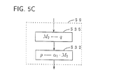
- the block 59 consists of two blocks, namely the blocks 535 and 532.
- the block 535 stores the digital data q, which is calculated at the block 533, in the memory as the memory data M 2 .
- This memory data M 2 is used at the block 534 when the next edge of the frequency signal FG is inputted.
- This block 535 corresponds to the operation performed by the delay unit 43 shown in FIG. 3.
- the block 532 calculates the digital data p by multiplying the memory data M 2 , which is stored in memory at the previous block 535, by the constant a 2 .
- This block 532 corresponds to the operation performed by the gain setting unit 41.
- this time lag is approximately equal to the time period from the time when the edge of the frequency signal is inputted until the time when the drive signal D is outputted to the D/A converter.
- the operation sequence according to the third embodiment shown in FIG. 4A needs three multiplications, which are carried out at the blocks 530, 532 and 536, before the drive signal D is outputted. Among these multiplications, the multiplication at the block 532 can be carried out after the output of the drive signal D.
- the operation sequence according to the fourth embodiment is so modified.
- the inferiority of the servo performance due to the time lag is reduced, because the time lag becomes shorter. It goes without saying that the same effect that is obtained by the third embodiment can be obtained with respect to the suppression of the influence of the disturbance torque.
- a fifth embodiment of this invention which is another modification of the second embodiment for use with a software servo, is described below.
- the configuration of the fifth embodiment is same as that of the second embodiment shown in FIG. 2A.
- the operations performed by the period detector 120, the comparator 130, the arithmetic unit 140, the correcting unit 10 and the disturbance torque observer 2 are realized by using a processor which operates according to a software program stored in memory.
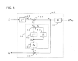
- FIG. 6 is another block diagram of the disturbance torque observer 2 modified for use with a software servo, namely, in which the low-pass filter 14 is digitally emulated.
- element 61 is a gain setting unit for setting a gain to a constant ⁇ 1 ;
- element 64 is a gain setting unit for setting a gain to a constant ⁇ 2;
- element 63 is a delay unit for providing a delay of one sampling time TS.
- the transfer function Q 2 (z) of the low-pass filter 14 is given by the following equation: where constants ⁇ 1 and ⁇ 2 are as follows using the sampling time T S :
- FIG. 7A is a flowchart illustrating the operation sequence of the fifth embodiment.
- FIG. 7B and FIG. 7C are detailed flowcharts illustrating the operation sequence of the disturbance torque observer 2 shown in FIG. 6.
- FIG. 7A only the block 70 and the block 71 corresponding to the operation performed by the disturbance torque observer 2 shown in FIG. 6 are different front the blocks in FIG. 4A. Therefore, only these blocks are described below.
- the block 70 calculates the estimated disturbance signal d 2 front both the period error ⁇ T FG and the previously stored memory data M i .
- the block 71 carries out the operation performed by the disturbance torque observer 2 shown in FIG. 6 which isn't carried out at the block 70.
- the block 70 consists of two blocks, namely the blocks 700-701, as shown in FIG. 7B. Firstly, the block 700 calculates the digital data a by multiplying the period error ⁇ T FG by the constant K. This block 700 corresponds to the operation performed by the gain setting unit 11. Then, the block 701 calculates the estimated disturbance signal d 2 by subtracting the digital data a from the previously calculated digital data v 3 . This block 701 corresponds to the operation performed by the second adder 13.
- the block 71 consists of four blocks, namely the blocks 710-713, as shown in FIG. 7C.
- the block 710 calculates the digital data b by adding the memory data M i , which is previously stored in memory, to the digital data a.
- This block 710 corresponds to the operation performed by the first adder 12.
- the block 711 calculates the digital data p i by multiplying the memory data M 3 , which has been previously stored in the memory, by the constant ⁇ 1 .
- This block 711 corresponds to the operation performed by the gain setting unit 61.
- the block 712 calculates the digital data v 3 by multiplying the above mentioned memory data M 3 by the constant ⁇ 2 .
- This block 712 corresponds to the operation performed by the gain setting unit 64 and this digital data v 3 is utilized by the block 701 when the next edge of the frequency signal FG is inputted.
- the block 713 adds the digital data b, which has been already calculated at the block 710, to the digital data p i and stores the result of this addition in memory as the memory data M 3 .
- This memory data M 3 is used at the blocks 711-712 when the next edge of the frequency signal FG is inputted.
- This block 713 corresponds to the operation performed by the delay unit 63 shown in FIG. 6.
- the process of calculating the estimated disturbance signal d 2 becomes much simpler in comparison with that of the fourth embodiment. Although two multiplications are necessary prior to the outputting of the estimated disturbance signal d 2 in the operation sequence of the fourth embodiment, only one multiplication is needed in the operation sequence of this fifth embodiment.
- the inferior servo performance caused by the time lag is reduced.
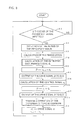
- FIG. 8 is a flowchart illustrating the operation sequence of the sixth embodiment.
- the configuration of the sixth embodiment is same as that of the fifth embodiment.
- the blocks 80-81 are added to the operation sequence shown in FIG. 7A. and the other blocks are same as the blocks shown in FIG. 7A, FIG. 7B and FIG. 7C.
- the estimated disturbance signal d 2 is calculated through the blocks 50, 51, 52 and 70. The operation of these blocks has been already described.
- the first torque correction is carried out by adding the estimated disturbance signal d 2 to the control signal c, which has been previously calculated and called Cn - 1 below, and the result is outputted as the drive signal D.
- This block 80 corresponds to the operation performed by the torque correcting unit 10.
- the drive signal D is provided to the D/A converter. The D/A converter immediately supplies the drive circuit 150 with a voltage according to this drive signal D.
- the control signal c which is called c " below, is calculated.
- the second torque correction is carried out by adding the estimated disturbance signal d 2 to the control signal c " and the result is outputted as the drive signal D.
- This block 55 also corresponds to the torque correcting unit 10.
- the drive signal D calculated at the block 55 and the control signal c " calculated at the block 54 are respectively stored in memory as the memory data M 1 and the control signal C n - 1 .
- the drive signal D calculated at the block 55 is again provided to the D/A converter.
- the D/A converter immediately supplies the drive circuit 150 with a voltage according to this drive signal D. After the operation of the block 57, the operation returns to the block 50.
- the above operations are carried out repeatedly while being synchronized with the frequency signal FG.
- the drive circuit 150 supplies the drive current l a to the motor 100 according to the voltage input thereto. As the result, the speed of the motor 100 is controlled so as to reduce the period error to zero and is kept fixed.
- the operation sequence of the sixth embodiment of this invention is contrived so as not cause this time lag.
- the first torque correction is carried out at the block 80 immediately after the calculation of the estimated disturbance d 2 and the drive signal D is outputted.
- the second torque correction is carried out at the block 55 after the calculation of the control signal c " and the drive signal D is outputted again.
- a seventh embodiment of this invention which is a modification of the third embodiment, is described below.
- the servo performance when the motor is started up is also considered.
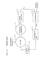
- FIG. 9 shows the seventh embodiment of this invention.
- the judging unit 20 is added to the configuration shown in FIG. 2A.
- the judging unit 20 judges the magnitude of the period error AT FG and provide the disturbance torque observer 2 with the reset signal Re according to the result of the judgement.
- the disturbance torque observer 2 shown in FIG. 9 has the same configuration as that shown in FIG. 3, and the other elements are same as those shown in FIG. 2A.
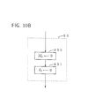
- FIG. 10A is a flowchart illustrating the operation sequence of the seventh embodiment
- FIG. 10B is a flowchart illustrating the operation sequence for initializing the process of the disturbance torque observer 2 shown in FIG. 3.
- the voltage corresponding to the start-up torque required for starting up the motor 100 is outputted by the processor through the D/A converter.
- the voltage is provided to the drive circuit 150.
- the drive circuit 150 supplies the motor 100 with the drive current l a according to said voltage, and then the motor 100 starts rotating.
- the frequency generator 110 After the motor 100 is started up, the frequency generator 110 generates the frequency signal FG whose frequency is in proportion to the speed of the motor.
- the frequency signal FG is inputted to the processor and the operation sequence shown in FIG. 10A is carried out.
- the disturbance torque observer 2 cannot estimate the disturbance torque accurately, because the differential equation between the time-domain function y(t) of the speed ⁇ of the motor 100 and the time-domain function x(t) of the period T FG of the frequency signal FG, which is given by Eq. (5), isn't satisfied. For this reason, at the block 93, the process of the disturbance torque observer 2 is initialized.
- the block 93 consists of two blocks 930 and 931.
- the memory data M i which has been previously stored in memory, is set to zero.
- the estimated disturbance signal d 2 is also set to zero.
- the torque correction isn't carried out substantially, when the period error AT FG is beyond the fixed bounds. Therefore, according to this embodiment, the motor is started up smoothly, because the torque correction in accordance with an inaccurate estimated disturbance signal can be prevented. After the motor has been started up and its speed reaches a static condition the effect of the disturbance suppression, which is represented by Eq. (10), can be obtained.
- the period error ⁇ T FG is inputted to the disturbance torque observer 2.
- the detected period T FG which is outputted by the period detector 120, can be used as a substitute for the period error AT FG -
- any signal can be used so long as it substantially corresponds to the period of the frequency signal FG.
- a detected velocity signal of the motor 100 or an error signal in speed can be used as the input signal of the disturbance torque observer 2 instead of the period error ⁇ T FC .
Landscapes
- Engineering & Computer Science (AREA)
- Power Engineering (AREA)
- Control Of Electric Motors In General (AREA)
Applications Claiming Priority (6)
| Application Number | Priority Date | Filing Date | Title |
|---|---|---|---|
| JP31306692A JP3227838B2 (ja) | 1992-11-24 | 1992-11-24 | モータ制御装置 |
| JP313066/92 | 1992-11-24 | ||
| JP5012288A JPH06225567A (ja) | 1993-01-28 | 1993-01-28 | モータ制御装置 |
| JP12288/93 | 1993-01-28 | ||
| JP12289/93 | 1993-01-28 | ||
| JP5012289A JPH06233573A (ja) | 1993-01-28 | 1993-01-28 | モータ制御装置 |
Publications (3)
| Publication Number | Publication Date |
|---|---|
| EP0599190A2 true EP0599190A2 (fr) | 1994-06-01 |
| EP0599190A3 EP0599190A3 (fr) | 1995-11-22 |
| EP0599190B1 EP0599190B1 (fr) | 1997-04-16 |
Family
ID=27279780
Family Applications (1)
| Application Number | Title | Priority Date | Filing Date |
|---|---|---|---|
| EP93118534A Expired - Lifetime EP0599190B1 (fr) | 1992-11-24 | 1993-11-18 | Dispositif de régulation de la vitesse de moteurs |
Country Status (5)
| Country | Link |
|---|---|
| US (1) | US5467004A (fr) |
| EP (1) | EP0599190B1 (fr) |
| KR (1) | KR0133354B1 (fr) |
| CN (1) | CN1038172C (fr) |
| DE (1) | DE69309857T2 (fr) |
Cited By (4)
| Publication number | Priority date | Publication date | Assignee | Title |
|---|---|---|---|---|
| EP0689282A1 (fr) * | 1994-06-23 | 1995-12-27 | SANYO ELECTRIC Co., Ltd. | Système servo à moteur |
| EP0709952A1 (fr) * | 1994-10-25 | 1996-05-01 | Matsushita Electric Industrial Co., Ltd. | Appareil de commande de vitesse de moteur |
| EP0680138A3 (fr) * | 1994-04-28 | 1997-07-02 | Matsushita Electric Industrial Co Ltd | Appareil de commande de la vitesse d'un moteur. |
| EP3968513A4 (fr) * | 2019-05-09 | 2022-06-29 | Panasonic Intellectual Property Management Co., Ltd. | Système de commande de moteur, procédé de commande de moteur et programme |
Families Citing this family (20)
| Publication number | Priority date | Publication date | Assignee | Title |
|---|---|---|---|---|
| JPH07110717A (ja) * | 1993-08-19 | 1995-04-25 | Fanuc Ltd | モータの制御方式 |
| JP3288184B2 (ja) * | 1994-10-05 | 2002-06-04 | 三菱電機株式会社 | 電動機の制御装置 |
| JP3481004B2 (ja) * | 1995-02-02 | 2003-12-22 | ファナック株式会社 | 外乱オブザーバを使用したバックラッシュ補正方法 |
| JP3655378B2 (ja) * | 1995-11-28 | 2005-06-02 | ファナック株式会社 | サーボモータの外乱負荷推定方法 |
| US6121747A (en) * | 1997-09-02 | 2000-09-19 | Servologic Ltd. | Electric motor controller |
| FI112734B (fi) * | 1998-05-20 | 2003-12-31 | Abb Oy | Menetelmä ja sovitelma kuormitusmuutosten adaptiiviseksi kompensoinniksi |
| US7177106B2 (en) * | 2001-02-26 | 2007-02-13 | Matsushita Electric Industrial Co., Ltd. | Disk storage apparatus |
| US7030588B2 (en) * | 2002-03-20 | 2006-04-18 | Kabushiki Kaisha Yaskawa Denki | Control constant adjusting apparatus |
| JP4007197B2 (ja) * | 2003-01-16 | 2007-11-14 | トヨタ自動車株式会社 | モータ制御装置 |
| CN100424981C (zh) * | 2004-03-26 | 2008-10-08 | 株式会社安川电机 | 电机控制装置 |
| US7560890B2 (en) * | 2004-07-29 | 2009-07-14 | Mitsubishi Denki Kabushiki Kaisha | Position controller and controlling method therefor |
| CN101420200B (zh) * | 2007-10-26 | 2012-07-25 | 浙江安露清洗机有限公司 | 通用发电机速度控制器 |
| JP4816754B2 (ja) * | 2009-03-31 | 2011-11-16 | ブラザー工業株式会社 | モータ制御装置及び画像形成システム |
| US8164293B2 (en) | 2009-09-08 | 2012-04-24 | Hoffman Enclosures, Inc. | Method of controlling a motor |
| US8183810B2 (en) | 2009-09-08 | 2012-05-22 | Hoffman Enclosures, Inc. | Method of operating a motor |
| US8297369B2 (en) | 2009-09-08 | 2012-10-30 | Sta-Rite Industries, Llc | Fire-extinguishing system with servo motor-driven foam pump |
| CN103901904B (zh) * | 2012-12-28 | 2016-09-28 | 上海微电子装备有限公司 | 一种电机位置干扰力校准方法 |
| CN109328175B (zh) * | 2016-06-30 | 2021-01-05 | 三菱电机株式会社 | 电梯的控制装置 |
| CN109309461B (zh) * | 2017-07-28 | 2020-09-18 | 上海三菱电梯有限公司 | 电梯启动控制装置 |
| CN109305612B (zh) * | 2017-07-28 | 2020-09-18 | 上海三菱电梯有限公司 | 电梯启动控制装置 |
Family Cites Families (6)
| Publication number | Priority date | Publication date | Assignee | Title |
|---|---|---|---|---|
| US4143311A (en) * | 1976-09-30 | 1979-03-06 | Xerox Corporation | Hysteresis synchronous motor rate servo system |
| US4360767A (en) * | 1979-02-09 | 1982-11-23 | Matsushita Electric Industrial Co., Ltd. | Motor speed control apparatus |
| JPS62196002A (ja) * | 1986-02-21 | 1987-08-29 | Hitachi Ltd | チヨツパ制御方式 |
| US4878165A (en) * | 1986-03-31 | 1989-10-31 | Matsushita Electric Industrial Co., Ltd. | Control system with improved robustness to disturbances |
| US5298841A (en) * | 1990-04-18 | 1994-03-29 | Hitachi, Ltd. | Apparatus for controlling the speed of a moving object |
| JP3021606B2 (ja) * | 1990-10-31 | 2000-03-15 | ソニー株式会社 | キャプスタンサーボ装置 |
-
1993
- 1993-11-17 US US08/153,102 patent/US5467004A/en not_active Expired - Fee Related
- 1993-11-18 DE DE69309857T patent/DE69309857T2/de not_active Expired - Fee Related
- 1993-11-18 EP EP93118534A patent/EP0599190B1/fr not_active Expired - Lifetime
- 1993-11-23 KR KR1019930024979A patent/KR0133354B1/ko not_active Expired - Fee Related
- 1993-11-24 CN CN93121407A patent/CN1038172C/zh not_active Expired - Fee Related
Cited By (8)
| Publication number | Priority date | Publication date | Assignee | Title |
|---|---|---|---|---|
| EP0680138A3 (fr) * | 1994-04-28 | 1997-07-02 | Matsushita Electric Industrial Co Ltd | Appareil de commande de la vitesse d'un moteur. |
| US5710500A (en) * | 1994-04-28 | 1998-01-20 | Matsushita Electric Industrial Co., Ltd. | Motor speed control apparatus using phase-advance based estimated disturbance signal |
| EP0689282A1 (fr) * | 1994-06-23 | 1995-12-27 | SANYO ELECTRIC Co., Ltd. | Système servo à moteur |
| US5698960A (en) * | 1994-06-23 | 1997-12-16 | Sanyo Electric Co., Ltd. | Motor servo system |
| EP0709952A1 (fr) * | 1994-10-25 | 1996-05-01 | Matsushita Electric Industrial Co., Ltd. | Appareil de commande de vitesse de moteur |
| US5737483A (en) * | 1994-10-25 | 1998-04-07 | Matsushita Electric Industrial Co., Ltd. | Motor speed control apparatus for motors |
| EP3968513A4 (fr) * | 2019-05-09 | 2022-06-29 | Panasonic Intellectual Property Management Co., Ltd. | Système de commande de moteur, procédé de commande de moteur et programme |
| US11791751B2 (en) | 2019-05-09 | 2023-10-17 | Panasonic Intellectual Property Management Co., Ltd. | Motor control system, motor control method, and program |
Also Published As
| Publication number | Publication date |
|---|---|
| CN1038172C (zh) | 1998-04-22 |
| EP0599190A3 (fr) | 1995-11-22 |
| KR0133354B1 (ko) | 1998-04-14 |
| EP0599190B1 (fr) | 1997-04-16 |
| CN1101179A (zh) | 1995-04-05 |
| US5467004A (en) | 1995-11-14 |
| DE69309857T2 (de) | 1997-08-28 |
| DE69309857D1 (de) | 1997-05-22 |
Similar Documents
| Publication | Publication Date | Title |
|---|---|---|
| EP0599190A2 (fr) | Dispositif de régulation de la vitesse de moteurs | |
| US5773938A (en) | Apparatus for controlling speed of a rotary motor | |
| US5433541A (en) | Control device for controlling movement of a printing head carriage and control method for controlling the same | |
| KR100223393B1 (ko) | 모터속도제어장치 | |
| EP0805383B1 (fr) | Dispositif de regulation de vitesse d'un moteur rotatif | |
| JP3892823B2 (ja) | モータの速度制御装置 | |
| JP3243414B2 (ja) | 回転モータの速度制御方法及びその装置 | |
| JP3203989B2 (ja) | モータの速度制御装置 | |
| JPH10155292A (ja) | 2慣性系制御回路 | |
| KR0129596B1 (ko) | 모터용 속도 제어시스템에 적용된 속도추정 오브저버 | |
| US5392378A (en) | Speed controlling system and a predictor | |
| JP2959270B2 (ja) | 外乱推定補償器 | |
| JP2914725B2 (ja) | デジタル櫛形フィルタ | |
| JP3227838B2 (ja) | モータ制御装置 | |
| JP2914726B2 (ja) | 帰還型ディジタルくし形フィルタ | |
| JPH07177777A (ja) | モータ制御装置 | |
| JP2846504B2 (ja) | モータ制御装置 | |
| JPH06225567A (ja) | モータ制御装置 | |
| JP2850531B2 (ja) | サーボ補償器 | |
| JPH07177778A (ja) | モータ制御装置 | |
| JP2553591B2 (ja) | モータの回転速度制御装置 | |
| JPH01117676A (ja) | 回転制御装置 | |
| JP3304669B2 (ja) | 制御補償器 | |
| JPH09163780A (ja) | モータ速度制御装置 | |
| JPH11206166A (ja) | モータの速度制御装置 |
Legal Events
| Date | Code | Title | Description |
|---|---|---|---|
| PUAI | Public reference made under article 153(3) epc to a published international application that has entered the european phase |
Free format text: ORIGINAL CODE: 0009012 |
|
| AK | Designated contracting states |
Kind code of ref document: A2 Designated state(s): DE FR GB NL |
|
| 17P | Request for examination filed |
Effective date: 19941118 |
|
| PUAL | Search report despatched |
Free format text: ORIGINAL CODE: 0009013 |
|
| AK | Designated contracting states |
Kind code of ref document: A3 Designated state(s): DE FR GB NL |
|
| GRAG | Despatch of communication of intention to grant |
Free format text: ORIGINAL CODE: EPIDOS AGRA |
|
| 17Q | First examination report despatched |
Effective date: 19960719 |
|
| GRAH | Despatch of communication of intention to grant a patent |
Free format text: ORIGINAL CODE: EPIDOS IGRA |
|
| GRAH | Despatch of communication of intention to grant a patent |
Free format text: ORIGINAL CODE: EPIDOS IGRA |
|
| GRAA | (expected) grant |
Free format text: ORIGINAL CODE: 0009210 |
|
| AK | Designated contracting states |
Kind code of ref document: B1 Designated state(s): DE FR GB NL |
|
| REF | Corresponds to: |
Ref document number: 69309857 Country of ref document: DE Date of ref document: 19970522 |
|
| ET | Fr: translation filed | ||
| PLBE | No opposition filed within time limit |
Free format text: ORIGINAL CODE: 0009261 |
|
| STAA | Information on the status of an ep patent application or granted ep patent |
Free format text: STATUS: NO OPPOSITION FILED WITHIN TIME LIMIT |
|
| 26N | No opposition filed | ||
| REG | Reference to a national code |
Ref country code: GB Ref legal event code: IF02 |
|
| PGFP | Annual fee paid to national office [announced via postgrant information from national office to epo] |
Ref country code: FR Payment date: 20051108 Year of fee payment: 13 |
|
| PGFP | Annual fee paid to national office [announced via postgrant information from national office to epo] |
Ref country code: DE Payment date: 20051110 Year of fee payment: 13 |
|
| PGFP | Annual fee paid to national office [announced via postgrant information from national office to epo] |
Ref country code: NL Payment date: 20051115 Year of fee payment: 13 |
|
| PGFP | Annual fee paid to national office [announced via postgrant information from national office to epo] |
Ref country code: GB Payment date: 20051116 Year of fee payment: 13 |
|
| PG25 | Lapsed in a contracting state [announced via postgrant information from national office to epo] |
Ref country code: NL Free format text: LAPSE BECAUSE OF NON-PAYMENT OF DUE FEES Effective date: 20070601 Ref country code: DE Free format text: LAPSE BECAUSE OF NON-PAYMENT OF DUE FEES Effective date: 20070601 |
|
| GBPC | Gb: european patent ceased through non-payment of renewal fee |
Effective date: 20061118 |
|
| NLV4 | Nl: lapsed or anulled due to non-payment of the annual fee |
Effective date: 20070601 |
|
| REG | Reference to a national code |
Ref country code: FR Ref legal event code: ST Effective date: 20070731 |
|
| PG25 | Lapsed in a contracting state [announced via postgrant information from national office to epo] |
Ref country code: GB Free format text: LAPSE BECAUSE OF NON-PAYMENT OF DUE FEES Effective date: 20061118 |
|
| PG25 | Lapsed in a contracting state [announced via postgrant information from national office to epo] |
Ref country code: FR Free format text: LAPSE BECAUSE OF NON-PAYMENT OF DUE FEES Effective date: 20061130 |