EP0600676A2 - Cathéter orientable avec courbure et/ou rayon réglable et méthode - Google Patents
Cathéter orientable avec courbure et/ou rayon réglable et méthode Download PDFInfo
- Publication number
- EP0600676A2 EP0600676A2 EP93309452A EP93309452A EP0600676A2 EP 0600676 A2 EP0600676 A2 EP 0600676A2 EP 93309452 A EP93309452 A EP 93309452A EP 93309452 A EP93309452 A EP 93309452A EP 0600676 A2 EP0600676 A2 EP 0600676A2
- Authority
- EP
- European Patent Office
- Prior art keywords
- distal extremity
- catheter
- flexible elongate
- bend
- shaft
- Prior art date
- Legal status (The legal status is an assumption and is not a legal conclusion. Google has not performed a legal analysis and makes no representation as to the accuracy of the status listed.)
- Withdrawn
Links
Images


Classifications
-
- A—HUMAN NECESSITIES
- A61—MEDICAL OR VETERINARY SCIENCE; HYGIENE
- A61M—DEVICES FOR INTRODUCING MEDIA INTO, OR ONTO, THE BODY; DEVICES FOR TRANSDUCING BODY MEDIA OR FOR TAKING MEDIA FROM THE BODY; DEVICES FOR PRODUCING OR ENDING SLEEP OR STUPOR
- A61M25/00—Catheters; Hollow probes
- A61M25/01—Introducing, guiding, advancing, emplacing or holding catheters
- A61M25/0105—Steering means as part of the catheter or advancing means; Markers for positioning
- A61M25/0133—Tip steering devices
- A61M25/0158—Tip steering devices with magnetic or electrical means, e.g. by using piezo materials, electroactive polymers, magnetic materials or by heating of shape memory materials
-
- A—HUMAN NECESSITIES
- A61—MEDICAL OR VETERINARY SCIENCE; HYGIENE
- A61B—DIAGNOSIS; SURGERY; IDENTIFICATION
- A61B18/00—Surgical instruments, devices or methods for transferring non-mechanical forms of energy to or from the body
- A61B18/04—Surgical instruments, devices or methods for transferring non-mechanical forms of energy to or from the body by heating
- A61B18/12—Surgical instruments, devices or methods for transferring non-mechanical forms of energy to or from the body by heating by passing a current through the tissue to be heated, e.g. high-frequency current
- A61B18/14—Probes or electrodes therefor
- A61B18/1492—Probes or electrodes therefor having a flexible, catheter-like structure, e.g. for heart ablation
-
- A—HUMAN NECESSITIES
- A61—MEDICAL OR VETERINARY SCIENCE; HYGIENE
- A61M—DEVICES FOR INTRODUCING MEDIA INTO, OR ONTO, THE BODY; DEVICES FOR TRANSDUCING BODY MEDIA OR FOR TAKING MEDIA FROM THE BODY; DEVICES FOR PRODUCING OR ENDING SLEEP OR STUPOR
- A61M25/00—Catheters; Hollow probes
- A61M25/01—Introducing, guiding, advancing, emplacing or holding catheters
- A61M25/0105—Steering means as part of the catheter or advancing means; Markers for positioning
- A61M25/0133—Tip steering devices
- A61M25/0136—Handles therefor
-
- A—HUMAN NECESSITIES
- A61—MEDICAL OR VETERINARY SCIENCE; HYGIENE
- A61M—DEVICES FOR INTRODUCING MEDIA INTO, OR ONTO, THE BODY; DEVICES FOR TRANSDUCING BODY MEDIA OR FOR TAKING MEDIA FROM THE BODY; DEVICES FOR PRODUCING OR ENDING SLEEP OR STUPOR
- A61M25/00—Catheters; Hollow probes
- A61M25/01—Introducing, guiding, advancing, emplacing or holding catheters
- A61M25/0105—Steering means as part of the catheter or advancing means; Markers for positioning
- A61M25/0133—Tip steering devices
- A61M25/0144—Tip steering devices having flexible regions as a result of inner reinforcement means, e.g. struts or rods
-
- A—HUMAN NECESSITIES
- A61—MEDICAL OR VETERINARY SCIENCE; HYGIENE
- A61M—DEVICES FOR INTRODUCING MEDIA INTO, OR ONTO, THE BODY; DEVICES FOR TRANSDUCING BODY MEDIA OR FOR TAKING MEDIA FROM THE BODY; DEVICES FOR PRODUCING OR ENDING SLEEP OR STUPOR
- A61M25/00—Catheters; Hollow probes
- A61M25/01—Introducing, guiding, advancing, emplacing or holding catheters
- A61M25/0105—Steering means as part of the catheter or advancing means; Markers for positioning
- A61M25/0133—Tip steering devices
- A61M25/0147—Tip steering devices with movable mechanical means, e.g. pull wires
-
- A—HUMAN NECESSITIES
- A61—MEDICAL OR VETERINARY SCIENCE; HYGIENE
- A61B—DIAGNOSIS; SURGERY; IDENTIFICATION
- A61B17/00—Surgical instruments, devices or methods
- A61B17/00234—Surgical instruments, devices or methods for minimally invasive surgery
- A61B2017/00292—Surgical instruments, devices or methods for minimally invasive surgery mounted on or guided by flexible, e.g. catheter-like, means
- A61B2017/003—Steerable
-
- A—HUMAN NECESSITIES
- A61—MEDICAL OR VETERINARY SCIENCE; HYGIENE
- A61B—DIAGNOSIS; SURGERY; IDENTIFICATION
- A61B17/00—Surgical instruments, devices or methods
- A61B2017/00831—Material properties
- A61B2017/00867—Material properties shape memory effect
-
- A—HUMAN NECESSITIES
- A61—MEDICAL OR VETERINARY SCIENCE; HYGIENE
- A61B—DIAGNOSIS; SURGERY; IDENTIFICATION
- A61B18/00—Surgical instruments, devices or methods for transferring non-mechanical forms of energy to or from the body
- A61B2018/00315—Surgical instruments, devices or methods for transferring non-mechanical forms of energy to or from the body for treatment of particular body parts
- A61B2018/00345—Vascular system
- A61B2018/00351—Heart
-
- A—HUMAN NECESSITIES
- A61—MEDICAL OR VETERINARY SCIENCE; HYGIENE
- A61B—DIAGNOSIS; SURGERY; IDENTIFICATION
- A61B18/00—Surgical instruments, devices or methods for transferring non-mechanical forms of energy to or from the body
- A61B2018/00571—Surgical instruments, devices or methods for transferring non-mechanical forms of energy to or from the body for achieving a particular surgical effect
- A61B2018/00577—Ablation
-
- A—HUMAN NECESSITIES
- A61—MEDICAL OR VETERINARY SCIENCE; HYGIENE
- A61B—DIAGNOSIS; SURGERY; IDENTIFICATION
- A61B18/00—Surgical instruments, devices or methods for transferring non-mechanical forms of energy to or from the body
- A61B2018/0091—Handpieces of the surgical instrument or device
-
- A—HUMAN NECESSITIES
- A61—MEDICAL OR VETERINARY SCIENCE; HYGIENE
- A61B—DIAGNOSIS; SURGERY; IDENTIFICATION
- A61B18/00—Surgical instruments, devices or methods for transferring non-mechanical forms of energy to or from the body
- A61B2018/0091—Handpieces of the surgical instrument or device
- A61B2018/00916—Handpieces of the surgical instrument or device with means for switching or controlling the main function of the instrument or device
- A61B2018/0094—Types of switches or controllers
- A61B2018/00946—Types of switches or controllers slidable
-
- A—HUMAN NECESSITIES
- A61—MEDICAL OR VETERINARY SCIENCE; HYGIENE
- A61B—DIAGNOSIS; SURGERY; IDENTIFICATION
- A61B18/00—Surgical instruments, devices or methods for transferring non-mechanical forms of energy to or from the body
- A61B18/04—Surgical instruments, devices or methods for transferring non-mechanical forms of energy to or from the body by heating
- A61B18/12—Surgical instruments, devices or methods for transferring non-mechanical forms of energy to or from the body by heating by passing a current through the tissue to be heated, e.g. high-frequency current
- A61B18/1206—Generators therefor
- A61B2018/1246—Generators therefor characterised by the output polarity
- A61B2018/1253—Generators therefor characterised by the output polarity monopolar
-
- A—HUMAN NECESSITIES
- A61—MEDICAL OR VETERINARY SCIENCE; HYGIENE
- A61B—DIAGNOSIS; SURGERY; IDENTIFICATION
- A61B18/00—Surgical instruments, devices or methods for transferring non-mechanical forms of energy to or from the body
- A61B18/04—Surgical instruments, devices or methods for transferring non-mechanical forms of energy to or from the body by heating
- A61B18/12—Surgical instruments, devices or methods for transferring non-mechanical forms of energy to or from the body by heating by passing a current through the tissue to be heated, e.g. high-frequency current
- A61B18/14—Probes or electrodes therefor
- A61B2018/1467—Probes or electrodes therefor using more than two electrodes on a single probe
Definitions
- This invention relates to a steerable catheter with an adjustable bend location and or bend radius and method.
- the present invention provides a steerable catheter with an adjustable bend location and method.
- the present invention provides a catheter and method of the above character in which whipping is eliminated.
- the present invention provides a steerable catheter of the above character in which the distal extremity will rotate at a one-to-one relationship with respect to the proximal extremity of the catheter as the proximal extremity is rotated.
- the present invention provides a catheter and method of the above character which can be utilized with different types of bending mechanisms for the distal extremity of the catheter.
- the present invention provides a catheter and method of the above character in which the adjustment of the bend location can be readily accomplished.
- the present invention provides a catheter and method of the above character which is particularly adapted for use in mapping and ablation.
- the present invention provides a catheter and method of the above character in which the radius of the bend in the distal extremity can be changed while the catheter is in use.
- the present invention provides a catheter and method of the above character in which it is possible to adjust the length of the fixed portion of the distal extremity extending beyond the bend.
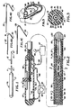
- FIG. 1 is a side elevational view of a steerable catheter incorporating the present invention.
- FIG. 2 is a side elevational view partially in cross-section showing one embodiment of a steerable catheter incorporating the present invention utilizing a shape-memory element.
- FIG. 3 is a cross-sectional view taken along the line 3-3 of FIG. 2.
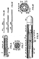
- FIGS. 4A, 4B and 4C show four examples of how an adjustable bend location in the steerable catheter makes possible bends in different locations in the distal extremity of the catheter.
- FIG. 5 is a diagrammatic illustration showing the manner in which the steerable catheter of the present invention can be utilized in a human heart to provide a different bend location to make it possible to reach difficult-to-reach portions of the wall forming a chamber in the heart.
- FIG. 6 is a partial cross-sectional view of another embodiment of a steerable catheter incorporating the present invention utilizing removable stiffening elements having weakened portions at different longitudinal positions of the stiffening elements.
- FIG. 7 is a cross-sectional view taken along the line 7-7 of FIG. 6.
- FIGS. 8A, 8B and 8C show stiffening elements having weakened regions in different longitudinal portions of the stiffening element.
- FIG. 9 is a partial cross-sectional view of the distal extremity of another embodiment of a steerable catheter incorporating the present invention utilizing telescoping stiffening elements.
- FIG. 10 is a cross-sectional view taken along the line 10-10 of FIG. 9.
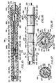
- FIG. 11 is a side elevational view of another embodiment of a steerable catheter incorporating the present invention.
- FIG. 12 is a cross-sectional view taken along line 12-12 of FIG. 11.
- FIG. 13 is a cross-sectional view taken along line 13-13 of FIG. 11.
- FIG. 14 is a cross-sectional view taken along line 14-14 of FIG. 11.
- FIG. 15 is an enlarged cross-sectional view of the handle of the steerable catheter shown in FIG. 11.
- FIG. 16 is a cross-sectional view of a portion of the handle shown in FIG. 15 with certain portions being shown in cross-section and rotated by 90° from that shown in FIG. 15.
- FIG. 17 is a cross-sectional view taken along line 17-17 of FIG. 16.
- FIG. 18 is a cross-sectional view taken along line 18-18 of FIG. 16.
- FIG. 19 is an enlarged cross-sectional view of the distal extremity of the catheter shown in FIG. 1.
- FIG. 20 is a cross-sectional view similar to FIG. 19 but rotated by 90°.
- FIGS. 21 and 22 are cross-sectional views of the distal extremity of the catheter shown in FIG. 1 showing in partially schematic form the manner in which different radius bends can be achieved by different positions of the bend location mandrel.
- FIG. 23 is an enlarged partial cross-sectional view of the distal extremity of the catheter encircled on FIG. 21 showing how bending is accomplished.
- the steerable catheter of the present invention consists of a flexible elongate tubular member having proximal and distal extremities.
- a plurality of circumferentially spaced-apart flexible elements are disposed in the distal extremity for causing bending of the distal extremity of the flexible elongate member.
- Movable means is disposed in the distal extremity of the flexible elongate member for selecting the location where bending in the distal extremity will take place and the radius of the bend.
- the steerable catheter 11 incorporating the present invention consists of a flexible elongate member 12 formed of a suitable material such as plastic which is provided with proximal and distal extremities 13 and 14.
- An ablation electrode 16 is carried by the distal extremity 14.
- a hand-held control mechanism 17 is mounted on the proximal extremity 13.
- the hand-held control mechanism 17 can be of various types. For example it can be of the type which can be utilized for actuating pull wires (not shown) extending longitudinally of the flexible elongate tubular member 12 which are well known to those skilled in the art and which can be utilized for bending the distal extremity of the flexible elongate tubular member 12.
- a steerable catheter 21 which consists of a flexible elongate tubular member 22 which is provided with proximal and distal extremities 23 and 24.
- a metal ablation electrode 26 is secured to the distal extremity 24.
- a hand-held control mechanism 27 is mounted on the proximal extremity 23 of the flexible elongate tubular member 22.
- the flexible elongate tubular member 22 is formed of a suitable material such as plastic and is provided with a plurality of circumferentially spaced-apart lumens 31-36, and a central lumen 37, all of which extend the length of the flexible elongate tubular member 22.
- a plurality of flexible elongate elements as for example three of such elements 41, 42 and 43, are disposed 120° apart and are provided in the lumens 31, 33 and 35.
- These flexible elongate elements 41, 42 and 43 are disposed in the distal extremity 24 of the flexible elongate tubular member 22 and are formed of a material which has a negative coefficient of expansion.
- the distal extremities of these flexible elongate members 41, 42 and 43 are connected to a common ground return 44 provided in the lumen 34.
- the three flexible elongate elements 41, 42 and 43 are also connected to conductors (not shown) which extend to the proximal extremity 23 of the flexible elongate member and with the ground return 44 connected into a cable 46 extending from the control mechanism 17 and are connected to a joystick control console 47 of the type described in co-pending application Serial No. 07/793,858, filed November 18, 1991, and which includes a joystick 48.
- the ablation electrode 26 is connected by a conductor 51 provided in the lumen 32 and extending into the control mechanism 17 and is connected to a suitable ablation power supply (not shown) conventionally used with such catheters.
- Bend adjustment means 56 is provided in the distal extremity 24 of the flexible elongate tubular member 22 and consists of a shape-memory element 57 formed of a suitable material such as Nitinol which has been provided with a memory which makes it assume a straight condition when it is heated such as by the application of electrical energy thereto.
- the shape-memory element 57 is provided with proximal and distal extremities 58 and 59.
- the proximal extremity 58 is connected by a joint 61 to a conductor 62 which extends into the control mechanism and is connected as hereinafter described.
- the distal extremity 59 is connected to a ground return conductor 44 by wire 63.
- the shape-memory element 57 can have a suitable diameter, as for example 5-20 mils.
- the bend adjustment means 56 also includes selective conductive bypass means 66 which is movable longitudinally along the length of the shape-memory element 57 to selectively inhibit current flow in a portion of the shape-memory element to permit bending of the shape-memory element 57 in that portion of the shape-memory element.
- the conductive bypass means 66 as shown in FIGS. 2 and 3 consists of an elongate cylindrical sleeve 67 formed of a suitable conducting material, as for example a silver mesh or braid, through which the shape-memory element 57 extends.
- Means is provided for adjusting the sleeve 67 longitudinally over the shape-memory element 57 and consists of a flexible tubular member 68 formed of a suitable insulating material such as plastic which is slidably mounted in the central lumen 37.
- the tubular member 68 is provided with a bore 69 therein extending the length thereof and in which the shape-memory element 57 is disposed. As can be seen particularly in FIG.
- the sleeve 67 has one end secured to the distal extremity of the flexible tubular member 68.
- the other end of the sleeve 67 is supported by another tubular member 71 of the same material and of the same diameter as the flexible tubular member 68 and is provided with a bore 72 through which the shape-memory element 57 extends.
- the sleeve 67 can be affixed to the tubular members 68 and 71 by suitable means such as an adhesive.
- the shape-memory element In order to ensure good conductivity between the silver braid or mesh sleeve 67, the shape-memory element should be cleaned with nitric and hydrochloric acids to remove any oxidation which may be present on the shape-memory element 57. This ensures that there is good electrical contact between the sleeve 67 and the shape-memory element so that minimal or no current flows in the portion of the shape-memory element 57 which is covered by the sleeve.
- Means is provided for controlling the movement of the flexible tubular member 68 and the sleeve 67 carried thereby from the control mechanism 27 and consists of a control member 76 which is secured to the proximal extremity of the tubular member 68.
- the control member 73 extends diametrically of the tubular member 68 through a longitudinally extending slot 77 provided in the sidewall of a cylindrical housing 78.
- the cylindrical housing 78 can be formed of a suitable material such as plastic or metal, and is sized in such a manner so that it is adapted to be held by the human hand. For example, it can have a diameter of approximately 1'' and a length of 5-6''.
- the conductor 62 is connected to a cable 82 which extends out of the housing 78 and is connected to a variable current power supply 83 which is provided with a control knob 84 to adjust the amount of current which is supplied to the sleeve 67.
- the variable current power supply 83 is also provided with another cable 86 which is connected to the ground return conductor 44.
- the sleeve 67 which is in close intimate contact with the shape-memory element 57, serves as a current bypass or bridge and causes the current to flow through the highly conductive silver mesh sleeve 67 to thereby bridge that portion of the shape-memory element 57 covered thereby so that it remains relatively flexible.
- the portion of the shape-memory element 57 underlying or within the sleeve 67 does not heat up and remains flexible and does not attempt to assume the straight condition of the remainder of the shape-memory element 57.
- FIG. 5 shows by providing different bend locations for the steerable catheter 11, it is possible to reach difficult-to-reach positions in the human heart.
- bends 94 and 96 in the catheter 11 Two different bends represented by the bends 94 and 96 in the catheter 11 are shown in which the bend 96 in contradistinction to the bend 94 makes it possible to reach a difficult-to-reach area of the wall 96 forming the chamber 97 of the human heart 98.
- FIGS. 6 and 7 Another embodiment of a steerable catheter incorporating the present invention is shown in the catheter 101 in FIGS. 6 and 7 which consists of a flexible elongate tubular member 102 formed of a suitable material such as plastic which is provided with a distal extremity 103 having a metal electrode 104 provided thereon.
- the flexible elongate member 102 is provided with a plurality of circumferentially spaced-apart lumens 106-111 and a central lumen 112.
- At least three pull wires 116, 117 and 118 are provided in the lumens 106, 108 and 109, which are connected into the distal extremity and which extend to the proximal end of the catheter 101 and are controlled by a conventional control mechanism (not shown) for causing bending of the distal extremity of the tubular elongate member 102.
- a conductor 119 is provided in the lumen 110 and is connected to the electrode 104.
- An elongate stiffening element 121 is slidably mounted in the central lumen 112. This stiffening element 121 is provided with a weakened longitudinal portion 121a of the stiffening element 121.
- This weakened portion 121a can be of a suitable length, as for example 1-5 cm. It can be seen that by utilizing such a stiffening element with such a weakened portion that the bending of the distal extremity 103 of the flexible elongate tubular member 102 will occur in the region of the weakened portion 121a.
- the stiffener element 121 can be interchanged with other stiffener elements, as for example stiffener elements 126, 127 and 128, as shown in FIGS. 8A, 8B and 8C, having weakened longitudinal portions 126a, 127a and 128a, respectively, at different longitudinal positions of the stiffener elements 126, 127 and 128. It can be seen that by selecting an appropriate stiffener element that the bend in the distal extremity of the flexible elongate member 102 can be made to occur in the desired location to provide different hinge points and also to provide different lengths of the stiffener element extending beyond the weakened region or hinge point.
- the catheter 131 consists of a flexible elongate member 132 formed of a suitable material such as plastic which is provided with a distal extremity 133 to which there is secured a tip electrode 134.
- the flexible elongate member 132 is provided with a plurality of circumferentially spaced-apart lumens 137-142 and a central lumen 143.
- At least three flexible elongate elements 146, 147 and 148 are disposed in the lumens 136, 138 and 139 and are formed of a material having a negative coefficient of expansion.
- the means for adjusting the bend location for the bending of the distal extremity 133 of the flexible elongate tubular member 132 is in the form of a telescoping assembly 151 formed of a suitable material such as stainless steel mounted in the central lumen of the distal extremity 133 of the catheter 131.
- the telescoping assembly 151 is movable between collapsed and extended positions and consists of an outer cylindrical member 152 which is secured within the distal extremity 133 by suitable means such as an adhesive.
- the outer cylindrical member is provided with a cylindrical bore 153 and a swaged end 154 providing an opening 155 in communication with the bore 153.
- An intermediate cylindrical member 156 is slidably mounted within the outer cylindrical member 152 and is provided with a flanged end 157 which is adapted to engage the swaged end 154 of the outer cylindrical member 152.
- the intermediate cylindrical member 156 is provided with a bore 158 and has a swaged end 159 forming a hole 161 extending therethrough.
- An inner cylindrical member 164 is provided which has a flange 166 which is adapted to travel in the bore 158. The inner cylindrical member 164 travels through the hole 161 and forms the distal extremity of an elongate flexible push-pull element 171 which extends to the proximal extremity (not shown) of the flexible elongate member 132.
- the flexible elongate element 171 can be formed of a suitable material such as stainless steel and can have a diameter of .012-.025''. It is provided a portion 171a of reduced diameter in close proximity to the inner cylindrical member 164 as shown in FIG. 9. By way of example, it can have a reduced diameter ranging from .006'' to .015''.
- the diameter of the flexible elongate element 171 should be of a diameter which is slightly greater than the size of the hole 161 for a purpose hereinafter described.
- the hinge point or bend location for the distal extremity 133 of the flexible elongate element 132 can be readily adjusted.
- the telescoping assembly 151 is in a collapsed position in which the push-pull element 171 has been pushed towards the distal extremity so that the distal extremity of the flexible elongate member 171 is in engagement with the proximal extremity of the intermediate cylindrical member 156 and the intermediate cylindrical member is disposed entirely within the outer cylindrical member 132.
- FIGS. 11-18 Another embodiment of the steerable catheter of the present invention having an adjustable bend location and/or radius is shown in FIGS. 11-18.
- the steerable catheter 201 consists of a flexible elongate member 202 having proximal and distal extremities 203 and 204.
- the proximal extremity 203 is secured to the handle 206 in the form of a control mechanism which is adapted to be grasped by the human hand.
- the flexible elongate member 202 is comprised of a first or inner shaft 211 and a second or outer shaft or sleeve 212 coaxially mounted on the first or inner shaft 211.
- the inner shaft 211 is in the form of a plastic extrusion which has been provided with a plurality of lumens extending therethrough.
- the inner shaft 211 is formed in two portions 211a and 211b. Both portions can be formed of the same plastic material, as for example PEBAX. However, in accordance with the present invention it is desirable to form the portion 211a of a softer material such as PEBAX having a 35 Shore D hardness and portion 211b of a harder material, as for example PEBAX having a 72 Shore D hardness.
- the portion 211b has a smaller outer diameter than the portion 211a to accommodate the second or outer shaft or sleeve 212 and to provide a smooth outer surface for the flexible elongate member 202.
- the two portions 211a and 211b can be readily joined together by a heat fusing process since both portions are formed of a PEBAX material.
- the two portions 211a and 211b of the first or inner shaft 211 are provided with a centrally disposed lumen 213 extending the length thereof and two additional lumens 214 and 216 aligned diametrically with lumen 213 and extending the length of the shaft 211.
- Two additional crescent or moon-shaped lumens 217 and 218 are provided in the shaft 211 on opposite sides of the diametrically aligned lumens 213, 214, and 216.
- the second or outer shaft or sleeve 212 is formed of a braided PEBAX material which has a braid embedded therein formed of a suitable material such as sixteen 40-gauge stainless steel strands having a braid angle of 60°.
- the second or outer shaft or sleeve 212 can have a suitable wall thickness, as for example .020'' with a corresponding reduction in the diameter of the portion 211b with respect to the portion 211a so that the outer surface of the sleeve is flush with the outer surface of the portion 211a.
- the braided sleeve or shaft 212 stops short of the distal extremity of the flexible elongate member 202 as indicated by the line 219 (see FIG. 19).
- the second or outer shaft or sleeve 212 serves to provide good torque transfer characteristics for the flexible elongate member 202.
- the portion 211a of the first inner shaft 211 has its distal extremity rotated or twisted through an angle, as for example from 270° to 250° and preferably approximately 360° through a length ranging from 10''-20'' and preferably a distance of about approximately 15''.
- FIG. 12 shows the initial starting position for the twist of the inner shaft portion 211a.
- FIG. 13 shows that the twist of the shaft portion 211a after it has been twisted by 180° and FIG.
- a tip electrode 221 is mounted on the distal extremity of the portion 211a and is formed of a suitable material such as platinum and is formed as a deep drawn cup with a rounded distal extremity and having an outer circumference which corresponds to the outer circumference of the portion 211a.
- the tip electrode 221 can have a suitable diameter, as for example .091'' and a have a suitable length, as for example 4 millimeters.
- the tip electrode 221 is provided with a longitudinal extending cavity 222. The distal extremity of the portion 211a is necked down and inserted into the cavity 222 and is retained therein by suitable means such as an adhesive (not shown).
- the tip electrode 221 is also secured to the distal extremity of the portion 211a by a member 223 in the form of a stainless steel hypotube having an outside diameter of approximately .025'' and an inside diameter of .019'' and having a length of approximately 1/4'' which is retained within the cavity 222 by a suitable means such as solder 224.
- the members 23 is secured to one end of a ribbon 226 by suitable means such as welding the ribbon 226 is formed of a suitable material such as a superelastic Nitinol which has a programmed memory of a straight shape. It can have suitable dimensions, as for example a width of .018'' and a thickness of .006'' and a length of approximately 3''.
- the ribbon 226 is slidably disposed in the central lumen 213.
- Means is provided for forming an electrical connection to the tip electrode 221 and consists of a insulated conductor 227 which has one end electrically connected to the tip 221 by the solder 224.
- the conductor 227 extends through the lumen 216 through the proximal extremity of the flexible elongate member 202.
- a plurality of conductive rings 228 formed of a suitable material such as platinum are mounted in insulated spaced-apart positions on the portion 211a of the shaft 211 and are connected to insulated conductors 229 which also extend to the proximal extremity of the flexible elongate member 202 through the lumen 216.
- Means is provided for causing bending of the distal extremity of the flexible elongate member 202 and consists of a pull wire 231 formed of a suitable material such as stainless steel having a diameter of .005''.
- the pull wire 231 is slidably mounted on the lumen 214 and is connected into the tip electrode 221 by having a beaded end 232 secured within the solder 224.
- the pull wire is coated with Teflon (not shown).
- a bend location mandrel 236 is slidably mounted in the central lumen 213. As shown, it can be circular in cross-section and can have a suitable diameter, as for example .017''. It is formed of a suitable material such as Nitinol. The proximal extremity of the bend location mandrel 236 is secured within the handle 206 as hereinafter described. The distal extremity of the mandrel 236 is secured by welding to an elongate ribbon 237 which is rectangular in cross-section and which is disposed in the central lumen 213. The ribbon 237 also is formed of a superelastic Nitinol which is rectangular in cross-section and can have suitable dimensions such as .019'' and a thickness of .008''.
- the ribbon 237 has a memory which causes it to return to a straight position when it is free to move.
- the ribbon 237 is mounted on the mandrel 236 so that it flexes in a direction which is at right angles to the width of the ribbon to permit bending of the portion 211a of the shaft 211 in the direction in which it can be pulled by the pull wire 231 but inhibiting flexing in a direction which is at right angles to the plane formed by the width of the ribbon.
- the ribbon 237 overlaps the ribbon 226 and is slidable longitudinally with respect to the ribbon 226 to adjust the bend location as hereinafter described.
- the handle 206 is in the form of an assembly which includes an elongate cylindrical body 241 formed of a suitable material such as plastic which is formed of a distal extremity 241a of a larger diameter and a portion 241b of a reduced diameter to form a shoulder 242.
- the body 241 is provided with an axially extending bore 243 extending therethrough which opens into a larger bore 244 provided in the distal extremity of the body 241.
- the portion 241b of reduced diameter is provided with an elongate slot 246 extending longitudinally thereof parallel to the longitudinal axis of the body 241.
- the portion 241a of larger diameter is also provided with first and second diametrically opposed open-ended slots 247 which are open at their distal extremities because they extend through the distal extremity of the body portion 241a.
- the slots 247 extend longitudinally of the body 241 and are parallel to the axis of the body 241. As shown in FIG. 16, the slots 247 are positioned so that at least one is aligned with the slot 246 in the portion 241b.
- the portion 241b of reduced diameter is also provided with spaced-apart inner recesses 249 on the outer cylindrical surface thereof.
- the body portion 241a is also provided with an annular recess 251 opening through the outer surface thereof.
- the handle 206 also includes a cylindrical nose piece 256 that has substantially the same outer diameter as the portion 241a of the body 241. It is provided with a rounded distal extremity 257.
- the nose piece 256 is provided with a large bore 258 in the proximal extremity of the same which opens into a smaller bore 259 which in turn opens into a slightly larger bore 261.
- the nose piece is provided with an annular recess 262 on the proximal extremity of its outer surface which is sized so that the proximal extremity of the nose piece 256 can be fit within the bore 244 provided in the body 241.
- the nose piece 256 is also provided with an annular recess 263 which is spaced distally from the recess 262.
- the handle 206 includes a handle member in the form of a circular knob 266 which is slidably mounted on the body 241 and the nose piece 256 when the nose piece is assembled into the body 241.
- the handle member 266 is in the form of an elongate sleeve 267 which has a bore 268 extending there through which is sized so that a slip fit is formed between the sleeve 267 and the body portion 241a and the nose piece 256.
- the handle member 266 is provided with an outwardly and circumferentially extending waist 269 which is provided with a rounded contour to facilitate grasping of the same by fingers of the hand holding the handle as for example the thumb and forefinger.
- Means is provided for securing the handle member 266 to the body portion 241a that consists of a cylindrical pin 271 formed of a suitable material such as stainless steel which extends through the waist 269 and extends through the slots 247 and 264 (see FIG. 18) which serves to limit the sliding movement of the handle member 266 to the length of the cooperating slots 247 and 264.
- the nose piece 256 is provided with first and second diametrically opposed slots 264 which open through the proximal extremity of the nose piece 256 and are aligned with the slots 247 in the body 241 so that when the nose piece 257 is assembled into the body 241, the slots 264 close the open ended slots 247.
- a pin 271 is disposed in counter-sunk bores 272 in the handle member which after the pin 271 is in place are filled with additional plastic 273 that is ground and polished so that the pin 271 is hidden from view of the human eye.
- the proximal extremity 203 of the flexible elongate member 202 is disposed in the bore 259 in the nose piece 256 is retained therein by suitable means such as an adhesive (not shown).
- a strain relief sleeve 276 formed of a suitable material such as plastic is mounted in the bore 261 and is retained therein by suitable means such as an adhesive (not shown) and extends over the proximal extremity of the flexible elongate member 202 (see FIG. 1).
- the bend location mandrel 236 extends from the proximal extremity of the flexible elongate member 202 and passes through a hole 281 provided in the pin 271 (see FIG. 18).
- the pull wire 231 also extends from the proximal extremity of the flexible elongate member 202 into the handle 206 and extends through a hole 282 offset from the hole 281 (see FIG. 18).
- the handle 206 also consists of the sleeve 286 which is provided with a portion 286a of a larger diameter handle and a portion 286b of a smaller diameter to form a shoulder 287.
- the portion 286a of larger diameter is provided with a plurality of circumferentially spaced apart longitudinally extending recesses 288 which are adapted to be grasped by the fingers of the hand holding the handle 206.
- the portion 286b is provided with a helically extending slot 291 which has its ends coterminus with the ends of the slot 246 in the portion 286b when the sleeve 286 is positioned over the portion 241b as shown in FIGS. 15 and 16.
- O-rings 292 provided in the annular recesses 248 and 249 and serve to provide a slight frictional engagement between the sleeve 286 and the body 241 to slightly inhibit the rotation of the sleeve 286 with respect to the body 241.
- the o-ring also prevents a fluid from entering the handle 206.
- An O-ring 273 is provided in the recess 263 which serves to provide a slight frictional engagement to retain the handle member 266 in a desired position longitudinally of the body 241 while still permitting relatively free movement of the handle member 266 relative to the body 241.
- the bend location mandrel 236 extends through the bore 243 of the body 241.
- the bend location mandrel 236 is formed of a suitable material such as .018'' Nitinol wire. It extends through a bore 294 provided in a block 296 formed of a suitable material such as plastic.
- the bore 294 opens into a larger bore 297 in the block 296 which opens through the distal extremity of the block.
- a sleeve 301 formed of a suitable material such as stainless steel hypotube having an inside diameter of .020'' and outside diameter of .032'' is secured to the proximal extremity of the bend location mandrel 236 by suitable means such as a TIG weld.
- the sleeve 301 is disposed in the bore 297 and retains the proximal extremity of the bend location mandrel 236 within the block 296 which as shown in FIG. 17 can have a rectangular cross-section.
- the sleeve 301 with the bend location mandrel 236 is retained within the block 296 by a dowel pin 302 which extends through a bore 303 transversely of the block 296 immediately behind the sleeve 301 to retain the sleeve 301 in the bore 297.
- the pin 302 also extends through the elongate slot 246 provided in the body 241 and into the helical slot 291 whereby as the sleeve 286 is rotated, the pin 302 will be caused to translate longitudinally of the handle 206 in the slot 246 to advance and retract the bend location mandrel 236 for a purpose hereinafter described.
- the handle 206 includes a cylindrical end piece 306 also formed of a suitable material such as plastic which is provided with a bore 307 opening through the distal extremity of the same.
- the bore 307 opens into a smaller bore 308 which in turn opens into a still smaller bore 309.
- the bore 309 opens into a larger bore 311.
- a plug 312 is seated within the bore 311 and is retained therein by suitable means such as an adhesive and carries a female electrical connector 313 of a conventional type which is recessed therein and which is provided with female recesses 314 formed of a conducting material which are connected to the conductors 226.
- a male connector 316 of a conventional type is adapted to seat within the female connector 313 (see FIG. 1) and is connected to a cable 317 that carries conductors 318 connected to conventional pins 319 that are adapted to be connected into conventional instrumentation for performing an ablation procedure as hereinafter described.
- the distal extremity 204 of the flexible elongate member 202 of the steerable catheter 201 can be introduced into the vessel of the patient, as for example a femoral artery in a conventional manner and introduced into the heart of the patient to a desired chamber of the heart by steering the distal extremity 204 of the flexible elongate member 202.
- the advancement of the distal extremity 204 can be observed fluoroscopically.
- large radius and small radius bends may be provided in the distal extremity 204 to make it possible to negotiate the vessel leading to the heart and to enter appropriate pathways in the heart to position the distal extremity 204 in an appropriate position in the chamber of the heart to perform an ablation.
- the cylindrical knob provided by the sleeve 286 is in a position so that the dowel pin 302 is in the proximal extremity of the helical slot 291 as shown in FIG. 1 so that the bend location mandrel 236 has been retracted to its extreme proximal position.
- the portion 211a of the shaft 211 will be relatively soft and floppy so that it can readily negotiate the femoral artery or other vessel into which it is being introduced.
- a bend can be placed in the distal extremity 204 when desired to negotiate a tortuosity in the vessel.
- the bend location mandrel 236 can be advanced by rotation of the sleeve 286 to cause the distal extremity of the mandrel 236 and the ribbon 237 carried thereby to be advanced distally to progressively overlap the ribbon 226 to cause the radius of the bend to be decreased. Extending the mandrel 236 with the ribbon 237 carried thereby to its distal-most extremity it can create a bend having a radius as small as 18 millimeters as shown in FIG. 22. Thus it can be seen that the radius of the bend can be increased in connection of the present embodiment without substantially changing the position of the bend. In the previous embodiments hereinbefore described, the bend location was changed but the radius was kept relatively constant.
- the catheter 201 has its distal extremity 204 arranged in such a manner that it only bends in a single direction because of the orientation of the ribbons 237 and 238 so that bending can only occur in a direction which is perpendicular to the width of the ribbons 226 and 237.
- the direction of bending will only occur in one direction because the pull wire 231 is disposed on one side of the ribbons 236 and 237 so that the ribbons will be bent in a direction toward the pull wires 231.
- the distal extremity can be torgued through an angle 360 degrees and more by utilizing the hand holding the handle to rotate the handle 206 the desired amount.
- the multilumen shaft 211 has been twisted through 360° as hereinbefore described within the braided or outer shaft or sleeve 212 so that the pull wire 231 shows no preferential orientation as it goes over the aortic arch. Because of the helix placed in the pull wire 231 by twisting of the portion 211a, the pull wire cannot assume a preferred orientation as it travels over the aortic arch. The approximately 15 centimeters of the flexible elongate member which is provided with this twist extends along the length of the portion of the catheter which typically would form the bend going over the aortic arch.
- the distal extremity 204 of the flexible elongate member 202 can be readily advanced into a chamber of the heart with bends in the heart being readily negotiated by placing the appropriate bend in the distal extremity and by selecting the appropriate radius for the bend. This can be readily accomplished by one hand of the physician holding the handle for rotation of the same and for creating bends of various radii by operation of the circular knob 266 and the sleeve knob 286.
- the distal extremity 204 can be readily advanced so that the tip electrode 221 and, if desired, the other spring electrodes 228 can be brought into engagement with the wall of the heart by appropriate operation of the handle 206.
- the bend in the distal extremity of the catheter can be removed by appropriate movement of the circular knob 266 and the sleeve knob 286 to permit removal of the steerable catheter 201 from the heart and then from the vessel of the patient.
- the steerable catheter 201 has several significant features. Because of the twisting of the catheter shaft 211, it is possible to avoid whipping of the catheter shaft and to prevent the pull wire from moving into a preferential position.
- the braided shaft or sleeve 212 serves two functions. It serves to prevent unwinding of the twist placed in the inner shaft 211. Also it makes it possible to transfer torque from one end of the outer shaft 212 to the other end of the shaft 212.
- a pair of Nitinol wires of a suitable diameter such as .010'' can be welded together along their length to provide a flat member which corresponds essentially to the ribbon 226.
- the mandrel 236 can have such a length so it overlaps the wires.
- a Nitinol ribbon can be soldered into the tip with the proximal extremity of the ribbon being connected to the pull wire 231.
- the strip would have a memory which would preferentially cause it to seek a straight shape.
- a Nitinol ribbon could be secured to the proximal extremity of the member 223 shown in FIG. 19 which also would have a memory which would cause it to assume a straight condition when permitted to do so.
- the mandrel 236 could extend distally so that it overlaps such a ribbon.
- a superelastic member has been provided with a memory of a straight shape so that when the pull wire is released, the distal extremity 202 of the flexible elongate member will assume a relatively straight shape so that it can be introduced into and removed from vessels in the patient.
Landscapes
- Health & Medical Sciences (AREA)
- Life Sciences & Earth Sciences (AREA)
- Engineering & Computer Science (AREA)
- Animal Behavior & Ethology (AREA)
- Veterinary Medicine (AREA)
- Public Health (AREA)
- General Health & Medical Sciences (AREA)
- Biomedical Technology (AREA)
- Heart & Thoracic Surgery (AREA)
- Pulmonology (AREA)
- Anesthesiology (AREA)
- Biophysics (AREA)
- Hematology (AREA)
- Surgery (AREA)
- Mechanical Engineering (AREA)
- Physics & Mathematics (AREA)
- Plasma & Fusion (AREA)
- Nuclear Medicine, Radiotherapy & Molecular Imaging (AREA)
- Otolaryngology (AREA)
- Cardiology (AREA)
- Medical Informatics (AREA)
- Molecular Biology (AREA)
- Media Introduction/Drainage Providing Device (AREA)
Applications Claiming Priority (4)
| Application Number | Priority Date | Filing Date | Title |
|---|---|---|---|
| US98396292A | 1992-12-01 | 1992-12-01 | |
| US983962 | 1992-12-01 | ||
| US147753 | 1993-11-05 | ||
| US08/147,753 US5391147A (en) | 1992-12-01 | 1993-11-05 | Steerable catheter with adjustable bend location and/or radius and method |
Publications (2)
| Publication Number | Publication Date |
|---|---|
| EP0600676A2 true EP0600676A2 (fr) | 1994-06-08 |
| EP0600676A3 EP0600676A3 (en) | 1995-12-27 |
Family
ID=26845201
Family Applications (1)
| Application Number | Title | Priority Date | Filing Date |
|---|---|---|---|
| EP93309452A Withdrawn EP0600676A3 (en) | 1992-12-01 | 1993-11-26 | Steerable catheter with adjustable bend location and/or radius and method. |
Country Status (4)
| Country | Link |
|---|---|
| US (1) | US5391147A (fr) |
| EP (1) | EP0600676A3 (fr) |
| JP (1) | JP2644434B2 (fr) |
| AU (1) | AU675088B2 (fr) |
Cited By (14)
| Publication number | Priority date | Publication date | Assignee | Title |
|---|---|---|---|---|
| EP0616794A1 (fr) * | 1993-03-12 | 1994-09-28 | Heart Rhythm Technologies, Inc. | Cathéter pour des applications électrophysiologiques |
| WO1996034646A1 (fr) * | 1995-05-01 | 1996-11-07 | Medtronic Cardiorhythm | Catheter d'ablation a double incurvation et procede correspondant |
| WO1996040344A1 (fr) * | 1995-06-07 | 1996-12-19 | C.R. Bard, Inc. | Catheter de guidage bidirectionnel |
| EP0711130A4 (fr) * | 1993-07-30 | 1997-01-22 | Ep Technologies | Embout flexible pour catheter |
| EP0839547A1 (fr) * | 1996-10-28 | 1998-05-06 | C.R. Bard, Inc. | Cathéter orientable à courbure fixe |
| US5833604A (en) * | 1993-07-30 | 1998-11-10 | E.P. Technologies, Inc. | Variable stiffness electrophysiology catheter |
| US5882333A (en) * | 1994-05-13 | 1999-03-16 | Cardima, Inc. | Catheter with deflectable distal section |
| US5928191A (en) * | 1993-07-30 | 1999-07-27 | E.P. Technologies, Inc. | Variable curve electrophysiology catheter |
| US6120499A (en) * | 1994-03-08 | 2000-09-19 | Cardima, Inc. | Intravascular RF occlusion catheter |
| WO2014143762A2 (fr) | 2013-03-15 | 2014-09-18 | Armour Technologies, Inc. | Appareil, système et procédé de courbure de dispositif médical |
| EP3381395A1 (fr) * | 2017-03-28 | 2018-10-03 | Biosense Webster (Israel) Ltd. | Cathéter avec courbure flottante |
| US10118021B2 (en) | 2013-09-30 | 2018-11-06 | St. Jude Medical, Cardiology Division, Inc. | Catheter having an active return-to-straight mechanism |
| WO2019157165A1 (fr) * | 2018-02-09 | 2019-08-15 | Baylor University | Système et procédé de fil médical programmable |
| US11918762B2 (en) | 2018-10-03 | 2024-03-05 | St. Jude Medical, Cardiology Division, Inc. | Reduced actuation force electrophysiology catheter handle |
Families Citing this family (188)
| Publication number | Priority date | Publication date | Assignee | Title |
|---|---|---|---|---|
| US5830209A (en) * | 1992-02-05 | 1998-11-03 | Angeion Corporation | Multi-fiber laser catheter |
| CA2109980A1 (fr) * | 1992-12-01 | 1994-06-02 | Mir A. Imran | Catheter orientable avec courbure et/ou rayon de courbure ajustables et methode |
| US5462521A (en) * | 1993-12-21 | 1995-10-31 | Angeion Corporation | Fluid cooled and perfused tip for a catheter |
| US5603697A (en) * | 1995-02-14 | 1997-02-18 | Fidus Medical Technology Corporation | Steering mechanism for catheters and methods for making same |
| US5676653A (en) * | 1995-06-27 | 1997-10-14 | Arrow International Investment Corp. | Kink-resistant steerable catheter assembly |
| US5632734A (en) * | 1995-10-10 | 1997-05-27 | Guided Medical Systems, Inc. | Catheter shape control by collapsible inner tubular member |
| US6152874A (en) * | 1996-04-26 | 2000-11-28 | Genzyme Corporation | Adjustable multi-purpose coronary stabilizing retractor |
| CA2252873C (fr) * | 1996-04-26 | 2005-04-12 | Genzyme Corporation | Ecarteur servant a stabiliser l'artere coronaire |
| US5882346A (en) * | 1996-07-15 | 1999-03-16 | Cardiac Pathways Corporation | Shapable catheter using exchangeable core and method of use |
| US5826576A (en) * | 1996-08-08 | 1998-10-27 | Medtronic, Inc. | Electrophysiology catheter with multifunction wire and method for making |
| US5820568A (en) * | 1996-10-15 | 1998-10-13 | Cardiac Pathways Corporation | Apparatus and method for aiding in the positioning of a catheter |
| US6058323A (en) * | 1996-11-05 | 2000-05-02 | Lemelson; Jerome | System and method for treating select tissue in a living being |
| US20050119615A1 (en) * | 2000-04-06 | 2005-06-02 | Norborn Medical, Inc. | Guidewire for crossing occlusions or stenoses |
| US9254143B2 (en) * | 1998-02-25 | 2016-02-09 | Revascular Therapeutics, Inc. | Guidewire for crossing occlusions or stenoses having a shapeable distal end |
| US6824550B1 (en) | 2000-04-06 | 2004-11-30 | Norbon Medical, Inc. | Guidewire for crossing occlusions or stenosis |
| US7169160B1 (en) | 1998-07-28 | 2007-01-30 | Medtronic, Inc. | Device for anchoring tubular element |
| US6245062B1 (en) * | 1998-10-23 | 2001-06-12 | Afx, Inc. | Directional reflector shield assembly for a microwave ablation instrument |
| US6234958B1 (en) | 1998-11-30 | 2001-05-22 | Medical Access Systems, Llc | Medical device introduction system including medical introducer having a plurality of access ports and methods of performing medical procedures with same |
| US7226446B1 (en) | 1999-05-04 | 2007-06-05 | Dinesh Mody | Surgical microwave ablation assembly |
| US6277113B1 (en) * | 1999-05-28 | 2001-08-21 | Afx, Inc. | Monopole tip for ablation catheter and methods for using same |
| US6585717B1 (en) | 1999-06-15 | 2003-07-01 | Cryocath Technologies Inc. | Deflection structure |
| EP1196093B1 (fr) | 1999-07-02 | 2006-06-14 | Quickpass, Inc. | Dispositif pour suture |
| US7033352B1 (en) * | 2000-01-18 | 2006-04-25 | Afx, Inc. | Flexible ablation instrument |
| US6673068B1 (en) * | 2000-04-12 | 2004-01-06 | Afx, Inc. | Electrode arrangement for use in a medical instrument |
| US6726700B1 (en) | 2000-08-21 | 2004-04-27 | Counter Clockwise, Inc. | Manipulatable delivery catheter for occlusive devices |
| US6482221B1 (en) * | 2000-08-21 | 2002-11-19 | Counter Clockwise, Inc. | Manipulatable delivery catheter for occlusive devices (II) |
| US20030163128A1 (en) * | 2000-12-29 | 2003-08-28 | Afx, Inc. | Tissue ablation system with a sliding ablating device and method |
| US20020087151A1 (en) * | 2000-12-29 | 2002-07-04 | Afx, Inc. | Tissue ablation apparatus with a sliding ablation instrument and method |
| DE10105592A1 (de) * | 2001-02-06 | 2002-08-08 | Achim Goepferich | Platzhalter zur Arzneistofffreigabe in der Stirnhöhle |
| US20040138734A1 (en) * | 2001-04-11 | 2004-07-15 | Trivascular, Inc. | Delivery system and method for bifurcated graft |
| US20100016943A1 (en) | 2001-12-20 | 2010-01-21 | Trivascular2, Inc. | Method of delivering advanced endovascular graft |
| US7099717B2 (en) | 2002-01-03 | 2006-08-29 | Afx Inc. | Catheter having improved steering |
| US20050075629A1 (en) * | 2002-02-19 | 2005-04-07 | Afx, Inc. | Apparatus and method for assessing tissue ablation transmurality |
| US7192427B2 (en) | 2002-02-19 | 2007-03-20 | Afx, Inc. | Apparatus and method for assessing transmurality of a tissue ablation |
| US8956280B2 (en) | 2002-05-30 | 2015-02-17 | Intuitive Surgical Operations, Inc. | Apparatus and methods for placing leads using direct visualization |
| US6979290B2 (en) * | 2002-05-30 | 2005-12-27 | The Board Of Trustees Of The Leland Stanford Junior University | Apparatus and methods for coronary sinus access |
| US20040106937A1 (en) * | 2002-06-21 | 2004-06-03 | Afx, Inc. | Clamp accessory and method for an ablation instrument |
| JP2006516335A (ja) * | 2002-08-21 | 2006-06-29 | ニューヨーク・ユニバーシティ | 脳と機械のインターフェースのシステムおよび方法 |
| US8317816B2 (en) | 2002-09-30 | 2012-11-27 | Acclarent, Inc. | Balloon catheters and methods for treating paranasal sinuses |
| US20040082947A1 (en) | 2002-10-25 | 2004-04-29 | The Regents Of The University Of Michigan | Ablation catheters |
| US20050033137A1 (en) * | 2002-10-25 | 2005-02-10 | The Regents Of The University Of Michigan | Ablation catheters and methods for their use |
| US6984232B2 (en) * | 2003-01-17 | 2006-01-10 | St. Jude Medical, Daig Division, Inc. | Ablation catheter assembly having a virtual electrode comprising portholes |
| US6960207B2 (en) * | 2003-01-21 | 2005-11-01 | St Jude Medical, Daig Division, Inc. | Ablation catheter having a virtual electrode comprising portholes and a porous conductor |
| US7819866B2 (en) * | 2003-01-21 | 2010-10-26 | St. Jude Medical, Atrial Fibrillation Division, Inc. | Ablation catheter and electrode |
| US7387629B2 (en) * | 2003-01-21 | 2008-06-17 | St. Jude Medical, Atrial Fibrillation Division, Inc. | Catheter design that facilitates positioning at tissue to be diagnosed or treated |
| US20050129108A1 (en) * | 2003-01-29 | 2005-06-16 | Everest Vit, Inc. | Remote video inspection system |
| US8256428B2 (en) * | 2003-03-12 | 2012-09-04 | Biosense Webster, Inc. | Method for treating tissue |
| US7276062B2 (en) * | 2003-03-12 | 2007-10-02 | Biosence Webster, Inc. | Deflectable catheter with hinge |
| WO2004086993A2 (fr) * | 2003-03-28 | 2004-10-14 | C.R. Bard, Inc. | Procede et appareil permettant de regler les dimensions d'electrodes |
| US7235070B2 (en) * | 2003-07-02 | 2007-06-26 | St. Jude Medical, Atrial Fibrillation Division, Inc. | Ablation fluid manifold for ablation catheter |
| US7789877B2 (en) | 2003-07-02 | 2010-09-07 | St. Jude Medical, Atrial Fibrillation Division, Inc. | Ablation catheter electrode arrangement |
| US7101362B2 (en) * | 2003-07-02 | 2006-09-05 | St. Jude Medical, Atrial Fibrillation Division, Inc. | Steerable and shapable catheter employing fluid force |
| US6925334B1 (en) * | 2003-08-04 | 2005-08-02 | Pacesetter, Inc. | Implantable medical lead having multiple, jointly insulated electrical conductors |
| US20050059448A1 (en) * | 2003-09-11 | 2005-03-17 | Scott Sims | Method and apparatus for playing card game |
| DE102004003166B4 (de) * | 2004-01-21 | 2011-09-15 | Siemens Ag | Katheter |
| US20050228452A1 (en) * | 2004-02-11 | 2005-10-13 | Mourlas Nicholas J | Steerable catheters and methods for using them |
| US20050197623A1 (en) * | 2004-02-17 | 2005-09-08 | Leeflang Stephen A. | Variable steerable catheters and methods for using them |
| WO2005094937A1 (fr) * | 2004-03-24 | 2005-10-13 | Windcrest Llc | Dispositif d'excitation pour fil-guide vasculaire |
| US7410480B2 (en) * | 2004-04-21 | 2008-08-12 | Acclarent, Inc. | Devices and methods for delivering therapeutic substances for the treatment of sinusitis and other disorders |
| US8702626B1 (en) | 2004-04-21 | 2014-04-22 | Acclarent, Inc. | Guidewires for performing image guided procedures |
| US9089258B2 (en) * | 2004-04-21 | 2015-07-28 | Acclarent, Inc. | Endoscopic methods and devices for transnasal procedures |
| US8747389B2 (en) * | 2004-04-21 | 2014-06-10 | Acclarent, Inc. | Systems for treating disorders of the ear, nose and throat |
| US7462175B2 (en) | 2004-04-21 | 2008-12-09 | Acclarent, Inc. | Devices, systems and methods for treating disorders of the ear, nose and throat |
| US8894614B2 (en) | 2004-04-21 | 2014-11-25 | Acclarent, Inc. | Devices, systems and methods useable for treating frontal sinusitis |
| US20070208252A1 (en) * | 2004-04-21 | 2007-09-06 | Acclarent, Inc. | Systems and methods for performing image guided procedures within the ear, nose, throat and paranasal sinuses |
| US8146400B2 (en) | 2004-04-21 | 2012-04-03 | Acclarent, Inc. | Endoscopic methods and devices for transnasal procedures |
| US20060063973A1 (en) * | 2004-04-21 | 2006-03-23 | Acclarent, Inc. | Methods and apparatus for treating disorders of the ear, nose and throat |
| US20060004323A1 (en) | 2004-04-21 | 2006-01-05 | Exploramed Nc1, Inc. | Apparatus and methods for dilating and modifying ostia of paranasal sinuses and other intranasal or paranasal structures |
| US20070167682A1 (en) | 2004-04-21 | 2007-07-19 | Acclarent, Inc. | Endoscopic methods and devices for transnasal procedures |
| US9351750B2 (en) | 2004-04-21 | 2016-05-31 | Acclarent, Inc. | Devices and methods for treating maxillary sinus disease |
| US20190314620A1 (en) | 2004-04-21 | 2019-10-17 | Acclarent, Inc. | Apparatus and methods for dilating and modifying ostia of paranasal sinuses and other intranasal or paranasal structures |
| US7559925B2 (en) | 2006-09-15 | 2009-07-14 | Acclarent Inc. | Methods and devices for facilitating visualization in a surgical environment |
| US9101384B2 (en) * | 2004-04-21 | 2015-08-11 | Acclarent, Inc. | Devices, systems and methods for diagnosing and treating sinusitis and other disorders of the ears, Nose and/or throat |
| US7803150B2 (en) | 2004-04-21 | 2010-09-28 | Acclarent, Inc. | Devices, systems and methods useable for treating sinusitis |
| US7361168B2 (en) * | 2004-04-21 | 2008-04-22 | Acclarent, Inc. | Implantable device and methods for delivering drugs and other substances to treat sinusitis and other disorders |
| US8932276B1 (en) | 2004-04-21 | 2015-01-13 | Acclarent, Inc. | Shapeable guide catheters and related methods |
| US7654997B2 (en) | 2004-04-21 | 2010-02-02 | Acclarent, Inc. | Devices, systems and methods for diagnosing and treating sinusitus and other disorders of the ears, nose and/or throat |
| US10188413B1 (en) | 2004-04-21 | 2019-01-29 | Acclarent, Inc. | Deflectable guide catheters and related methods |
| US9554691B2 (en) * | 2004-04-21 | 2017-01-31 | Acclarent, Inc. | Endoscopic methods and devices for transnasal procedures |
| US20110004057A1 (en) * | 2004-04-21 | 2011-01-06 | Acclarent, Inc. | Systems and methods for transnasal dilation of passageways in the ear, nose or throat |
| US9399121B2 (en) | 2004-04-21 | 2016-07-26 | Acclarent, Inc. | Systems and methods for transnasal dilation of passageways in the ear, nose or throat |
| US7419497B2 (en) * | 2004-04-21 | 2008-09-02 | Acclarent, Inc. | Methods for treating ethmoid disease |
| US8764729B2 (en) * | 2004-04-21 | 2014-07-01 | Acclarent, Inc. | Frontal sinus spacer |
| US20050273096A1 (en) * | 2004-05-27 | 2005-12-08 | Roop John A | Anchoring introducer sheath with distal slots for catheter delivery and translation |
| US7974674B2 (en) * | 2004-05-28 | 2011-07-05 | St. Jude Medical, Atrial Fibrillation Division, Inc. | Robotic surgical system and method for surface modeling |
| US10863945B2 (en) * | 2004-05-28 | 2020-12-15 | St. Jude Medical, Atrial Fibrillation Division, Inc. | Robotic surgical system with contact sensing feature |
| US10258285B2 (en) * | 2004-05-28 | 2019-04-16 | St. Jude Medical, Atrial Fibrillation Division, Inc. | Robotic surgical system and method for automated creation of ablation lesions |
| US8755864B2 (en) | 2004-05-28 | 2014-06-17 | St. Jude Medical, Atrial Fibrillation Division, Inc. | Robotic surgical system and method for diagnostic data mapping |
| US8528565B2 (en) * | 2004-05-28 | 2013-09-10 | St. Jude Medical, Atrial Fibrillation Division, Inc. | Robotic surgical system and method for automated therapy delivery |
| US7632265B2 (en) | 2004-05-28 | 2009-12-15 | St. Jude Medical, Atrial Fibrillation Division, Inc. | Radio frequency ablation servo catheter and method |
| US9782130B2 (en) * | 2004-05-28 | 2017-10-10 | St. Jude Medical, Atrial Fibrillation Division, Inc. | Robotic surgical system |
| US7717875B2 (en) * | 2004-07-20 | 2010-05-18 | St. Jude Medical, Atrial Fibrillation Division, Inc. | Steerable catheter with hydraulic or pneumatic actuator |
| US7993350B2 (en) | 2004-10-04 | 2011-08-09 | Medtronic, Inc. | Shapeable or steerable guide sheaths and methods for making and using them |
| US7875049B2 (en) * | 2004-10-04 | 2011-01-25 | Medtronic, Inc. | Expandable guide sheath with steerable backbone and methods for making and using them |
| US20060089637A1 (en) * | 2004-10-14 | 2006-04-27 | Werneth Randell L | Ablation catheter |
| US8617152B2 (en) * | 2004-11-15 | 2013-12-31 | Medtronic Ablation Frontiers Llc | Ablation system with feedback |
| US7468062B2 (en) * | 2004-11-24 | 2008-12-23 | Ablation Frontiers, Inc. | Atrial ablation catheter adapted for treatment of septal wall arrhythmogenic foci and method of use |
| US7429261B2 (en) * | 2004-11-24 | 2008-09-30 | Ablation Frontiers, Inc. | Atrial ablation catheter and method of use |
| US7691095B2 (en) | 2004-12-28 | 2010-04-06 | St. Jude Medical, Atrial Fibrillation Division, Inc. | Bi-directional steerable catheter control handle |
| US8858495B2 (en) | 2004-12-28 | 2014-10-14 | St. Jude Medical, Atrial Fibrillation Division, Inc. | Five degree of freedom ultrasound catheter and catheter control handle |
| US8583260B2 (en) | 2004-12-28 | 2013-11-12 | St. Jude Medical, Atrial Fibrillation Division, Inc. | Long travel steerable catheter actuator |
| US8273285B2 (en) | 2005-01-10 | 2012-09-25 | St. Jude Medical, Atrial Fibrillation Division, Inc. | Steerable catheter and methods of making the same |
| US7591784B2 (en) * | 2005-04-26 | 2009-09-22 | St. Jude Medical, Atrial Fibrillation Division, Inc. | Bi-directional handle for a catheter |
| WO2006122061A1 (fr) * | 2005-05-06 | 2006-11-16 | Acumen Medical, Inc. | Catheters orientables a forme complexe et procedes de fabrication desdits catheters |
| US8155910B2 (en) | 2005-05-27 | 2012-04-10 | St. Jude Medical, Atrial Fibrillation Divison, Inc. | Robotically controlled catheter and method of its calibration |
| US8951225B2 (en) | 2005-06-10 | 2015-02-10 | Acclarent, Inc. | Catheters with non-removable guide members useable for treatment of sinusitis |
| AU2006262447A1 (en) | 2005-06-20 | 2007-01-04 | Medtronic Ablation Frontiers Llc | Ablation catheter |
| AU2006262498B2 (en) | 2005-06-20 | 2011-11-03 | Nobles Medical Technologies, Inc. | Method and apparatus for applying a knot to a suture |
| US7819868B2 (en) * | 2005-06-21 | 2010-10-26 | St. Jude Medical, Atrial Fibrilation Division, Inc. | Ablation catheter with fluid distribution structures |
| US8777929B2 (en) | 2005-06-28 | 2014-07-15 | St. Jude Medical, Atrial Fibrillation Division, Inc. | Auto lock for catheter handle |
| US7465288B2 (en) * | 2005-06-28 | 2008-12-16 | St. Jude Medical, Atrial Fibrillation Division, Inc. | Actuation handle for a catheter |
| AU2006268238A1 (en) | 2005-07-11 | 2007-01-18 | Medtronic Ablation Frontiers Llc | Low power tissue ablation system |
| US8150522B2 (en) * | 2005-08-19 | 2012-04-03 | The Trustees Of The University Of Pennsylvania | Active control of epileptic seizures and diagnosis based on critical systems-like behavior |
| US8657814B2 (en) | 2005-08-22 | 2014-02-25 | Medtronic Ablation Frontiers Llc | User interface for tissue ablation system |
| US8114113B2 (en) | 2005-09-23 | 2012-02-14 | Acclarent, Inc. | Multi-conduit balloon catheter |
| CA2628417C (fr) * | 2005-11-08 | 2014-07-08 | Custom Medical Applications, Inc. | Catheter renforce avec une pointe distale articulee |
| US20070179518A1 (en) * | 2006-02-02 | 2007-08-02 | Becker Bruce B | Balloon Catheters and Methods for Treating Paranasal Sinuses |
| US7615044B2 (en) * | 2006-05-03 | 2009-11-10 | Greatbatch Ltd. | Deflectable sheath handle assembly and method therefor |
| US8190389B2 (en) | 2006-05-17 | 2012-05-29 | Acclarent, Inc. | Adapter for attaching electromagnetic image guidance components to a medical device |
| US20070270679A1 (en) | 2006-05-17 | 2007-11-22 | Duy Nguyen | Deflectable variable radius catheters |
| US20070299435A1 (en) * | 2006-06-23 | 2007-12-27 | Crowe John E | Apparatus and method for ablating tissue |
| US20080033241A1 (en) * | 2006-08-01 | 2008-02-07 | Ruey-Feng Peh | Left atrial appendage closure |
| US9820688B2 (en) | 2006-09-15 | 2017-11-21 | Acclarent, Inc. | Sinus illumination lightwire device |
| US8444637B2 (en) * | 2006-12-29 | 2013-05-21 | St. Jude Medical, Atrial Filbrillation Division, Inc. | Steerable ablation device |
| US8439687B1 (en) | 2006-12-29 | 2013-05-14 | Acclarent, Inc. | Apparatus and method for simulated insertion and positioning of guidewares and other interventional devices |
| JP5411125B2 (ja) | 2007-03-29 | 2014-02-12 | ノーブルズ メディカル テクノロジーズ、インコーポレイテッド | 卵円孔開存を閉鎖するための縫合装置、及びシステム |
| WO2008124787A2 (fr) | 2007-04-09 | 2008-10-16 | Acclarent, Inc. | Système d'ethmoïdotomie et dispositifs espaceurs implantables capables de délivrer une substance thérapeutique pour le traitement de la sinusite paranasale |
| US8118757B2 (en) | 2007-04-30 | 2012-02-21 | Acclarent, Inc. | Methods and devices for ostium measurement |
| US8485199B2 (en) | 2007-05-08 | 2013-07-16 | Acclarent, Inc. | Methods and devices for protecting nasal turbinate during surgery |
| US8641704B2 (en) | 2007-05-11 | 2014-02-04 | Medtronic Ablation Frontiers Llc | Ablation therapy system and method for treating continuous atrial fibrillation |
| US20090030409A1 (en) * | 2007-07-27 | 2009-01-29 | Eric Goldfarb | Methods and devices for facilitating visualization in a surgical environment |
| US8663309B2 (en) * | 2007-09-26 | 2014-03-04 | Trivascular, Inc. | Asymmetric stent apparatus and method |
| US20090082841A1 (en) * | 2007-09-26 | 2009-03-26 | Boston Scientific Corporation | Apparatus for securing stent barbs |
| US8066755B2 (en) * | 2007-09-26 | 2011-11-29 | Trivascular, Inc. | System and method of pivoted stent deployment |
| US8226701B2 (en) | 2007-09-26 | 2012-07-24 | Trivascular, Inc. | Stent and delivery system for deployment thereof |
| US20090082845A1 (en) * | 2007-09-26 | 2009-03-26 | Boston Scientific Corporation | Alignment stent apparatus and method |
| AU2008308474B2 (en) | 2007-10-04 | 2014-07-24 | Trivascular, Inc. | Modular vascular graft for low profile percutaneous delivery |
| US8328861B2 (en) | 2007-11-16 | 2012-12-11 | Trivascular, Inc. | Delivery system and method for bifurcated graft |
| US8083789B2 (en) * | 2007-11-16 | 2011-12-27 | Trivascular, Inc. | Securement assembly and method for expandable endovascular device |
| WO2009086200A1 (fr) * | 2007-12-20 | 2009-07-09 | Trivascular2, Inc. | Dispositif endovasculaire articulé |
| US10206821B2 (en) | 2007-12-20 | 2019-02-19 | Acclarent, Inc. | Eustachian tube dilation balloon with ventilation path |
| US8226641B2 (en) | 2007-12-21 | 2012-07-24 | St. Jude Medical, Atrial Fibrillation Division, Inc. | Medical catheter with deflection pull ring and distal tip attachment apparatus |
| US8162934B2 (en) * | 2007-12-21 | 2012-04-24 | St. Jude Medical, Atrial Fibrillation Division, Inc. | Medical catheter assembly with deflection pull ring and distal tip interlock |
| US8182432B2 (en) | 2008-03-10 | 2012-05-22 | Acclarent, Inc. | Corewire design and construction for medical devices |
| US20090299364A1 (en) * | 2008-04-21 | 2009-12-03 | Medtronic, Inc. | Suction Force Ablation Device |
| EP2291125B1 (fr) | 2008-05-09 | 2021-04-21 | Nobles Medical Technologies, Inc. | Dispositifs de suture d'une valve anatomique |
| KR101653180B1 (ko) | 2008-07-30 | 2016-09-01 | 아클라런트, 인코포레이션 | 부비 개구 탐지기 장치 및 방법 |
| RU2506056C2 (ru) | 2008-09-18 | 2014-02-10 | Аккларент, Инк. | Способы и аппарат для лечения заболеваний уха, горла, носа |
| US9468364B2 (en) | 2008-11-14 | 2016-10-18 | Intuitive Surgical Operations, Inc. | Intravascular catheter with hood and image processing systems |
| US8657821B2 (en) | 2008-11-14 | 2014-02-25 | Revascular Therapeutics Inc. | Method and system for reversibly controlled drilling of luminal occlusions |
| US8162891B2 (en) * | 2008-11-26 | 2012-04-24 | Revascular Therapeutics, Inc. | Delivery and exchange catheter for storing guidewire |
| US20100168717A1 (en) | 2008-12-30 | 2010-07-01 | Grasse Martin M | Multi-lumen medical devices and methods of manufacturing same |
| US8808345B2 (en) * | 2008-12-31 | 2014-08-19 | Medtronic Ardian Luxembourg S.A.R.L. | Handle assemblies for intravascular treatment devices and associated systems and methods |
| US20100241155A1 (en) | 2009-03-20 | 2010-09-23 | Acclarent, Inc. | Guide system with suction |
| US8435290B2 (en) | 2009-03-31 | 2013-05-07 | Acclarent, Inc. | System and method for treatment of non-ventilating middle ear by providing a gas pathway through the nasopharynx |
| US7978742B1 (en) | 2010-03-24 | 2011-07-12 | Corning Incorporated | Methods for operating diode lasers |
| US20110160740A1 (en) * | 2009-12-28 | 2011-06-30 | Acclarent, Inc. | Tissue Removal in The Paranasal Sinus and Nasal Cavity |
| US20110218609A1 (en) * | 2010-02-10 | 2011-09-08 | Trivascular, Inc. | Fill tube manifold and delivery methods for endovascular graft |
| GB201003516D0 (en) * | 2010-03-03 | 2010-04-21 | Surgical Innovations Ltd | Instruments |
| US9155492B2 (en) | 2010-09-24 | 2015-10-13 | Acclarent, Inc. | Sinus illumination lightwire device |
| CN110882021A (zh) | 2011-04-15 | 2020-03-17 | 心脏缝合有限公司 | 用于缝合解剖学瓣的缝合装置和方法 |
| US9717554B2 (en) | 2012-03-26 | 2017-08-01 | Biosense Webster (Israel) Ltd. | Catheter with composite construction |
| US8992595B2 (en) | 2012-04-04 | 2015-03-31 | Trivascular, Inc. | Durable stent graft with tapered struts and stable delivery methods and devices |
| US9498363B2 (en) | 2012-04-06 | 2016-11-22 | Trivascular, Inc. | Delivery catheter for endovascular device |
| EP3597115B1 (fr) | 2012-05-11 | 2025-01-15 | Heartstitch, Inc. | Dispositifs de suture d'une structure anatomique |
| US10639099B2 (en) | 2012-05-25 | 2020-05-05 | Biosense Webster (Israel), Ltd. | Catheter having a distal section with spring sections for biased deflection |
| US9011429B2 (en) * | 2012-06-07 | 2015-04-21 | Smith & Nephew, Inc. | Flexible probe with adjustable tip |
| JP6095215B2 (ja) * | 2013-01-30 | 2017-03-15 | 日本ライフライン株式会社 | 先端偏向操作可能カテーテル |
| US9173642B2 (en) * | 2013-02-12 | 2015-11-03 | St. Jude Medical, Atrial Fibrillation Division, Inc. | Elongate medical device handle autolock |
| US9808311B2 (en) * | 2013-03-13 | 2017-11-07 | Boston Scientific Scimed, Inc. | Deflectable medical devices |
| US9629684B2 (en) | 2013-03-15 | 2017-04-25 | Acclarent, Inc. | Apparatus and method for treatment of ethmoid sinusitis |
| US9433437B2 (en) | 2013-03-15 | 2016-09-06 | Acclarent, Inc. | Apparatus and method for treatment of ethmoid sinusitis |
| EP3473189B1 (fr) | 2013-07-02 | 2024-11-20 | Med-venture Investments, LLC | Dispositifs de suture d'une structure anatomique |
| JP6469109B2 (ja) | 2013-12-06 | 2019-02-13 | メッド − ベンチャー インベストメンツ、エルエルシー | 縫合方法及び装置 |
| EP2910272B1 (fr) * | 2014-02-19 | 2020-11-04 | Willy Rüsch GmbH | Cathéter urinaire pliable |
| US9848943B2 (en) * | 2014-04-18 | 2017-12-26 | Biosense Webster (Israel) Ltd. | Ablation catheter with dedicated fluid paths and needle centering insert |
| US10178993B2 (en) | 2014-07-11 | 2019-01-15 | Cardio Medical Solutions, Inc. | Device and method for assisting end-to-side anastomosis |
| JP6456315B2 (ja) * | 2016-02-16 | 2019-01-23 | 日本ライフライン株式会社 | 電極カテーテル |
| US10675443B2 (en) | 2016-03-07 | 2020-06-09 | St. Jude Medical, Cardiology Division, Inc. | Medical device including an actuator restraining assembly |
| EP3442437B1 (fr) | 2016-04-11 | 2020-11-11 | Nobles Medical Technologies II, Inc. | Dispositif de suture de tissu avec bobine de suture |
| GB2558920A (en) * | 2017-01-20 | 2018-07-25 | Cook Medical Technologies Llc | Aneurysm treatment apparatus |
| WO2018236766A1 (fr) | 2017-06-19 | 2018-12-27 | Heartstitch, Inc. | Systèmes et procédés de suture destinés à suturer un tissu corporel |
| US11839370B2 (en) | 2017-06-19 | 2023-12-12 | Heartstitch, Inc. | Suturing devices and methods for suturing an opening in the apex of the heart |
| EP3668415B1 (fr) | 2017-08-18 | 2023-10-25 | Nobles Medical Technologies II, Inc. | Appareil pour pratiquer un noeud sur une suture |
| US11471650B2 (en) | 2019-09-20 | 2022-10-18 | Biosense Webster (Israel) Ltd. | Mechanism for manipulating a puller wire |
| US12588911B2 (en) * | 2021-12-06 | 2026-03-31 | Coherex Medical, Inc. | Deflectable sheath for left atrial appendage device, system, and method thereof |
| CN115886881A (zh) * | 2022-11-17 | 2023-04-04 | 西安华峰医疗科技有限公司 | 可调弯曲半径的成像导管 |
| CN119367664B (zh) * | 2024-11-04 | 2025-09-30 | 广州易介医疗科技有限公司 | 一种单管多弯型可调的造影导管及其制造方法 |
Citations (1)
| Publication number | Priority date | Publication date | Assignee | Title |
|---|---|---|---|---|
| WO1995003742A1 (fr) * | 1993-07-30 | 1995-02-09 | Ep Technologies, Inc. | Embout flexible pour catheter |
Family Cites Families (10)
| Publication number | Priority date | Publication date | Assignee | Title |
|---|---|---|---|---|
| US3547103A (en) * | 1965-10-29 | 1970-12-15 | William A Cook | Coil spring guide |
| US3605725A (en) * | 1968-08-07 | 1971-09-20 | Medi Tech Inc | Controlled motion devices |
| US5114402A (en) * | 1983-10-31 | 1992-05-19 | Catheter Research, Inc. | Spring-biased tip assembly |
| JPH0358402U (fr) * | 1989-10-13 | 1991-06-06 | ||
| EP0435518B1 (fr) * | 1989-12-29 | 1995-02-15 | Med Institute, Inc. | Cathéter à l'épreuve de flambage flexible |
| US5195968A (en) * | 1990-02-02 | 1993-03-23 | Ingemar Lundquist | Catheter steering mechanism |
| JPH0440965A (ja) * | 1990-06-08 | 1992-02-12 | Nemoto Kiyourindou:Kk | 医療用チューブ・システム |
| US5125896A (en) * | 1990-10-10 | 1992-06-30 | C. R. Bard, Inc. | Steerable electrode catheter |
| JPH0620465B2 (ja) * | 1990-11-05 | 1994-03-23 | 技術研究組合医療福祉機器研究所 | レーザーファイバカテーテル |
| US5238005A (en) * | 1991-11-18 | 1993-08-24 | Intelliwire, Inc. | Steerable catheter guidewire |
-
1993
- 1993-11-05 US US08/147,753 patent/US5391147A/en not_active Expired - Fee Related
- 1993-11-23 AU AU51833/93A patent/AU675088B2/en not_active Ceased
- 1993-11-26 EP EP93309452A patent/EP0600676A3/en not_active Withdrawn
- 1993-12-01 JP JP5301998A patent/JP2644434B2/ja not_active Expired - Lifetime
Patent Citations (1)
| Publication number | Priority date | Publication date | Assignee | Title |
|---|---|---|---|---|
| WO1995003742A1 (fr) * | 1993-07-30 | 1995-02-09 | Ep Technologies, Inc. | Embout flexible pour catheter |
Cited By (24)
| Publication number | Priority date | Publication date | Assignee | Title |
|---|---|---|---|---|
| EP0616794A1 (fr) * | 1993-03-12 | 1994-09-28 | Heart Rhythm Technologies, Inc. | Cathéter pour des applications électrophysiologiques |
| US5928191A (en) * | 1993-07-30 | 1999-07-27 | E.P. Technologies, Inc. | Variable curve electrophysiology catheter |
| US6074351A (en) * | 1993-07-30 | 2000-06-13 | Ep Technologies, Inc. | Variable curve electrophysiology catheter |
| EP0711130A4 (fr) * | 1993-07-30 | 1997-01-22 | Ep Technologies | Embout flexible pour catheter |
| US5944689A (en) * | 1993-07-30 | 1999-08-31 | E.P. Technologies, Inc. | Variable curve electrophysiology catheter |
| US5833604A (en) * | 1993-07-30 | 1998-11-10 | E.P. Technologies, Inc. | Variable stiffness electrophysiology catheter |
| US6120499A (en) * | 1994-03-08 | 2000-09-19 | Cardima, Inc. | Intravascular RF occlusion catheter |
| US5882333A (en) * | 1994-05-13 | 1999-03-16 | Cardima, Inc. | Catheter with deflectable distal section |
| WO1996034646A1 (fr) * | 1995-05-01 | 1996-11-07 | Medtronic Cardiorhythm | Catheter d'ablation a double incurvation et procede correspondant |
| US6156034A (en) * | 1995-05-01 | 2000-12-05 | Medtronic, Inc. | Method for ablation of heart tissue |
| US5916214A (en) * | 1995-05-01 | 1999-06-29 | Medtronic Cardiorhythm | Dual curve ablation catheter |
| WO1996040344A1 (fr) * | 1995-06-07 | 1996-12-19 | C.R. Bard, Inc. | Catheter de guidage bidirectionnel |
| US5931811A (en) * | 1996-10-28 | 1999-08-03 | C.R. Bard, Inc. | Steerable catheter with fixed curve |
| EP0839547A1 (fr) * | 1996-10-28 | 1998-05-06 | C.R. Bard, Inc. | Cathéter orientable à courbure fixe |
| US10729878B2 (en) | 2013-03-15 | 2020-08-04 | Armour Technologies, Inc. | Medical device curving apparatus, system, and method of use |
| WO2014143762A2 (fr) | 2013-03-15 | 2014-09-18 | Armour Technologies, Inc. | Appareil, système et procédé de courbure de dispositif médical |
| US9901705B2 (en) | 2013-03-15 | 2018-02-27 | Armour Technologies, Inc. | Medical device curving apparatus, system, and method of use |
| US11040171B2 (en) | 2013-03-15 | 2021-06-22 | Armour Technologies, Inc. | Medical device curving system |
| US10898686B2 (en) | 2013-09-30 | 2021-01-26 | St. Jude Medical, Cardiology Division, Inc. | Catheter having an active return-to-straight mechanism |
| US10118021B2 (en) | 2013-09-30 | 2018-11-06 | St. Jude Medical, Cardiology Division, Inc. | Catheter having an active return-to-straight mechanism |
| EP3381395A1 (fr) * | 2017-03-28 | 2018-10-03 | Biosense Webster (Israel) Ltd. | Cathéter avec courbure flottante |
| WO2019157165A1 (fr) * | 2018-02-09 | 2019-08-15 | Baylor University | Système et procédé de fil médical programmable |
| US11969565B2 (en) | 2018-02-09 | 2024-04-30 | Baylor University | Programmable medical wire system and method |
| US11918762B2 (en) | 2018-10-03 | 2024-03-05 | St. Jude Medical, Cardiology Division, Inc. | Reduced actuation force electrophysiology catheter handle |
Also Published As
| Publication number | Publication date |
|---|---|
| JP2644434B2 (ja) | 1997-08-25 |
| AU675088B2 (en) | 1997-01-23 |
| EP0600676A3 (en) | 1995-12-27 |
| US5391147A (en) | 1995-02-21 |
| AU5183393A (en) | 1994-06-16 |
| JPH06261952A (ja) | 1994-09-20 |
Similar Documents
| Publication | Publication Date | Title |
|---|---|---|
| US5391147A (en) | Steerable catheter with adjustable bend location and/or radius and method | |
| US5588964A (en) | Steerable catheter with adjustable bend location and/or radius and method | |
| US5533967A (en) | Steerable catheter with adjustable bend location and method | |
| EP1781363B1 (fr) | Cathéter dirigeable | |
| ES3030864T3 (en) | Enhanced torque steerable guidewire | |
| EP1323448B1 (fr) | Manche de cathéter à double fonction | |
| EP1317303B1 (fr) | Stylet pouvant etre dirige, a resistance amelioree au transfert de torsion | |
| EP1033144B1 (fr) | Cathéter pouvant être défléchi | |
| US5383923A (en) | Steerable catheter having puller wire with shape memory | |
| EP1033107B1 (fr) | Catheter à deflexion avec poignée ergonomique | |
| US7972323B1 (en) | Steerable device for introducing diagnostic and therapeutic apparatus into the body | |
| JP2575238B2 (ja) | カテーテルと共に使用されるガイドワイヤーおよびカテーテルを配置する方法 | |
| WO2005094938A2 (fr) | Procede d'utilisation d'un fil guide vasculaire | |
| CN104968390A (zh) | 可操纵的导丝及使用方法 | |
| WO2025049549A1 (fr) | Systèmes de fils-guides orientables pour dispositifs médicaux |
Legal Events
| Date | Code | Title | Description |
|---|---|---|---|
| PUAI | Public reference made under article 153(3) epc to a published international application that has entered the european phase |
Free format text: ORIGINAL CODE: 0009012 |
|
| AK | Designated contracting states |
Kind code of ref document: A2 Designated state(s): AT BE CH DE DK ES FR GB GR IT LI LU NL SE |
|
| PUAL | Search report despatched |
Free format text: ORIGINAL CODE: 0009013 |
|
| AK | Designated contracting states |
Kind code of ref document: A3 Designated state(s): AT BE CH DE DK ES FR GB GR IT LI LU NL SE |
|
| 17P | Request for examination filed |
Effective date: 19960418 |
|
| 17Q | First examination report despatched |
Effective date: 19980916 |
|
| GRAG | Despatch of communication of intention to grant |
Free format text: ORIGINAL CODE: EPIDOS AGRA |
|
| GRAG | Despatch of communication of intention to grant |
Free format text: ORIGINAL CODE: EPIDOS AGRA |
|
| GRAH | Despatch of communication of intention to grant a patent |
Free format text: ORIGINAL CODE: EPIDOS IGRA |
|
| 18D | Application deemed to be withdrawn |
Effective date: 20000129 |