EP0600758B1 - Dichtungsvorrichtung für elektro-akustische Motoren - Google Patents
Dichtungsvorrichtung für elektro-akustische Motoren Download PDFInfo
- Publication number
- EP0600758B1 EP0600758B1 EP19930402495 EP93402495A EP0600758B1 EP 0600758 B1 EP0600758 B1 EP 0600758B1 EP 19930402495 EP19930402495 EP 19930402495 EP 93402495 A EP93402495 A EP 93402495A EP 0600758 B1 EP0600758 B1 EP 0600758B1
- Authority
- EP
- European Patent Office
- Prior art keywords
- generator
- shell
- sealing device
- discontinuity
- axis
- Prior art date
- Legal status (The legal status is an assumption and is not a legal conclusion. Google has not performed a legal analysis and makes no representation as to the accuracy of the status listed.)
- Expired - Lifetime
Links
Images

Classifications
-
- H—ELECTRICITY
- H04—ELECTRIC COMMUNICATION TECHNIQUE
- H04R—LOUDSPEAKERS, MICROPHONES, GRAMOPHONE PICK-UPS OR LIKE ACOUSTIC ELECTROMECHANICAL TRANSDUCERS; ELECTRIC HEARING AIDS; PUBLIC ADDRESS SYSTEMS
- H04R1/00—Details of transducers, loudspeakers or microphones
- H04R1/44—Special adaptations for subaqueous use, e.g. for hydrophone
-
- B—PERFORMING OPERATIONS; TRANSPORTING
- B06—GENERATING OR TRANSMITTING MECHANICAL VIBRATIONS IN GENERAL
- B06B—METHODS OR APPARATUS FOR GENERATING OR TRANSMITTING MECHANICAL VIBRATIONS OF INFRASONIC, SONIC, OR ULTRASONIC FREQUENCY, e.g. FOR PERFORMING MECHANICAL WORK IN GENERAL
- B06B1/00—Methods or apparatus for generating mechanical vibrations of infrasonic, sonic, or ultrasonic frequency
- B06B1/02—Methods or apparatus for generating mechanical vibrations of infrasonic, sonic, or ultrasonic frequency making use of electrical energy
- B06B1/06—Methods or apparatus for generating mechanical vibrations of infrasonic, sonic, or ultrasonic frequency making use of electrical energy operating with piezoelectric effect or with electrostriction
- B06B1/0607—Methods or apparatus for generating mechanical vibrations of infrasonic, sonic, or ultrasonic frequency making use of electrical energy operating with piezoelectric effect or with electrostriction using multiple elements
- B06B1/0611—Methods or apparatus for generating mechanical vibrations of infrasonic, sonic, or ultrasonic frequency making use of electrical energy operating with piezoelectric effect or with electrostriction using multiple elements in a pile
- B06B1/0618—Methods or apparatus for generating mechanical vibrations of infrasonic, sonic, or ultrasonic frequency making use of electrical energy operating with piezoelectric effect or with electrostriction using multiple elements in a pile of piezo- and non-piezoelectric elements, e.g. 'Tonpilz'
Definitions
- the present invention relates to sealing devices for acoustic motors, in particular for submersible transducers at great depth.
- the technical sector of the invention is that of the production of electro-acoustic transducers.
- the main application of the invention is to ensure both the sealing and the electrical insulation of the electro-acoustic motors of transducers of the double "Tonpilz" type, capable of emitting low frequency acoustic waves in a liquid in unlimited immersion.
- Such submersible electro-acoustic transducers and in particular piezoelectric transducers, comprise a rigid cylindrical housing, hollow and open at its two axial ends, and inside which are arranged coaxially therewith, two identical electro-acoustic motors. , placed on either side of a central counterweight, and whose opposite ends are surrounded by a flag.
- Said electro-acoustic motors can be produced by two stacks of aligned piezoelectric plates.
- the external faces of the two flags are located in the plane of the axial ends of the housing, so that they are in contact with the liquid, in which the housing is immersed, and the external perimeter of these flags comes as close as possible to the edge. open axial ends of said housing.
- these external faces emit acoustic waves into the liquid when the electro-acoustic motors are electronically excited: these transducers are used in particular to emit low-frequency acoustic waves in water in a determined direction.
- This second category of solution makes it possible to overcome the mechanical and / or pneumatic problems of the first category, but nevertheless poses another problem to which the present invention responds.
- the electro-acoustic motors being directly immersed in the liquid invading the cavity delimited by the non-watertight external housing, must be protected both on a sealing plane against this liquid, and on the electric plane; for this, to date, the ceramic pillar constituting said electro-acoustic motors is coated with a flexible material of polyurethane or elastomer type, conforming to the shape of the pillar, accepting the forces of external pressure: it is thick important enough to providing the two functions of insulation, both sealing and electrical, these two concepts being in this case the same objective; however, if such a sealing device, composed of said material, meets the criteria of electrical insulation and sealing well, it slows down heat exchange, since by definition a good electrical insulator is also a good thermal insulator, which limits then the possible transmission power of said motors.
- the problem posed is therefore to be able to both protect the electro-acoustic motors, of cylindrical shape with axial emission, on an electrical plane and sealing in relation to the ambient environment, without the use of external rigid casings enveloping the assembly.
- transducer and resistant as in those of the first category mentioned above, and to allow both, without much modification of the characteristics, the emission and the axial vibration, and a thermal diffusion of the calories produced by said motors at all their power , while remaining in the realization of the non-waterproof external housings of transducers of the second category mentioned and without creating prestress on the motors themselves.
- a solution to the problem posed is a sealing device for electro-acoustic motors of transducers immersible in a liquid and of cylindrical shape of arbitrary section along an axis xx ', comprising a casing also cylindrical and concentric, a large part of which follows the shape of said motor over its entire length and against its external surface; the other part of the envelope consists of a discontinuity giving a capacity of elasticity longitudinal deformation of the envelope in the direction of the axis xx 'of said motor; which envelope is closed, of material whose thermal conductivity is high, and is associated with any fastening system at its ends to constitute a sealed housing.
- said device comprises a thin film of electrically insulating material situated against the external surface of said electro-acoustic motor, avoiding any direct contact of the latter with said envelope; the latter is also fixed in a sealed manner, at one of its ends to the part integral with the motor and ensuring the emission of the waves emitted by the latter and at its other end to the part blocking the other end of said motor .
- the electro-acoustic motors which it is desired to seal can be of the piezoelectric type, but also magnetostrictive cylinders surrounded by an excitation coil.
- the device according to the present invention responds to the various drawbacks mentioned above, while responding to the problem posed.
- the particular shape of the envelope of the device constituting an internal housing can, on the one hand either be resistant in itself without being too thick because of its small diameter, especially if its section is a circle, or allow to the latter to be supported by the effect of external pressure on the electro-acoustic motor itself and therefore to resist said pressure together; on the other hand, due to this possible contact or its very small distance from it, especially if there is a thin film providing electrical insulation depending on the nature of the material of said envelope, that -this ensures the thermal diffusion effect of the calories emitted by the electro-acoustic motor; in addition, thanks to the longitudinal discontinuity of the envelope, it does not interfere with the vibration of said motor, since it can follow on the one hand, the variations in volume due to immersion and on the other hand the reciprocating movements caused by the vibration of the engines being emitted.
- the envelope constituting the housing of the device according to the invention ensures at least a triple sealing, electrical insulation and thermal diffusion function and allows the electro-acoustic motor with which it is associated, not to be dependent on its immersion, without weighing down the whole of the transducer concerned and allowing the emission at any power of the motor which it protects.
- the present invention can be applied to any type of transducers, even if in the examples cited below it is not described, for the sake of simplification of description and the fact that it is a main application of the invention, that electro-acoustic motors of double type transducers "Tonpilz" of cylindrical shape of revolution.
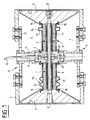
- Figure 1 is an axial sectional view of a transducer of the above type, equipped with two types of devices according to the invention.
- Figure 2 is another view in axial section with two other examples of devices according to the invention.
- the transducers as shown in section in these Figures 1 and 2 therefore comprise in a known manner, two electro-acoustic motors 1 aligned on an axis xx ', placed on either side of a central counterweight 2 and coaxially inside a cylindrical housing 5, which can be called external, covering all of said motors 1 up to the pavilions 3 at the end thereof, the cavity 7, thus delimited by said pavilions , and said housing being filled with liquid 4 in which the whole of the transducer is immersed, such as sea water.
- the characteristics and dimensions of the different parts constituting this assembly as well as of the other elements not shown in these figures, since this is not the aim of the present invention, are such that the Helmholtz frequency of the cavity 7 determined by the housing is close to the fundamental frequency of the axial vibrations of the assembly formed by said electro-acoustic motors 1, said counterweight 2 and said pavilions 3.
- said electro-acoustic motors and the intermediate mass 2 are shown assembled by means of different connecting parts 11, themselves connected to different fixing parts 12, connecting said electro-acoustic motors to the external housing 5.
- the various fastening means are such that they allow freedom of movement, on the one hand of the ends of the electro-acoustic motors on the side of the pavilions, and on the other hand, of the pavilions 3 themselves end relative to said box 5, so as to ensure the full emission of low frequency acoustic waves in the ambient environment.
- the power supply of said electro-acoustic motors 1 is supplied by any power cable 10 fixed to said connection parts 11 by an electrical connector 14.
- the production of such a transducer and all of the various connection parts constituting it are from the field known and achievable by any person skilled in the art: all the other elements making it possible to obtain the Helmholtz frequency as defined above, are not shown here and some have been the subject of various other patent applications such as those in particular cited in the introduction.
- said external housing 5 comprises at least one opening 6 for communication with the outside, said opening possibly consisting of holes distributed around the cylindrical part of the housing or even consisting of a complete circular peripheral opening; moreover, the fact that the cavity 7 is not sealed and communicates with the outside, said end pavilions 3 are not connected at their periphery to the housing 5 and can therefore have freedom of movement all the more.
- the device sealing according to the present invention of the electro-acoustic motors 1 of said submersible transducer, and which are of cylindrical shape with axis xx ', comprises casings 8 also cylindrical, a large part of which closely matches the shape of said motors 1 on their entire length and against their external surface; the other part of the casings 8 consists of a discontinuity 9, giving a capacity for longitudinal elasticity of deformation of the housing 8, in the direction of the axis xx 'of said motors 1.
- said envelopes 8 are closed and sealed both of course along their cylindrical part, and their discontinuity, and at their ends where they are associated with any system of fixing 16, 17 to constitute a sealed box: at one end, they are fixed in a sealed manner to the part 3 integral with the motor 1 and ensuring the emission of the waves emitted by the latter and at the other end to the part 2 blocking the other end of said motor 1.
- the device also preferably comprises a thin film 13 of electrically insulating material, situated against the external surface of said electro-acoustic motors; this said film 13 does not provide a pressure resistance or sealing function, and therefore does not need to be very thick.
- said envelopes 8 are made of a material whose thermal conductivity is high, such as in particular metal or composite resin.
- said discontinuity 9 is produced by at least one fold 92 of small "U" section square in any plane passing through the axis xx '.
- said discontinuity 9 is produced by at least two folds 91 of small sinusoidal section in any plane passing through the axis xx ': in these two embodiments, the folds 91, 92 are of a sufficiently small radius of curvature, so that despite the small thickness of the material constituting the envelopes 8, they can withstand the external pressure, and this small thickness of the material of the envelopes allows the longitudinal elasticity xx 'necessary, thanks to the 'existence said folds making a spring effect.
- said discontinuity 9 is produced by two flanges 9 each situated at the end of two elements 8 phobia, 82 constituting the large continuous part of the casing 8, which flanges being separated and assembled in one sealingly by an elastic seal 15 comprising fixing bolts connected to only one of said flanges and of sufficient thickness to allow the axial displacement of the two elements 81 and 82 relative to each other.
- said discontinuity 9 is produced by a concentric interlocking 93 between two elements 81, 82 also constituting the large continuous part of the casing 8, one of which 82 is sandwiched between the external surface of the motor 1 and the internal surface of the other element 81; it has a part 15 concentric outside the other 82 more extensive than the end of the latter; a seal 18 seals between these two elements, which can thus move axially relative to one another.
- the device comprises two envelopes 8 and each envelope is fixed in a sealed manner at one end 16 to the corresponding flag 3 to the motor 1 concerned and ensuring the emission of the waves emitted by it and at the other end 17, to the central counterweight 2 blocking the other ends of said motors 1.
Landscapes
- Engineering & Computer Science (AREA)
- Mechanical Engineering (AREA)
- Physics & Mathematics (AREA)
- Acoustics & Sound (AREA)
- Signal Processing (AREA)
- Transducers For Ultrasonic Waves (AREA)
- Measurement Of Velocity Or Position Using Acoustic Or Ultrasonic Waves (AREA)
- Audible-Bandwidth Dynamoelectric Transducers Other Than Pickups (AREA)
- Motor Or Generator Frames (AREA)
Claims (8)
- Abdichtung von elektroakustischen Motoren in eine Flüssigkeit (4) eintauchbarer Wandler zylindrischer Form und beliebigen Querschnitts entlang einer Achse xx'. Diese Abdichtung zeichnet sich dadurch aus, daß sie eine ebenfalls zylindrische und konzentrische (8) Ummantelung aufweist. Ein großer Teil dieser Ummantelung paßt sich so weit wie möglich der Form des besagten Motors (1) auf dessen gesamter Länge an die äußere Oberfläche an. Der andere Teil der Ummantelung (8) weist eine Unterbrechung beziehungsweise Ausbuchtung (9) auf, was der Ummantelung (8) eine Elastizität in Längsrichtung entlang der Achse xx' des Motors (1) verleiht. Die Ummantelung (8) ist geschlossen, aus einem Material mit hoher Wärmeleitfähigkeit und an den Enden mit einem beliebigen Befestigungssystem (16,17) fixiert, um ein wasserdichtes Gehäuse zu bilden.
- Abdichtung entsprechend Patentanspruch 1, wobei die Ausbuchtung (9) mittels mindestens eines kleinen Falzes (9₂) eckigen U-förmigen Querschnitts realisiert ist. Diese Falze liegen auf allen Ebenen, die durch die Achse xx' führen.
- Abdichtung entsprechend Patentanspruch 1, wobei die Ausbuchtung (9) mittels mindestens zweier kleiner Falze (9₁) geschwungenen U-förmigen Querschnitts realisiert ist. Diese Falze liegen auf allen Ebenen, die durch die Achse xx' führen.
- Abdichtung entsprechend Patentanspruch 1, wobei die Unterbrechung (9) mittels einer konzentrischen Überlappung (9₃) der beiden Elementen (8₁, 8₂), die den großen ununterbrochenen Teil der Ummantelung (8) bilden. Das eine Element (8₂) ist zwischen der äußeren Oberfläche des Motors (1) und der inneren Oberfläche des anderen Elementes (8₁) eingelagert. Letzteres hat einen konzentrischen Teil (15), der außerhalb des anderen (8₂) liegt, wobei das Teil (8₁) das äußere Ende des Teiles (8₂) überlappt.
- Abdichtung entsprechend Patentanspruch 1, wobei die Unterbrechung (9) mittels zweier Flansche (9₄) realisiert ist, die jeweils auf den äußeren Enden der Teile (8₁, 8₂) liegen, die einen großen ununterbrochenen Teil der Ummantelung (8) bilden. Diese Flansche sind getrennt und mit Hilfe einer elastichen Dichtung (15) wasserdicht verbunden, die Befestigungsschrauben aufweist, die an einem einzigen der besagten Flansche befestigt sind.
- Abdichtung entsprechend eines beliebigen der Patentansprüche 1 bis 5, wobei sie eine dünne Folie (13) Elektroisoliermaterials aufweist, die auf der äußeren Oberfläche des besagten elektroakustischen Motors liegt. So wird jedweder direkter Kontakt des besagten Motors mit der besagten Ummantelung (8) vermieden.
- Abdichtung entsprechend eines beliebigen der Patentansprüche 1 bis 6, die sich dadurch auszeichnet, daß die besagte Ummantelung (8) wasserdicht an einem der Enden des Teils (3) befestigt ist, das fest mit dem Motor 1 verbunden ist und die Emmission der durch selbigen produzierten Schallwellen gewährleistet. Das andere Ende der Ummantelung ist an dem Teil (2) angebracht, das das andere Ende des besagten Motors (1) blockiert.
- Abdichtung gemäß Patentanspruch (7), die dadurch gekennzeichnet ist, daß sie bei einem Wandler Anwendung findet, der über zwei elektroakustische Motoren (1) verfügt, die in gerader Linie auf der Achse xx' angeordnet sind. Ein Motor ist auf der einen Seite der zentralen Gegenmasse (2), der andere auf der anderen Seite derselben koaxial im Inneren des zylindrischen Gehäuses plaziert. Das Gehäuse ist hohl (5), deckt die beiden Motoren (1) bis zum äußeren Rand des Trichters (3) ab und ist mit besagter Flüssigkeit (4) angefüllt. Diese Abdichtung besteht aus zwei Ummantelungen (8), die jeweils an einem Ende (16) wasserdicht auf dem Trichter (3) befestigt sind, der zu dem betreffenden Motor (1) gehört. Das andere Ende (17) ist auf der gemeinsamen Gegenmasse (2) angebracht.
Applications Claiming Priority (2)
| Application Number | Priority Date | Filing Date | Title |
|---|---|---|---|
| FR9213301A FR2697709B1 (fr) | 1992-11-05 | 1992-11-05 | Dispositif d'étanchéité de moteurs électro-acoustiques. |
| FR9213301 | 1992-11-05 |
Publications (2)
| Publication Number | Publication Date |
|---|---|
| EP0600758A1 EP0600758A1 (de) | 1994-06-08 |
| EP0600758B1 true EP0600758B1 (de) | 1995-08-02 |
Family
ID=9435244
Family Applications (1)
| Application Number | Title | Priority Date | Filing Date |
|---|---|---|---|
| EP19930402495 Expired - Lifetime EP0600758B1 (de) | 1992-11-05 | 1993-10-11 | Dichtungsvorrichtung für elektro-akustische Motoren |
Country Status (5)
| Country | Link |
|---|---|
| EP (1) | EP0600758B1 (de) |
| CA (1) | CA2109465C (de) |
| DE (1) | DE69300325T2 (de) |
| ES (1) | ES2078809T3 (de) |
| FR (1) | FR2697709B1 (de) |
Families Citing this family (5)
| Publication number | Priority date | Publication date | Assignee | Title |
|---|---|---|---|---|
| FR2720587B1 (fr) * | 1994-05-26 | 1996-07-05 | France Etat Armement | Perfectionnement aux antennes sonar munies d'une contre masse commune. |
| EP0684085A1 (de) * | 1994-05-26 | 1995-11-29 | ETAT FRANCAIS Représenté par le Délégué Général pour l'Armement | Offene Sonar-Anordnung mit elektroakustische Wandler |
| FR2720585B1 (fr) * | 1994-05-26 | 1996-07-05 | France Etat Armement | Transducteur électro acoustique antenne sonar ouverts. |
| FR2728425B1 (fr) * | 1994-12-15 | 1997-01-31 | France Etat Armement | Antenne lineaire electroacoustique d'emission et antenne d'emission/reception comprenant une telle antenne |
| FR2779533B1 (fr) * | 1998-06-09 | 2000-08-25 | Total Sa | Dispositif d'acquisition sismique a haute resolution |
Family Cites Families (5)
| Publication number | Priority date | Publication date | Assignee | Title |
|---|---|---|---|---|
| FR2361033A1 (fr) * | 1976-08-03 | 1978-03-03 | France Etat | Transducteurs piezoelectriques et antennes acoustiques immergeables a grande profondeur |
| WO1987003448A1 (en) * | 1985-11-30 | 1987-06-04 | Ferranti Plc | Tubular acoustic projector |
| FR2665998B1 (fr) * | 1988-05-05 | 1993-10-29 | Etat Francais Delegue Armement | Procedes et transducteurs electro-acoustiques pour emettre des ondes acoustiques a basse frequence dans un liquide. |
| FR2634292B1 (fr) * | 1988-07-15 | 1990-10-19 | Grosso Gilles | Procede et dispositifs pour maintenir le gaz contenu dans une enceinte immergee en equilibre de pression avec l'exterieur |
| US5103130A (en) * | 1988-12-20 | 1992-04-07 | Rolt Kenneth D | Sound reinforcing seal for slotted acoustic transducers |
-
1992
- 1992-11-05 FR FR9213301A patent/FR2697709B1/fr not_active Expired - Fee Related
-
1993
- 1993-10-11 ES ES93402495T patent/ES2078809T3/es not_active Expired - Lifetime
- 1993-10-11 DE DE1993600325 patent/DE69300325T2/de not_active Expired - Fee Related
- 1993-10-11 EP EP19930402495 patent/EP0600758B1/de not_active Expired - Lifetime
- 1993-10-28 CA CA 2109465 patent/CA2109465C/fr not_active Expired - Fee Related
Also Published As
| Publication number | Publication date |
|---|---|
| DE69300325T2 (de) | 1996-04-18 |
| FR2697709B1 (fr) | 1994-12-30 |
| CA2109465C (fr) | 2002-01-22 |
| ES2078809T3 (es) | 1995-12-16 |
| EP0600758A1 (de) | 1994-06-08 |
| CA2109465A1 (fr) | 1994-05-06 |
| FR2697709A1 (fr) | 1994-05-06 |
| DE69300325D1 (de) | 1995-09-07 |
Similar Documents
| Publication | Publication Date | Title |
|---|---|---|
| EP0462037B1 (de) | Elektroakustischer Unterwasserwandler | |
| EP2670536B1 (de) | Elektroakustischer niederfrequenzwandler und verfahren zur erzeugung von schallwellen | |
| US8508107B2 (en) | Low frequency oscillator, the omni-directional type low frequency underwater acoustic transducer using the same and the cylindrical radiation type low frequency underwater acoustic transducer using the same | |
| EP0600758B1 (de) | Dichtungsvorrichtung für elektro-akustische Motoren | |
| EP0367681A1 (de) | Flexionsgespannter Wandler | |
| CH691335A5 (fr) | Appareil susceptible d'être immergé et comprenant un transducteur sonore. | |
| EP0728535B1 (de) | Verfahren und Vorrichtung zur Verminderung der Resonanzfrequenz von Hohlräumen von Unterwasserwandlern | |
| FR2720589A1 (fr) | Procédé et transducteur pour émettre des ondes acoustiques à larges bandes et basses fréquences en profondeur d'immersion illimitée. | |
| EP0247126A1 (de) | Rohrförmiger, akustischer sender. | |
| EP0656232B1 (de) | Verfahren zum Hochleistungsemission von akustischen Wellen und damit übereinstimmende Wandlerhorne | |
| FR2797552A1 (fr) | Transducteur electro-acoustique | |
| EP0118329B1 (de) | Geschwindigkeitshydrophon | |
| FR2688972A1 (fr) | Transducteurs electro-acoustiques comportant une coque emettrice flexible et etanche. | |
| EP0636810A1 (de) | Verbesserung an den Gegenschwingungslagern von Hubschrauberrotorflügeln, und Hubschrauberrotor mit solchen Lagern | |
| FR2748183A1 (fr) | Hydrophone et procede pour sa fabrication | |
| EP0596763B1 (de) | Verfahren und Wandler zum Aussenden von niederfrequenten akustischen Wellen, welcher in einer Flüssigkeit unbeschränkt eingetaucht ist | |
| EP0728534B1 (de) | Verfahren und in einer Flussigkeit versekter Handler mit leichten Strahler zum Aussenden von niederfrequenten akustischen Wellen | |
| FR2739521A1 (fr) | Transducteur electroacoustique et antenne de sonar equipee d'un tel transducteur | |
| FR2569326A1 (fr) | Transducteurs piezo-electriques et antennes de sonar pouvant etre immerges a grande profondeur | |
| FR2701340A1 (fr) | Procédé de réalisation d'un circuit de distribution de signaux électriques, circuit de distribution obtenu et moteur piézoélectrique comportant un tel circuit. | |
| FR2728425A1 (fr) | Antenne lineaire electroacoustique d'emission et antenne d'emission/reception comprenant une telle antenne | |
| FR2764160A1 (fr) | Transducteur electrodynamique pour acoustique sous-marine | |
| EP0657868B1 (de) | Verfahren und Wandler zum Aussenden von sehr niederfrequenten akustischen Wellen mit grosser Leistung | |
| FR2720585A1 (fr) | Transducteur électro acoustique antenne sonar ouverts. | |
| FR2697710A1 (fr) | Procédé et transducteur pour émettre des ondes acoustiques de très basses fréquences, dans un liquide en immersion illimitée. |
Legal Events
| Date | Code | Title | Description |
|---|---|---|---|
| PUAI | Public reference made under article 153(3) epc to a published international application that has entered the european phase |
Free format text: ORIGINAL CODE: 0009012 |
|
| 17P | Request for examination filed |
Effective date: 19931026 |
|
| AK | Designated contracting states |
Kind code of ref document: A1 Designated state(s): DE ES GB IT NL |
|
| 17Q | First examination report despatched |
Effective date: 19941017 |
|
| GRAA | (expected) grant |
Free format text: ORIGINAL CODE: 0009210 |
|
| AK | Designated contracting states |
Kind code of ref document: B1 Designated state(s): DE ES GB IT NL |
|
| PG25 | Lapsed in a contracting state [announced via postgrant information from national office to epo] |
Ref country code: GB Effective date: 19950802 |
|
| REF | Corresponds to: |
Ref document number: 69300325 Country of ref document: DE Date of ref document: 19950907 |
|
| ITF | It: translation for a ep patent filed | ||
| REG | Reference to a national code |
Ref country code: ES Ref legal event code: FG2A Ref document number: 2078809 Country of ref document: ES Kind code of ref document: T3 |
|
| GBV | Gb: ep patent (uk) treated as always having been void in accordance with gb section 77(7)/1977 [no translation filed] |
Effective date: 19950802 |
|
| PLBE | No opposition filed within time limit |
Free format text: ORIGINAL CODE: 0009261 |
|
| STAA | Information on the status of an ep patent application or granted ep patent |
Free format text: STATUS: NO OPPOSITION FILED WITHIN TIME LIMIT |
|
| 26N | No opposition filed | ||
| PGFP | Annual fee paid to national office [announced via postgrant information from national office to epo] |
Ref country code: NL Payment date: 20060921 Year of fee payment: 14 |
|
| PGFP | Annual fee paid to national office [announced via postgrant information from national office to epo] |
Ref country code: DE Payment date: 20061009 Year of fee payment: 14 |
|
| PGFP | Annual fee paid to national office [announced via postgrant information from national office to epo] |
Ref country code: ES Payment date: 20061016 Year of fee payment: 14 |
|
| PGFP | Annual fee paid to national office [announced via postgrant information from national office to epo] |
Ref country code: IT Payment date: 20061031 Year of fee payment: 14 |
|
| NLV4 | Nl: lapsed or anulled due to non-payment of the annual fee |
Effective date: 20080501 |
|
| PG25 | Lapsed in a contracting state [announced via postgrant information from national office to epo] |
Ref country code: DE Free format text: LAPSE BECAUSE OF NON-PAYMENT OF DUE FEES Effective date: 20080501 |
|
| PG25 | Lapsed in a contracting state [announced via postgrant information from national office to epo] |
Ref country code: NL Free format text: LAPSE BECAUSE OF NON-PAYMENT OF DUE FEES Effective date: 20080501 |
|
| REG | Reference to a national code |
Ref country code: ES Ref legal event code: FD2A Effective date: 20071013 |
|
| PG25 | Lapsed in a contracting state [announced via postgrant information from national office to epo] |
Ref country code: ES Free format text: LAPSE BECAUSE OF NON-PAYMENT OF DUE FEES Effective date: 20071013 |
|
| PG25 | Lapsed in a contracting state [announced via postgrant information from national office to epo] |
Ref country code: IT Free format text: LAPSE BECAUSE OF NON-PAYMENT OF DUE FEES Effective date: 20071011 |