EP0596763B1 - Verfahren und Wandler zum Aussenden von niederfrequenten akustischen Wellen, welcher in einer Flüssigkeit unbeschränkt eingetaucht ist - Google Patents
Verfahren und Wandler zum Aussenden von niederfrequenten akustischen Wellen, welcher in einer Flüssigkeit unbeschränkt eingetaucht ist Download PDFInfo
- Publication number
- EP0596763B1 EP0596763B1 EP19930402496 EP93402496A EP0596763B1 EP 0596763 B1 EP0596763 B1 EP 0596763B1 EP 19930402496 EP19930402496 EP 19930402496 EP 93402496 A EP93402496 A EP 93402496A EP 0596763 B1 EP0596763 B1 EP 0596763B1
- Authority
- EP
- European Patent Office
- Prior art keywords
- casing
- opening
- transducer
- liquid
- mass
- Prior art date
- Legal status (The legal status is an assumption and is not a legal conclusion. Google has not performed a legal analysis and makes no representation as to the accuracy of the status listed.)
- Expired - Lifetime
Links
Images
Classifications
-
- B—PERFORMING OPERATIONS; TRANSPORTING
- B06—GENERATING OR TRANSMITTING MECHANICAL VIBRATIONS IN GENERAL
- B06B—METHODS OR APPARATUS FOR GENERATING OR TRANSMITTING MECHANICAL VIBRATIONS OF INFRASONIC, SONIC, OR ULTRASONIC FREQUENCY, e.g. FOR PERFORMING MECHANICAL WORK IN GENERAL
- B06B1/00—Methods or apparatus for generating mechanical vibrations of infrasonic, sonic, or ultrasonic frequency
- B06B1/02—Methods or apparatus for generating mechanical vibrations of infrasonic, sonic, or ultrasonic frequency making use of electrical energy
- B06B1/06—Methods or apparatus for generating mechanical vibrations of infrasonic, sonic, or ultrasonic frequency making use of electrical energy operating with piezoelectric effect or with electrostriction
- B06B1/0607—Methods or apparatus for generating mechanical vibrations of infrasonic, sonic, or ultrasonic frequency making use of electrical energy operating with piezoelectric effect or with electrostriction using multiple elements
- B06B1/0611—Methods or apparatus for generating mechanical vibrations of infrasonic, sonic, or ultrasonic frequency making use of electrical energy operating with piezoelectric effect or with electrostriction using multiple elements in a pile
- B06B1/0618—Methods or apparatus for generating mechanical vibrations of infrasonic, sonic, or ultrasonic frequency making use of electrical energy operating with piezoelectric effect or with electrostriction using multiple elements in a pile of piezo- and non-piezoelectric elements, e.g. 'Tonpilz'
Definitions
- the present invention relates to methods for emitting low frequency acoustic waves in a liquid in unlimited immersion, and transducers which allow the implementation of such methods.
- the technical sector of the invention is that of the production of electro-acoustic transducers.
- the main application of the invention is the possibility of emitting acoustic waves at low frequencies and at very great depth.
- Immersible electro-acoustic transducers and in particular piezoelectric transducers, are known which comprise a rigid cylindrical housing, hollow and open at its two axial ends, and inside which two motors are arranged coaxially with it.
- identical electro-acoustics placed on either side of a central counter-mass, and whose opposite ends are surrounded by a flag.
- Said electroacoustic motors can be produced by two stacks of aligned piezoelectric plates.
- the external faces of the two flags are located in the plane of the axial ends of the housing, so that they are in contact with the liquid, in which the housing is immersed, and the external perimeter of these flags comes as close as possible to the edge. open axial ends of said housing.
- these external faces emit acoustic waves into the liquid when the electro-acoustic motors are electronically excited: these transducers are used in particular to emit low-frequency acoustic waves in water in a determined direction.
- the second category of solution overcomes the above mechanical and / or pneumatic problems, as described in the patent application FR. 2.665.998 OF 05 May 1988 filed by the French State General Delegate for Armaments: it consists in using a rigid case, but not waterproof, making it possible to delimit a cavity filled with ambient liquid behind the pavilions, in which closed elastic tubes, sealed and filled with gas, are placed such that the Helmholtz resonance frequency of the cavity is close to the fundamental frequency of the axial vibrations of the vibrating assembly.
- the problem is to be able to emit waves acoustics of low frequencies in a liquid, without limitation of depth and without weighing down or increasing the volume and / or the complexity of realization of the transducers.
- each of the two edges of said opening is associated with a crown of material resistant to pressure and then forming an integral part of said housing of which they are integral.
- the result is new transducers and methods for emitting low frequency acoustic waves into a liquid at great depth.
- this resonant frequency in the previous patent application is obtained by combining the elasticity of tubes located in said housing and the body of water located in the opening made in the rigid cylinder constituting said housing, while in the present invention, the cylinder is no longer rigid but on the contrary must be elastic, allowing thus have the same function and therefore eliminate the presence of the tubes required in the above patent application; the mass or inertia function of the previous patent application is always obtained, but increased in the present invention by the presence, of a greater mass of water in the mouth of the opening thanks to the possibility of add crowns around the openings, which was not previously possible because of the presence of the tubes.
- Similar effects are obtained overall, even if the performance is less good, this makes it possible to precisely meet the needs of great and therefore even unlimited depths of the present invention. This is therefore new and different from the characteristics of all patent applications and existing equipment.
- the present invention is the elasticity of the housing by coupling with the mass of water located in the opening made in said housing which, by breaking the impedance, stops the rear waves emitted by the rear faces of the pavilions.
- this elasticity is improved on the one hand and, on the other hand, the importance of said body of water by preferably adding circular plates or crowns to the ends of the edges of said opening: thus by changing the characteristics of said housing by modifying its elasticity and its dimensions and / or those of said crowns, the mass of water located in the opening is increased and the inertia is changed of this said housing, which allows the emission of even lower frequencies.
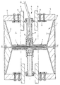
- the attached single figure is an axial sectional view of a transducer according to the present invention.
- the transducer as shown in section in this figure comprises, in a known manner, two electro-acoustic motors 1, aligned along an axis xx ', placed on either side of a central counterweight 2, and coaxially inside a cylindrical housing 5, covering all of said motors 1 up to the pavilion 3 at the end thereof, the cavity 7 thus delimited by the rear of said pavilions and said housing being filled with said liquid 4 .
- Said electro-acoustic motors 1 can be of the piezoelectric type, but also magnetostrictive cylinders surrounded by an excitation coil.
- Such electro-acoustic transducers with double motors are also called double Tonpilz.
- said electro-acoustic motors and the intermediate mass 2 are shown assembled assembled by means of different connecting parts 11, themselves connected to different fixing parts 12, connecting said electro-acoustic motors to the housing 5 thanks to all fixing means and allowing freedom of movement of the end flags 3 relative to said housing, but determining an internal cavity 7 almost closed between the respective edges 13 of said flags and said housing.
- the power supply of said electro-acoustic motors 1 is supplied by any power cable 10, fixed to said connecting parts 11 by an electrical connector 14.
- the production of such a transducer and all of the various parts constituting it are of the field known and achievable by any person skilled in the art.
- said housing 5 is made of elastic material resistant to immersion pressure; in addition, it has a circular peripheral opening 6 in the vicinity of its median plane and the dimensions of said opening 6 as well as the characteristics of the material constituting said housing, in particular its elasticity characteristics, and the dimensions of this determining the inertial mass of this assembly are such that by coupling the elasticity of the housing 5 with the mass of the liquid 4 located in said opening 6, the Helmholtz frequency of the cavity 7 determined by the housing is close to the fundamental frequency of the vibrations axial of the assembly formed by said electro-acoustic motors 1, said counterweight 2 and said pavilions 3.
- said Helmholtz frequency of cavity 7 is determined such that it is less than said fundamental frequency.
- said edges of said opening 6 are each associated with a crown 8 of material resistant to pressure and which can therefore be of the same material as that of said cylinder 5 to which it is integral and forms an integral part.
- Said crowns 8 are circular plates preferably located inside said housing 5, so as not to increase its size, but they could be located on either side of said opening or even only outside.
- this opening 6 is symmetrical relative to the median plane perpendicular to the axis xx 'of the transducer.
- the material used for the production of said housing 5 and said rings or circular plates 8 can be metal or composite fiber such as carbon fiber.
Landscapes
- Engineering & Computer Science (AREA)
- Mechanical Engineering (AREA)
- Transducers For Ultrasonic Waves (AREA)
- Apparatuses For Generation Of Mechanical Vibrations (AREA)
Claims (8)
- Verfahren zur Sendung von Niedrigfrequenzschallwellen in einer Flüssigkeit (4) mittels eines Wandlers, bestehend aus zwei auf einer Achse (xx') ausgerichteten elektro-akustischen Motoren (1), die auf beiden Seiten einer mittleren Gegenmasse (2) und koaxial innerhalb eines hohen zylindrischen Kastens (5) angeordnet sind, wobei der Kasten die besagten Motoren (1) bis hin zu ihren Endtrichtern (3) überdeckt und mit der besagten Flüssigkeit (4) gefüllt ist, dadurch gekennzeichnet, dass:. man den Kasten (5) aus elastischem und druckbeständigem Material herstellt, mit einer kreisförmigen periphären Öffnung (6) in der Nähe seiner mittleren Ebene;. man die Abmessungen der besagten Öffnung (6) und die Merkmale des besagten Kastens (5) so festlegt, dass durch Kopplung der Elastizität dieses Kastens mit der in der besagten Öffnung (6) vorhandenen Flüssigkeitsmasse, die Helmholtz-Frequenz der vom Kasten bezeichneten Vertiefung (7) in der Nähe der Eigenfrequenz der axialen Vibrationen der aus den besagten elektro-akustischen Motoren (1), der besagten Gegenmasse (2) und den besagten Trichtern (3) gebildeten Einheit liegt.
- Verfahren zur Sendung von Niedrigfrequenzschallwellen in einer Flüssigkeit (4) nach Anspruch 1, dadurch gekennzeichnet, dass man jedem der beiden Ränder (9) der besagten Öffnung (6) eine Krone (8) aus druckbeständigem Material zuordnet, die dann Bestandteil des besagten Kastens (5) sind, mit dem sie ein Stück bilden.
- Verfahren nach einer der Ansprüche 1 und 2, dadurch gekennzeichnet, dass man die in der Öffnung (6) vorhandene Wassermasse erhöht und die Trägheit des besagten Kastens (5) abändert, indem man seine Abmessungen ändert, um die Sendung von niedrigeren Frequenzen zu ermöglichen.
- Wandler mit zwei elektro-akustischen Motoren (1), die nach einer Achse (xx') ausgerichtet, auf jeder Seite einer mittleren Gegenmasse (2) und koaxial innerhalb eines hohen zylindrischen Kastens (5) angeordnet sind, wobei der Kasten die Einheit der besagten Motoren (1) bis zum an ihren Enden angeordneten Trichter (3) überdeckt, dadurch gekennzeichnet, dass der besagte Kasten (5) aus einem druckbeständigen und elastischen Material besteht und eine periphäre, kreisförmige Öffnung (6) in der Nähe seiner mittleren Ebene aufweist, und deren Abmessungen Sowie die Merkmale des besagten Kastens so beschaffen sind, dass durch Kupplung der Elastizität des Kastens (5) mit der Masse der in der besagten Öffnung (6) vorhandenen Flüssigkeit (4), die Helmholtz-Frequenz der vom Kasten definierten Vertiefung (7) in der Nähe der Eigenfrequenz der axialen Vibrationen der von den besagten elektro-akustischen Motoren (1), der besagten Gegenmasse (2) und den besagten Trichtern (3) gebildeten Einheit liegt.
- Wandler zur Sendung von Niedrigfrequenzschallwellen in einer Flüssigkeit (4) nach Anspruch 4, dadurch gekennzeichnet, dass den besagten Rändern der besagten Öffnung (6) jeweils eine Krone (8) aus druckbeständigem Material zugeordnet ist, die Bestandteil des Kastens (5) sind und mit ihm ein Stück bilden.
- Wandler nach Anspruch 5, dadurch gekennzeichnet, dass es sich bei den besagten Kronen (8) um kreisförmige Platten handelt, die völlig innerhalb des besagten Kastens (5) angeordnet werden.
- Wandler nach einem der Ansprüche 4 bis 6, dadurch gekennzeichnet, dass die Öffnung (6) symmetrisch in bezug auf die mittlere, senkrecht zur Achse xx' des Wandlers verlaufenden Ebene ist.
- Wandler nach einem der Ansprüche 4 bis 7, dadurch gekennzeichnet, dass es sich bei den besagten Motoren (1) um magnetostriktive, von einer Erregungsspule umgebene Zylinder handelt.
Applications Claiming Priority (2)
| Application Number | Priority Date | Filing Date | Title |
|---|---|---|---|
| FR9213303 | 1992-11-05 | ||
| FR9213303A FR2697711B1 (fr) | 1992-11-05 | 1992-11-05 | Procédé et transducteur pour émettre des ondes acoustiques basse fréquence dans un liquide en immersion illimitée. |
Publications (2)
| Publication Number | Publication Date |
|---|---|
| EP0596763A1 EP0596763A1 (de) | 1994-05-11 |
| EP0596763B1 true EP0596763B1 (de) | 1995-08-09 |
Family
ID=9435246
Family Applications (1)
| Application Number | Title | Priority Date | Filing Date |
|---|---|---|---|
| EP19930402496 Expired - Lifetime EP0596763B1 (de) | 1992-11-05 | 1993-10-11 | Verfahren und Wandler zum Aussenden von niederfrequenten akustischen Wellen, welcher in einer Flüssigkeit unbeschränkt eingetaucht ist |
Country Status (5)
| Country | Link |
|---|---|
| EP (1) | EP0596763B1 (de) |
| CA (1) | CA2109466C (de) |
| DE (1) | DE69300365T2 (de) |
| ES (1) | ES2078810T3 (de) |
| FR (1) | FR2697711B1 (de) |
Families Citing this family (3)
| Publication number | Priority date | Publication date | Assignee | Title |
|---|---|---|---|---|
| FR2720589B1 (fr) * | 1994-05-27 | 1996-07-05 | France Etat Armement | Procédé et transducteur pour émettre des ondes acoustiques à larges bandes et basses fréquences en profondeur d'immersion illimitée. |
| FR2731128B1 (fr) * | 1995-02-23 | 1997-04-11 | France Etat | Procede et transducteurs immerges dans un fluide pour l'emission d'ondes acoustiques a basse frequence avec des pavillons alleges |
| CN116532349B (zh) * | 2023-06-07 | 2024-01-30 | 中国科学院声学研究所 | 复合驱动的亥姆赫兹换能器 |
Family Cites Families (6)
| Publication number | Priority date | Publication date | Assignee | Title |
|---|---|---|---|---|
| FR2361033A1 (fr) * | 1976-08-03 | 1978-03-03 | France Etat | Transducteurs piezoelectriques et antennes acoustiques immergeables a grande profondeur |
| FR2665998B1 (fr) * | 1988-05-05 | 1993-10-29 | Etat Francais Delegue Armement | Procedes et transducteurs electro-acoustiques pour emettre des ondes acoustiques a basse frequence dans un liquide. |
| FR2634292B1 (fr) * | 1988-07-15 | 1990-10-19 | Grosso Gilles | Procede et dispositifs pour maintenir le gaz contenu dans une enceinte immergee en equilibre de pression avec l'exterieur |
| FR2663182B1 (fr) * | 1990-06-12 | 1992-09-18 | Grosso Gilles | Transducteur electro-acoustique immerge. |
| FR2665814B1 (fr) * | 1990-08-10 | 1993-06-11 | Thomson Csf | Transducteur electroacoustique destine a etre immerge et comportant un systeme de compensation automatique de la pression d'immersion. |
| FR2673347B1 (fr) * | 1991-02-22 | 1993-05-07 | Thomson Csf | Transducteur electroacoustique a decouplage acoustique optimise. |
-
1992
- 1992-11-05 FR FR9213303A patent/FR2697711B1/fr not_active Expired - Fee Related
-
1993
- 1993-10-11 DE DE1993600365 patent/DE69300365T2/de not_active Expired - Fee Related
- 1993-10-11 ES ES93402496T patent/ES2078810T3/es not_active Expired - Lifetime
- 1993-10-11 EP EP19930402496 patent/EP0596763B1/de not_active Expired - Lifetime
- 1993-10-28 CA CA 2109466 patent/CA2109466C/fr not_active Expired - Fee Related
Also Published As
| Publication number | Publication date |
|---|---|
| EP0596763A1 (de) | 1994-05-11 |
| FR2697711B1 (fr) | 1994-12-30 |
| FR2697711A1 (fr) | 1994-05-06 |
| DE69300365T2 (de) | 1996-04-04 |
| CA2109466A1 (fr) | 1994-05-06 |
| DE69300365D1 (de) | 1995-09-14 |
| ES2078810T3 (es) | 1995-12-16 |
| CA2109466C (fr) | 2002-01-22 |
Similar Documents
| Publication | Publication Date | Title |
|---|---|---|
| EP2670536B1 (de) | Elektroakustischer niederfrequenzwandler und verfahren zur erzeugung von schallwellen | |
| EP1222653B1 (de) | Breitbandiger unterwasser-schallwandler | |
| CA2150297C (fr) | Procede et transducteur pour emettre des ondes acoustiques a larges bandes et basses frequences en profondeur d'immersion illimitee | |
| EP3359308B1 (de) | Sendeempfängervorrichtung für breitbandige unterwasserakustik | |
| FR2665998A1 (fr) | Procedes et transducteurs electro-acoustiques pour emettre des ondes acoustiques a basse frequence dans un liquide. | |
| EP0728535B1 (de) | Verfahren und Vorrichtung zur Verminderung der Resonanzfrequenz von Hohlräumen von Unterwasserwandlern | |
| EP3198586B1 (de) | Rundstrahlantenne | |
| EP0596763B1 (de) | Verfahren und Wandler zum Aussenden von niederfrequenten akustischen Wellen, welcher in einer Flüssigkeit unbeschränkt eingetaucht ist | |
| EP0656232B1 (de) | Verfahren zum Hochleistungsemission von akustischen Wellen und damit übereinstimmende Wandlerhorne | |
| EP3677051B1 (de) | Wasserschallgehäuse | |
| CA2109465C (fr) | Dispositif d'etancheite de moteurs electro-acoustiques | |
| FR2688972A1 (fr) | Transducteurs electro-acoustiques comportant une coque emettrice flexible et etanche. | |
| EP0657868B1 (de) | Verfahren und Wandler zum Aussenden von sehr niederfrequenten akustischen Wellen mit grosser Leistung | |
| EP0728534B1 (de) | Verfahren und in einer Flussigkeit versekter Handler mit leichten Strahler zum Aussenden von niederfrequenten akustischen Wellen | |
| FR2697710A1 (fr) | Procédé et transducteur pour émettre des ondes acoustiques de très basses fréquences, dans un liquide en immersion illimitée. | |
| FR2569326A1 (fr) | Transducteurs piezo-electriques et antennes de sonar pouvant etre immerges a grande profondeur | |
| CA2038737C (fr) | Procedes et transducteurs electro-acoustiques pour emettre des ondes acoustiques a basse frequence dans un liquide | |
| FR2664782A1 (fr) | Enceinte acoustique omnidirectionnelle. | |
| FR2673347A1 (fr) | Transducteur electroacoustique a decouplage acoustique optimise. | |
| EP0728533B1 (de) | Verfahren und Wandler zum Aussenden von akustischen Wellen in einer Flüssigkeit mit einer betonten Richtcharakteristik bei Niederfrequenzen | |
| FR2767410A1 (fr) | Absorbeur acoustique sous-marin | |
| FR2738442A1 (fr) | Transducteur electrodynamique compense |
Legal Events
| Date | Code | Title | Description |
|---|---|---|---|
| PUAI | Public reference made under article 153(3) epc to a published international application that has entered the european phase |
Free format text: ORIGINAL CODE: 0009012 |
|
| 17P | Request for examination filed |
Effective date: 19931026 |
|
| AK | Designated contracting states |
Kind code of ref document: A1 Designated state(s): DE ES GB IT NL |
|
| 17Q | First examination report despatched |
Effective date: 19950126 |
|
| GRAA | (expected) grant |
Free format text: ORIGINAL CODE: 0009210 |
|
| AK | Designated contracting states |
Kind code of ref document: B1 Designated state(s): DE ES GB IT NL |
|
| REF | Corresponds to: |
Ref document number: 69300365 Country of ref document: DE Date of ref document: 19950914 |
|
| ITF | It: translation for a ep patent filed | ||
| GBT | Gb: translation of ep patent filed (gb section 77(6)(a)/1977) |
Effective date: 19951014 |
|
| REG | Reference to a national code |
Ref country code: ES Ref legal event code: FG2A Ref document number: 2078810 Country of ref document: ES Kind code of ref document: T3 |
|
| PLBE | No opposition filed within time limit |
Free format text: ORIGINAL CODE: 0009261 |
|
| STAA | Information on the status of an ep patent application or granted ep patent |
Free format text: STATUS: NO OPPOSITION FILED WITHIN TIME LIMIT |
|
| 26N | No opposition filed | ||
| REG | Reference to a national code |
Ref country code: GB Ref legal event code: IF02 |
|
| PGFP | Annual fee paid to national office [announced via postgrant information from national office to epo] |
Ref country code: NL Payment date: 20060921 Year of fee payment: 14 |
|
| PGFP | Annual fee paid to national office [announced via postgrant information from national office to epo] |
Ref country code: GB Payment date: 20060926 Year of fee payment: 14 |
|
| PGFP | Annual fee paid to national office [announced via postgrant information from national office to epo] |
Ref country code: DE Payment date: 20061009 Year of fee payment: 14 |
|
| PGFP | Annual fee paid to national office [announced via postgrant information from national office to epo] |
Ref country code: ES Payment date: 20061016 Year of fee payment: 14 |
|
| PGFP | Annual fee paid to national office [announced via postgrant information from national office to epo] |
Ref country code: IT Payment date: 20061031 Year of fee payment: 14 |
|
| GBPC | Gb: european patent ceased through non-payment of renewal fee |
Effective date: 20071011 |
|
| NLV4 | Nl: lapsed or anulled due to non-payment of the annual fee |
Effective date: 20080501 |
|
| PG25 | Lapsed in a contracting state [announced via postgrant information from national office to epo] |
Ref country code: DE Free format text: LAPSE BECAUSE OF NON-PAYMENT OF DUE FEES Effective date: 20080501 |
|
| PG25 | Lapsed in a contracting state [announced via postgrant information from national office to epo] |
Ref country code: NL Free format text: LAPSE BECAUSE OF NON-PAYMENT OF DUE FEES Effective date: 20080501 |
|
| PG25 | Lapsed in a contracting state [announced via postgrant information from national office to epo] |
Ref country code: GB Free format text: LAPSE BECAUSE OF NON-PAYMENT OF DUE FEES Effective date: 20071011 |
|
| REG | Reference to a national code |
Ref country code: ES Ref legal event code: FD2A Effective date: 20071013 |
|
| PG25 | Lapsed in a contracting state [announced via postgrant information from national office to epo] |
Ref country code: ES Free format text: LAPSE BECAUSE OF NON-PAYMENT OF DUE FEES Effective date: 20071013 |
|
| PG25 | Lapsed in a contracting state [announced via postgrant information from national office to epo] |
Ref country code: IT Free format text: LAPSE BECAUSE OF NON-PAYMENT OF DUE FEES Effective date: 20071011 |