EP0602931A2 - Entwicklungseinheit - Google Patents
Entwicklungseinheit Download PDFInfo
- Publication number
- EP0602931A2 EP0602931A2 EP93310064A EP93310064A EP0602931A2 EP 0602931 A2 EP0602931 A2 EP 0602931A2 EP 93310064 A EP93310064 A EP 93310064A EP 93310064 A EP93310064 A EP 93310064A EP 0602931 A2 EP0602931 A2 EP 0602931A2
- Authority
- EP
- European Patent Office
- Prior art keywords
- tank
- solution
- treated
- tanks
- photographic
- Prior art date
- Legal status (The legal status is an assumption and is not a legal conclusion. Google has not performed a legal analysis and makes no representation as to the accuracy of the status listed.)
- Granted
Links
- 239000000463 material Substances 0.000 claims description 77
- 238000000034 method Methods 0.000 claims description 3
- 238000007654 immersion Methods 0.000 claims description 2
- 230000007246 mechanism Effects 0.000 abstract description 19
- 239000007844 bleaching agent Substances 0.000 abstract description 18
- 238000011109 contamination Methods 0.000 abstract description 11
- 239000000126 substance Substances 0.000 description 4
- 239000007788 liquid Substances 0.000 description 3
- 230000006378 damage Effects 0.000 description 2
- 230000001419 dependent effect Effects 0.000 description 1
- 238000010586 diagram Methods 0.000 description 1
- 230000008020 evaporation Effects 0.000 description 1
- 238000001704 evaporation Methods 0.000 description 1
- 238000010438 heat treatment Methods 0.000 description 1
- 238000009434 installation Methods 0.000 description 1
- 238000000465 moulding Methods 0.000 description 1
- 230000000246 remedial effect Effects 0.000 description 1
- 239000002699 waste material Substances 0.000 description 1
- XLYOFNOQVPJJNP-UHFFFAOYSA-N water Substances O XLYOFNOQVPJJNP-UHFFFAOYSA-N 0.000 description 1
Images


Classifications
-
- G—PHYSICS
- G03—PHOTOGRAPHY; CINEMATOGRAPHY; ANALOGOUS TECHNIQUES USING WAVES OTHER THAN OPTICAL WAVES; ELECTROGRAPHY; HOLOGRAPHY
- G03D—APPARATUS FOR PROCESSING EXPOSED PHOTOGRAPHIC MATERIALS; ACCESSORIES THEREFOR
- G03D3/00—Liquid processing apparatus involving immersion; Washing apparatus involving immersion
- G03D3/08—Liquid processing apparatus involving immersion; Washing apparatus involving immersion having progressive mechanical movement of exposed material
- G03D3/13—Liquid processing apparatus involving immersion; Washing apparatus involving immersion having progressive mechanical movement of exposed material for long films or prints in the shape of strips, e.g. fed by roller assembly
- G03D3/132—Liquid processing apparatus involving immersion; Washing apparatus involving immersion having progressive mechanical movement of exposed material for long films or prints in the shape of strips, e.g. fed by roller assembly fed by roller assembly
-
- G—PHYSICS
- G03—PHOTOGRAPHY; CINEMATOGRAPHY; ANALOGOUS TECHNIQUES USING WAVES OTHER THAN OPTICAL WAVES; ELECTROGRAPHY; HOLOGRAPHY
- G03D—APPARATUS FOR PROCESSING EXPOSED PHOTOGRAPHIC MATERIALS; ACCESSORIES THEREFOR
- G03D13/00—Processing apparatus or accessories therefor, not covered by groups G11B3/00 - G11B11/00
- G03D13/007—Processing control, e.g. test strip, timing devices
Definitions
- This invention relates to a processing unit, particularly, but not exclusively, for treating photographic material such as film and comprising a plurality of tanks, each tank being intended to contain a respective one of different processing solutions which are to be used at different stages of the process and having means by which material to be treated in it is introduced into it for processing in the solution in it and means by which treated material is transported out of it.
- the means by which material to be treated is introduced into each of the tanks and the means by which it is transported out of the tank are means by which other liquid can gain unintended access to the interior of the tank and contaminate the processing solution contained in that tank. If the numerous processing tanks, and more particularly the means by which material to be treated is introduced into each of the tanks and the means by which treated material is transported out of the tanks are all at the same level, which, at least as far as photographic material such as film is concerned, is desirable for various reasons such as to minimise crossover distance and thus time spent by the treated material in the atmosphere during transfer of the material from one tank to another, to facilitate heating of the tank in a water bath, and to simplify forming the tanks as a one piece moulding, there is a risk that the processing solution in one of the tanks may be contaminated by liquid from another tank because it is possible that liquid from one tank may splash into another.
- contamination of photographic developer solution with another processing solution could result in damage to a film. That can be a problem when processing black and white film, but it is a far greater problem with development of colour film because a greater number of different solutions are used in colour development with differing degrees of undesirable consequences when one contaminates another.
- One of those other solutions used in colour development is bleach and contamination of the developer solution with bleach would result in the spoiling or even destruction of the latent images on a customer's film. This is one of the worst things that could happen to a customer's film.
- Photographic film processing machines in particular minilab processors, are usually operated in fixed locations by people with little chemical knowledge. Under these circumstances they may not appreciate the importance of keeping the processing tanks, especially the developer tank, free from contamination by other chemicals.
- a processing unit comprising a plurality of tanks, each tank being intended to contain a respective one of different processing solutions which are to be used at different stages of the process and having means by which material to be treated in it is introduced into it for processing in the solution in it and means by which treated material is transported out of it, and material transport means operable to transport material from tank to tank for treatment in each tank in turn, wherein the means by which material to be treated in one of the tanks is transported out of that one tank are at a higher level than are the means by which that treated material is introduced into the next tank to which that treated material is transported by the material transport means.
- the means by which material to be treated is introduced into said one tank are at a higher level than are the means by which material treated in said one tank is introduced into the next tank. It is also preferred that the means by which material to be treated in said one tank is introduced into it and/or the means by which material treated in said one tank is transported out of it are at a higher level than are the means by which material treated in the next tank is transported out of that next tank.
- the means by which material to be treated in said one tank is introduced into it and the means by which material treated in said one tank is transported out of it are at a higher level than are the corresponding means of any of the other tanks that contain solutions which could contaminate the solution in said one tank undesirably if mixed therewith.
- each tank is conveniently arranged so that said means by which material to be treated in it is introduced into it are at the same level as are said means by which material treated in it is transported out of it.
- the means by which material to be treated is introduced into the next tank and the means by which treated material is transported out of that next tank may be at a higher level than are the corresponding means of a further one or more of the other tanks that contain other solutions which would contaminate the solution in that next tank undesirably if mixed therewith.
- the unit is a photographic processing unit and the solution that said one tank is to contain is the developer solution.
- processing unit in which the present invention is embodied is one which is provided with means operable to immerse photographic material in processing solution in each tank for a time which is selectable separately from the setting of the speed at which that material is transported through the unit, means operable to select the speed of transport of the photographic material through the unit and to select the time of immersion of photographic material in processing solution in each tank being provided together with means operable at the end of that time to initiate transport of that photographic material out of each tank.
- the material transport means are operable to transport material from the developer tank sufficiently quickly for the time in which the material is not immersed in the developer solution in that tank after being immersed in that developer solution to be less than a predetermined time.
- said means operable to immerse photographic material in processing solution in each tank comprises means operable to circulate the photographic material around within the tank immersed within the solution in the tank for said selected time and said means operable to initiate transport of that photographic material out of the tank comprise means operable to selectively deflect the photographic material either for further circulation within the tank immersed in solution in the tank or out of the tank, there being provided means operable to control operation of said deflecting means independently of setting of the speed of the photographic material.
- the means of each tank operable to circulate photographic material around within that tank are driven by common drive means.
- the tanks may be modular tanks individually mountable within structure of the unit.
- a tank which is to contain such another solution which would contaminate the solution in said one tank may be formed with an inwardly curved tank wall portion at its top whereby solution in that tank which is slopped upwards is deflected back into the tank by the inwardly curved tank wall portion.
- Shield means positioned to shield said one tank and/or any of the other tanks from solution being splashed into it from one of the other tans may be provided.
- a floatable cover may be inserted into a respective one of the tanks so as to float on solution within that tank and thereby minimise the exposed surface area of the solution within that tank.
- the processing unit may be mounted in a gimbal frame which is for mounting the unit on a mobile platform.
- the unit may be adapted to be mounted on a mobile platform which is part of a vehicle, wherein the unit is adapted to be mounted with the developer tank at its rear in the sense of the direction of forward travel of the vehicle.
- FIGS l and 2 illustrate a machine which is of the kind described and illustrated in our PCT International Patent Publication no. WO/08981. It has a number of similar, modular tanks individually mounted within structure 20 of the machine. Each tank contains a different processing solution. For example the tank 10 contains developer solution and the tank ll contains bleach. In each tank there is a so-called rack mechanism' which is operable to circulate a length of film along its length around a closed-loop path immersed in the respective processing solution for a predetermined number of times.
- the rack mechanism of the developer tank l0 is generally indicated at l6 and that of the bleach tank ll at l7.
- the time taken to circulate the film around the closed loop path for the predetermined number of times is substantially the optimum time for the film to be immersed in the developer solution.
- a switch mechanism 24 is actuated to deflect the film out of the closed loop path and to direct it to a film transfer mechanism by which it is fed out of the tank (say tank lO) and into the next tank 11 where it is taken up by the rack mechanism 17 of that next tank 11 and circulated around the respective closed loop path in that tank 11 for the predetermined number of times.
- the rack mechanisms of all the tanks are driven by a common drive mechanism 35 (see Figure 2) so that the film is moved at a constant speed within and between the tanks.
- Central control means 30 are provided for controlling operation of components of the machine including, for example, the common drive mechanism 35 and actuation of the switch mechanism 24 to which the control means 30 are connected by line 3l. Since the film can be circulated within each tank for several circuits of the closed loop path, the speed can be fast so that the time taken for transfer through air between juxtaposed tanks is minimised. It will be understood that the time the film spends immersed in the processing solution in each tank is not dependent solely upon its speed but also on the number of times it is cycled around the tank and that can be set independently of setting the speed by appropriately programming a microprocessor of the central control means 3O.
- the developer tank 10 is higher than the bleach tank ll.
- the apertures l2 and l3 through which film is fed into and out from the developer tank lO and the open top l4 of the developer tank lO are above the open top l5 of the bleach tank ll.
- the modular form of the tanks facilities their being mounted at different levels.
- Other tanks of the machine, of which only one is shown chaindotted in Figure l, would be downstream of the bleach tank ll in the sense of the direction in which film to be processed is transferred from each tank to the next and thus to the right of the bleach tank ll as shown in Figure l. They would also be lower than the developer tank lO and one could be lower than another if there is a further risk of contamination of the solution in the higher of the two by solution from the lower one.
- the rack mechanisms are similar and that 16 of the developer tank lO will be described in more detail by way of example. It conveniently comprises a pair of driven rollers l8 and l9 journalled in support structure so as to rotate one above the other. They are driven by the common drive mechanism 35 of the processor machine.
- the drive mechanism 35 comprises a common drive shaft 38 which is driven by a motor 36 through a clutch 37.
- the shaft 38 carries worms, one for each tank. Each worm meshes with a respective worm wheel by which motion is transmitted from the drive shaft 38 to the respective rack mechanism of the respective tank by a transfer shaft 39.
- the latter carries a pair of spaced worms which each mesh with a respective worm wheel to drive the respective driven roller l8,l9.
- Film 2l introduced into the machine for processing is fed by appropriate input feed means through the aperture l2 and directed between the upper driven roller l8 and a co-operating squeegee nip roller 22 by which is directed towards the lower driven roller l9.
- the film 2l is passed between a lower squeegee nip roller 22A and the lower roller l9, around the lower roller l9 and between the lower roller l9 and another squeegee nip roller 23A. It is then returned to the upper driven roller l8, being fed between that driven roller 18 and another squeegee nip roller 23.
- the switch mechanism 24 is provided near to the squeegee nip roller 23. It has two settings. In the first setting it directs the film 2l around the upper driven roller l8 to be fed downwards to the lower driven roller l9 between the squeegee nip roller 22 and the upper driven roller l8.
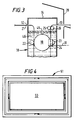
- the upper edge of the bleach tank ll is formed by an inwardly-curved tank wall portion 28 which helps to reduce the risk of bleach splashing out of the tank ll, since any bleach in that tank ll which was slopped upwards would tend to be deflected back into the tank ll by the inwardly curved wall portion 28 if it struck that wall portion 28.
- the mounting of the developer tank 10 above the bleach tank ll leads to a reduction in the chance of bleach splashing into the developer and contaminating it. That risk is further reduced by the use of the shields and the gate arrangement, and also by the use of floating covers 45 (see Figure 3) which are inserted through the open tops of the tanks so that they float on the top of the solution 46 in those tanks in order to minimise evaporation.
- a processing unit in which this invention is embodied is suitable for use when mounted on a mobile platform such as in a ship, a plane, a train or a lorry where there is a risk of splashing of the chemical solution in the tanks.
- Figure 4 shows such a unit 50 mounted in a gimbal frame 51 on such a moving platform in order to reduce the risk of splashing.
- the unit is mounted on a vehicle, such as a train, it would be expedient to arrange it with the developer tank 10 at the rear of the unit, in the sense of the forwards direction of travel so that, in the event of sudden braking solution would tend to surge up and splash away from the developer.
Landscapes
- Physics & Mathematics (AREA)
- General Physics & Mathematics (AREA)
- Photographic Processing Devices Using Wet Methods (AREA)
Applications Claiming Priority (2)
| Application Number | Priority Date | Filing Date | Title |
|---|---|---|---|
| GB9226175 | 1992-12-16 | ||
| GB929226175A GB9226175D0 (en) | 1992-12-16 | 1992-12-16 | Processing unit |
Publications (3)
| Publication Number | Publication Date |
|---|---|
| EP0602931A2 true EP0602931A2 (de) | 1994-06-22 |
| EP0602931A3 EP0602931A3 (de) | 1995-03-08 |
| EP0602931B1 EP0602931B1 (de) | 2000-05-03 |
Family
ID=10726673
Family Applications (1)
| Application Number | Title | Priority Date | Filing Date |
|---|---|---|---|
| EP93310064A Expired - Lifetime EP0602931B1 (de) | 1992-12-16 | 1993-12-14 | Entwicklungseinheit |
Country Status (4)
| Country | Link |
|---|---|
| US (1) | US5452042A (de) |
| EP (1) | EP0602931B1 (de) |
| DE (1) | DE69328539T2 (de) |
| GB (1) | GB9226175D0 (de) |
Families Citing this family (2)
| Publication number | Priority date | Publication date | Assignee | Title |
|---|---|---|---|---|
| US7617820B2 (en) * | 2004-06-15 | 2009-11-17 | Smart Parts, Inc. | Pneumatic paintball gun |
| US7657209B2 (en) * | 2007-09-24 | 2010-02-02 | Hewlett-Packard Development Company, L.P. | Apparatus for containing splashes in an ink developer |
Family Cites Families (9)
| Publication number | Priority date | Publication date | Assignee | Title |
|---|---|---|---|---|
| DE2445503B2 (de) * | 1974-09-24 | 1979-02-08 | Heinrich 6054 Rodgau Huss | Einrichtung zur Durchlaufentwicklung band- oder blattförmiger, fotografischer Schichtträger |
| JPH0142097Y2 (de) * | 1985-07-12 | 1989-12-11 | ||
| JPS63167362A (ja) * | 1986-12-27 | 1988-07-11 | Konica Corp | 銀塩感材用カラ−複写装置 |
| JP2767423B2 (ja) * | 1988-03-04 | 1998-06-18 | コニカ株式会社 | 均一濡れ構造の渡り搬送部を有する自動現像機 |
| JPH01302250A (ja) * | 1988-05-30 | 1989-12-06 | Minolta Camera Co Ltd | 現像機 |
| JPH0284642A (ja) * | 1988-06-17 | 1990-03-26 | Fuji Photo Film Co Ltd | 感光材料処理装置 |
| US4987438A (en) * | 1988-06-27 | 1991-01-22 | Konica Corporation | Apparatus for processing light-sensitive material |
| US5241336A (en) * | 1989-02-01 | 1993-08-31 | Eastman Kodak Company | Processing unit |
| DE69116666T2 (de) * | 1990-07-09 | 1996-06-13 | Fuji Photo Film Co Ltd | Vorrichtung zur verarbeitung von lichtempfindlichem silberhalogenidmaterial |
-
1992
- 1992-12-16 GB GB929226175A patent/GB9226175D0/en active Pending
-
1993
- 1993-12-13 US US08/166,114 patent/US5452042A/en not_active Expired - Fee Related
- 1993-12-14 EP EP93310064A patent/EP0602931B1/de not_active Expired - Lifetime
- 1993-12-14 DE DE69328539T patent/DE69328539T2/de not_active Expired - Fee Related
Also Published As
| Publication number | Publication date |
|---|---|
| US5452042A (en) | 1995-09-19 |
| EP0602931B1 (de) | 2000-05-03 |
| GB9226175D0 (en) | 1993-02-10 |
| DE69328539D1 (de) | 2000-06-08 |
| DE69328539T2 (de) | 2001-01-04 |
| EP0602931A3 (de) | 1995-03-08 |
Similar Documents
| Publication | Publication Date | Title |
|---|---|---|
| US4533225A (en) | Sensitive material processing apparatus | |
| US3699869A (en) | Film processing apparatus for processing films of different type | |
| EP0602931B1 (de) | Entwicklungseinheit | |
| US5070351A (en) | Method and apparatus for processing photosensitive material | |
| US3589263A (en) | Photographic processing apparatus | |
| US4362377A (en) | Film processor with agitation means | |
| DE3329966A1 (de) | Vorrichtung zum entwickeln von filmscheiben | |
| US5493360A (en) | Film processor | |
| US5400104A (en) | Photographic processing apparatus | |
| US3595156A (en) | Equipment for developing photographic film | |
| JPH01302250A (ja) | 現像機 | |
| JPS60194455A (ja) | 現像装置用エアレ−シヨン装置 | |
| EP0581543B1 (de) | Photographisches Entwicklungsgerät mit zwei Filmbeförderungsgeschwindigkeiten | |
| JPH0844034A (ja) | 現像処理装置 | |
| JPH0210521Y2 (de) | ||
| JP3725674B2 (ja) | 感光材料処理液補充装置 | |
| JPH05265226A (ja) | 感光材料処理装置の処理液補充装置 | |
| JP3671655B2 (ja) | 自動現像機 | |
| JPH0233145A (ja) | エアレーション装置及びこのエアレーション装置を備える自動現像機 | |
| JPH103156A (ja) | 現像処理装置の補充液撹拌装置 | |
| EP0919866A1 (de) | Vorrichtung und Verfahren zur Behandlung von photographischem Blattmaterial | |
| JP3192463B2 (ja) | 補水機能付現像処理装置 | |
| JP3529564B2 (ja) | 処理剤補給装置 | |
| JPH1090856A (ja) | 現像処理装置 | |
| WO1993014442A1 (en) | Photographic processing apparatus |
Legal Events
| Date | Code | Title | Description |
|---|---|---|---|
| PUAI | Public reference made under article 153(3) epc to a published international application that has entered the european phase |
Free format text: ORIGINAL CODE: 0009012 |
|
| AK | Designated contracting states |
Kind code of ref document: A2 Designated state(s): DE FR GB IT |
|
| PUAL | Search report despatched |
Free format text: ORIGINAL CODE: 0009013 |
|
| AK | Designated contracting states |
Kind code of ref document: A3 Designated state(s): DE FR GB IT |
|
| 17P | Request for examination filed |
Effective date: 19950818 |
|
| 17Q | First examination report despatched |
Effective date: 19980512 |
|
| GRAG | Despatch of communication of intention to grant |
Free format text: ORIGINAL CODE: EPIDOS AGRA |
|
| GRAG | Despatch of communication of intention to grant |
Free format text: ORIGINAL CODE: EPIDOS AGRA |
|
| GRAH | Despatch of communication of intention to grant a patent |
Free format text: ORIGINAL CODE: EPIDOS IGRA |
|
| GRAH | Despatch of communication of intention to grant a patent |
Free format text: ORIGINAL CODE: EPIDOS IGRA |
|
| GRAH | Despatch of communication of intention to grant a patent |
Free format text: ORIGINAL CODE: EPIDOS IGRA |
|
| GRAA | (expected) grant |
Free format text: ORIGINAL CODE: 0009210 |
|
| ITF | It: translation for a ep patent filed | ||
| AK | Designated contracting states |
Kind code of ref document: B1 Designated state(s): DE FR GB IT |
|
| REF | Corresponds to: |
Ref document number: 69328539 Country of ref document: DE Date of ref document: 20000608 |
|
| ET | Fr: translation filed | ||
| REG | Reference to a national code |
Ref country code: GB Ref legal event code: 732E |
|
| PLBE | No opposition filed within time limit |
Free format text: ORIGINAL CODE: 0009261 |
|
| STAA | Information on the status of an ep patent application or granted ep patent |
Free format text: STATUS: NO OPPOSITION FILED WITHIN TIME LIMIT |
|
| 26N | No opposition filed | ||
| PGFP | Annual fee paid to national office [announced via postgrant information from national office to epo] |
Ref country code: FR Payment date: 20011203 Year of fee payment: 9 |
|
| PGFP | Annual fee paid to national office [announced via postgrant information from national office to epo] |
Ref country code: DE Payment date: 20011228 Year of fee payment: 9 |
|
| REG | Reference to a national code |
Ref country code: GB Ref legal event code: IF02 |
|
| PGFP | Annual fee paid to national office [announced via postgrant information from national office to epo] |
Ref country code: GB Payment date: 20021104 Year of fee payment: 10 |
|
| PG25 | Lapsed in a contracting state [announced via postgrant information from national office to epo] |
Ref country code: DE Free format text: LAPSE BECAUSE OF NON-PAYMENT OF DUE FEES Effective date: 20030701 |
|
| PG25 | Lapsed in a contracting state [announced via postgrant information from national office to epo] |
Ref country code: FR Free format text: LAPSE BECAUSE OF NON-PAYMENT OF DUE FEES Effective date: 20030901 |
|
| REG | Reference to a national code |
Ref country code: FR Ref legal event code: ST |
|
| PG25 | Lapsed in a contracting state [announced via postgrant information from national office to epo] |
Ref country code: GB Free format text: LAPSE BECAUSE OF NON-PAYMENT OF DUE FEES Effective date: 20031214 |
|
| GBPC | Gb: european patent ceased through non-payment of renewal fee |
Effective date: 20031214 |
|
| PG25 | Lapsed in a contracting state [announced via postgrant information from national office to epo] |
Ref country code: IT Free format text: LAPSE BECAUSE OF NON-PAYMENT OF DUE FEES;WARNING: LAPSES OF ITALIAN PATENTS WITH EFFECTIVE DATE BEFORE 2007 MAY HAVE OCCURRED AT ANY TIME BEFORE 2007. THE CORRECT EFFECTIVE DATE MAY BE DIFFERENT FROM THE ONE RECORDED. Effective date: 20051214 |