EP0603810B1 - Dispositif d'éclairage pour véhicule - Google Patents
Dispositif d'éclairage pour véhicule Download PDFInfo
- Publication number
- EP0603810B1 EP0603810B1 EP93120570A EP93120570A EP0603810B1 EP 0603810 B1 EP0603810 B1 EP 0603810B1 EP 93120570 A EP93120570 A EP 93120570A EP 93120570 A EP93120570 A EP 93120570A EP 0603810 B1 EP0603810 B1 EP 0603810B1
- Authority
- EP
- European Patent Office
- Prior art keywords
- lighting device
- wall surface
- lens
- vehicle
- hand
- Prior art date
- Legal status (The legal status is an assumption and is not a legal conclusion. Google has not performed a legal analysis and makes no representation as to the accuracy of the status listed.)
- Expired - Lifetime
Links
Images
Classifications
-
- B—PERFORMING OPERATIONS; TRANSPORTING
- B60—VEHICLES IN GENERAL
- B60Q—ARRANGEMENT OF SIGNALLING OR LIGHTING DEVICES, THE MOUNTING OR SUPPORTING THEREOF OR CIRCUITS THEREFOR, FOR VEHICLES IN GENERAL
- B60Q1/00—Arrangement of optical signalling or lighting devices, the mounting or supporting thereof or circuits therefor
- B60Q1/26—Arrangement of optical signalling or lighting devices, the mounting or supporting thereof or circuits therefor the devices being primarily intended to indicate the vehicle, or parts thereof, or to give signals, to other traffic
- B60Q1/28—Arrangement of optical signalling or lighting devices, the mounting or supporting thereof or circuits therefor the devices being primarily intended to indicate the vehicle, or parts thereof, or to give signals, to other traffic for indicating front of vehicle
Definitions
- the present invention relates generally to a lighting device for a vehicle. More particularly, the present invention relates to improvement of a lighting device of the foregoing type which assures that appearance properties of the lighting device are not deteriorated.
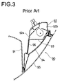
- a right-hand inner wall surface 92a of a housing 92 integrated with a device enclosure 91 for assembling, e.g., a headlamp thereon is dimensioned to have a length longer than that of a left-hand inner wall surface 92a so as to allow the contour of the housing 92 located at the front turn portion of a vehicle body to match with the contour of a corner portion of the vehicle body.
- an inner lens 93 is fitted to an opening portion of the housing 92 with an attitude orienting at a substantially right angle relative to the direction of running of the vehicle mainly for the purpose of determining light distribution properties of the lighting device 90.
- an outer lens 94 is disposed outside of the inner lens 93 while extending in conformity with the contour of the vehicle body.
- a transparent colorless material is employed for molding the outer lens 94.
- the color of the light beam generated by the lighting device 90 is determined by a transparent colored material employed for molding the inner lens 93.
- reference numeral 95 designates a transparent colorless cover lens mounted on the vehicle body in such a manner as to allow the whole device enclosure 91 to be covered therewith so as to improve the aesthetic appearance of the integrated structure composed of the headlamp and the lighting device 90.
- the lighting device 90 conventionally constructed in the above-described manner, since the transparent colorless material is employed for the outer lens 93, the presence of a part of the right-hand inner wall surface 92a between the inner lens 93 and the outer lens 94 can visually be recognized through the outer lens 93 from the outside. To assure that anybody does not feel some uneasiness due to the presence of the colorless surface area at the time of the foregoing visual recognizing, a measure is taken such that the right-hand inner wall surface 92a is lined with a film of vacuum-deposited aluminum or paint to form a reflective surface 96 so as to improve the appearance properties of the lighting device 90.
- the reflective surface 96 is formed only on a small part of the right-hand inner wall surface 92a in the vicinity of the device enclosure 91 including a housing of other lighting device such as a headlamp, a fog lamp or the like, it is necessary that the remaining part of the lighting device 90 exclusive of the reflective surface 96 is masked with a certain material so as not allow it to be lined with a film of vacuum-deposited aluminum or paint.
- the masking step requires many manhours, and moreover, each masking operation is performed in a complicated manner.
- the device enclosure 91 has a large surface area, a large quantity of gas is generated during the vacuum-depositing operation, and moreover, a long time is taken as an idling time until a high degree of vacuum enough to perform each vacuum-depositing operation is reached. Consequently, the lighting device 90 is unavoidably fabricated at a low efficiency.
- US-A-4,849,861 discloses a different type of a lighting device in which the inner lens is colorless whereas the outer lens is red and the inner lens has an extension forming a reflector and being arranged at an acute angle above a horizontal partition wall surface of the lighting device.
- the present invention has been made in consideration of the aforementioned background.
- An object of the present invention is to provide a lighting device for a vehicle which assures that there does not arise a malfunction that appearance properties of the lighting device are deteriorated due to the presence of a colorless surface area visually recognizable from the outside.
- Another object of the present invention is to provide a lighting device of the foregoing type which can be fabricated at an inexpensive cost.
- the present invention provides a lighting device for a vehicle including a housing designed to have a configure coincident with that of the corner portion of a vehicle, a left-hand inner wall surface of the housing being dimensioned to have a length different from that of a right-hand inner wall surface of the same, an inner lens molded of a transparent colored material and fitted to an opening portion of the housing with an attitude orienting at a substantially right angle relative to the direction of running of the vehicle, and an outer lens molded of a transparent colorless material and disposed in conformity with the contour of a vehicle body, wherein the inner lens includes an extension portion which extends along one of the inner wall surfaces while coming in close contact with said wall surface, and the foremost end of the extension portion reaches a rear surface of the outer lens.
- all surfaces associated with the inner lens i.e., an inner wall surface, a lower inner wall surface and an upper inner wall surface are lined with said extension portion of said inner lens to form a surface layer on said wall surfaces.
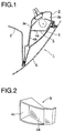
- Fig. 1 shows by way of sectional plan view the structure of a lighting device 1 for a vehicle constructed according to an embodiment of the present invention.
- the lighting device 1 is designed as part of a headlamp assembly and includes a housing 3 at the front turn portion of a vehicle body.
- the housing 3 of the lighting device 1 forms part of a device enclosure 2 integrated with a housing of other lighting device such as a headlamp, a fog lamp or the like (not shown).
- a right-hand inner wall surface 3a is dimensioned to have a length longer than that of a left-hand inner wall surface 3b in the same manner as the conventional lighting device 90 described above with reference to Fig. 3.
- a cover lens 6 is mounted on the lighting device 1 so as to allow the whole lighting device 1 to be covered therewith.
- an inner lens 4 molded of a transparent colored material and an outer lens 5 molded of a transparent colorless synthetic resin are fitted to an opening portion of the housing 3, whereby the presence of a right-hand inner wall surface 3a can visually be recognized by any one through the outer lens 5 from the outside in the same manner as the conventional lighting device 90.
- the inner lens 4 includes an extension portion 4b in addition to a lens portion 4a serving to determine light distribution properties of the lighting device 1. The arrangement of the extension portion 4b along the right-hand inner wall surface 3a makes it possible to prevent the presence of the right-hand inner wall surface 3a from being directly visually recognized by anyone through the outer lens 5 from the outside.
- the structure of the inner lens 4 will be described in more detail below.
- the lens portion 4a of the inner lens 4 is fitted to the opening portion of the housing 3 with an attitude orienting at a substantially right angle relative to the direction of running of the vehicle, i.e., the direction of irradiating of the light beam generated by the lighting device 1.
- the extension portion 4b of the inner lens 4 extends in the forward direction while coming in close contact with the right-hand wall surface 3a until the foremost end of the extension portion 4b reaches the rear surface of the outer lens 5.
- the whole area of the right-hand inner wall surface 3a is covered with the extension member 4b, whereby there does not arise a malfunction that anyone feels some uneasiness attributable to the presence of the colorless surface when he visually observes the right-hand wall surface 3a through the transparent colorless outer lens 5.
- the present invention has been described above with respect to the embodiment wherein the lighting device 1 is mounted on the left-hand side of the vehicle. Alternatively, the present invention may equally be applied to the case that it is mounted on the right-hand side of the vehicle.
- the extension portion 4c is disposed only along the right-hand inner wall surface 3a of the housing 3.
- an extension portion 4c is disposed in such a manner that all inner wall surfaces associated with an inner lens 4 , i.e., a left-hand inner wall surface 3a, a lower inner wall surface and an upper inner wall surface each visually recognizable through an outer lens 5 are lined with the extension portion 4c.
- the lighting device 1 has been described above with respect to the case that the housing 3 is disposed at a part of the device enclosure 2.
- the present invention may equally be applied to the case that the whole device enclosure 2 is constructed with the housing 1.
Landscapes
- Engineering & Computer Science (AREA)
- Mechanical Engineering (AREA)
- Non-Portable Lighting Devices Or Systems Thereof (AREA)
Claims (2)
- Dispositif d'éclairage pour un véhicule comprenant un carter (3) destiné à présenter une configuration coïncidant avec celle de la partie en coin d'une carrosserie de véhicule, une surface de paroi intérieure gauche (3a ou 3b) dudit carter (3) étant calibrée pour présenter une longueur différente de celle d'une surface de paroi intérieure droite (3b ou 3a) de celui-ci, une lentille intérieure (4) moulée dans un matériau de couleur transparent et adaptée à une partie d'ouverture dudit carter avec un positionnement s'orientant selon un angle sensiblement droit par rapport à la direction dans laquelle roule ledit véhicule, et une lentille extérieure (5) moulée dans un matériau non coloré transparent et disposée conformément au contour d'une carrosserie de véhicule, caractérisé en ce que ladite lentille intérieure comprend une partie en extension (4b) qui s'étend le long de l'une desdites surfaces de paroi intérieure gauche et droite tout en venant en contact intime avec ladite surface de paroi, et la partie la plus avancée de ladite partie en extension atteint une surface arrière de ladite lentille extérieure.
- Dispositif d'éclairage selon la revendication 1, dans lequel toutes les surfaces associées à ladite lentille intérieure (4), c'est-à-dire une desdites surfaces intérieures, une surface de paroi intérieure inférieure et une surface de paroi intérieure supérieure sont recouvertes par ladite partie en extension (4c) de ladite lentille intérieure (4) pour former une couche de surface sur lesdites surfaces de paroi.
Applications Claiming Priority (2)
| Application Number | Priority Date | Filing Date | Title |
|---|---|---|---|
| JP92114/92 | 1992-12-21 | ||
| JP1992092114U JPH0735211Y2 (ja) | 1992-12-21 | 1992-12-21 | 車両用灯具 |
Publications (2)
| Publication Number | Publication Date |
|---|---|
| EP0603810A1 EP0603810A1 (fr) | 1994-06-29 |
| EP0603810B1 true EP0603810B1 (fr) | 1997-03-26 |
Family
ID=14045412
Family Applications (1)
| Application Number | Title | Priority Date | Filing Date |
|---|---|---|---|
| EP93120570A Expired - Lifetime EP0603810B1 (fr) | 1992-12-21 | 1993-12-21 | Dispositif d'éclairage pour véhicule |
Country Status (4)
| Country | Link |
|---|---|
| US (1) | US5398172A (fr) |
| EP (1) | EP0603810B1 (fr) |
| JP (1) | JPH0735211Y2 (fr) |
| DE (1) | DE69309241T2 (fr) |
Cited By (1)
| Publication number | Priority date | Publication date | Assignee | Title |
|---|---|---|---|---|
| DE19950700A1 (de) * | 1999-10-21 | 2001-04-26 | Volkswagen Ag | Heckleuchte mit Farbscheibe |
Families Citing this family (11)
| Publication number | Priority date | Publication date | Assignee | Title |
|---|---|---|---|---|
| JP2787415B2 (ja) * | 1994-03-28 | 1998-08-20 | 株式会社小糸製作所 | 車輌用標識灯 |
| DE19507585C2 (de) * | 1995-03-04 | 2002-04-18 | Bosch Gmbh Robert | Scheinwerfer-Leuchten-Einheit für Fahrzeuge |
| DE19519655B4 (de) * | 1995-05-30 | 2010-04-08 | Automotive Lighting Reutlingen Gmbh | An einem Frontteil eines Fahrzeugs angeordnete Beleuchtungseinrichtung |
| US6502974B2 (en) | 1999-02-18 | 2003-01-07 | Lacks Enterprises, Inc. | Integrated flexible lamp assembly |
| US6331068B1 (en) | 1999-02-18 | 2001-12-18 | Lacks Industries, Inc. | Flexible lamp mounting |
| US6190030B1 (en) | 1999-02-18 | 2001-02-20 | Lacks Industries, Inc. | Flexible lamp mounting |
| DE19950698B4 (de) * | 1999-10-21 | 2010-06-02 | Volkswagen Ag | Leuchte mit zwei Lichtscheiben |
| JP3961737B2 (ja) | 2000-02-29 | 2007-08-22 | 株式会社小糸製作所 | 車両用灯具およびその製造方法 |
| JP3913435B2 (ja) * | 2000-02-29 | 2007-05-09 | 株式会社小糸製作所 | 車両用灯具の製造方法 |
| DE102005007862A1 (de) * | 2005-02-21 | 2006-08-24 | General Motors Global Technology Operations, Inc., Detroit | Leuchtenanrordnung |
| FR2932435B1 (fr) * | 2008-06-17 | 2010-11-05 | Peugeot Citroen Automobiles Sa | Projecteur de vehicule automobile avec element de masquage de la solidarisation entre la glace et le boitier de ce projecteur |
Family Cites Families (8)
| Publication number | Priority date | Publication date | Assignee | Title |
|---|---|---|---|---|
| GB8327529D0 (en) * | 1983-10-14 | 1983-11-16 | Lucas Ind Plc | Indiscernible lamp |
| US4912606A (en) * | 1987-10-28 | 1990-03-27 | Koito Manufacturing Co., Ltd. | Vehicle lamp device |
| JPH01175538A (ja) * | 1987-12-28 | 1989-07-12 | Koito Mfg Co Ltd | 自動車用ハイマウンテッドストップランプ |
| JPH01235101A (ja) * | 1988-03-16 | 1989-09-20 | Koito Mfg Co Ltd | 車輌用灯具 |
| JPH0664926B2 (ja) * | 1988-06-30 | 1994-08-22 | 市光工業株式会社 | 車両用灯具 |
| US5006966A (en) * | 1989-08-30 | 1991-04-09 | Transmatic, Inc. | Transit vehicle lighting fixture |
| JPH0740443B2 (ja) * | 1990-03-15 | 1995-05-01 | 株式会社小糸製作所 | 自動車用ターンシグナルランプ |
| US5287101A (en) * | 1990-03-15 | 1994-02-15 | Koito Manufacturing Co., Ltd. | Vehicular turn signal lamp |
-
1992
- 1992-12-21 JP JP1992092114U patent/JPH0735211Y2/ja not_active Expired - Lifetime
-
1993
- 1993-12-13 US US08/166,510 patent/US5398172A/en not_active Expired - Fee Related
- 1993-12-21 EP EP93120570A patent/EP0603810B1/fr not_active Expired - Lifetime
- 1993-12-21 DE DE69309241T patent/DE69309241T2/de not_active Expired - Fee Related
Cited By (1)
| Publication number | Priority date | Publication date | Assignee | Title |
|---|---|---|---|---|
| DE19950700A1 (de) * | 1999-10-21 | 2001-04-26 | Volkswagen Ag | Heckleuchte mit Farbscheibe |
Also Published As
| Publication number | Publication date |
|---|---|
| DE69309241D1 (de) | 1997-04-30 |
| US5398172A (en) | 1995-03-14 |
| JPH0735211Y2 (ja) | 1995-08-09 |
| JPH0654118U (ja) | 1994-07-22 |
| EP0603810A1 (fr) | 1994-06-29 |
| DE69309241T2 (de) | 1997-07-17 |
Similar Documents
| Publication | Publication Date | Title |
|---|---|---|
| US5287101A (en) | Vehicular turn signal lamp | |
| EP0603810B1 (fr) | Dispositif d'éclairage pour véhicule | |
| JPS62165802A (ja) | 車両用二重目的信号ランプ | |
| JPH10125113A (ja) | 車輌用灯具 | |
| US5373423A (en) | Light for motor vehicle | |
| EP0922903B1 (fr) | Feu multifonction arrière pour véhicule | |
| US4041302A (en) | Dual color taillamp | |
| JPH0685281B2 (ja) | ランプ一体型フロントグリル | |
| US6050706A (en) | Vehicle turn signal lamp having light bulb covered with transparent cap and transparent lens for enhancing vehicle lamp appearance | |
| GB2242014A (en) | Vehicular signal lamp | |
| JP3360518B2 (ja) | 車両用灯具 | |
| JPH083928Y2 (ja) | マークプレートランプ | |
| JPH0323607Y2 (fr) | ||
| JPH0766684B2 (ja) | 自動車用前照灯 | |
| JPH0113283Y2 (fr) | ||
| JPH0724722Y2 (ja) | 車両用信号灯具のレンズ構造 | |
| JPH0127208Y2 (fr) | ||
| JP2599123Y2 (ja) | 車輌用灯具 | |
| JP2600642Y2 (ja) | 自動車用標識灯 | |
| JP2599850Y2 (ja) | 車両用灯具 | |
| JP2573151Y2 (ja) | 車両用灯具 | |
| JP2592672Y2 (ja) | 車両用灯具 | |
| JPH0346403Y2 (fr) | ||
| JPH081523Y2 (ja) | 車両用灯具 | |
| JPH0711361Y2 (ja) | 車両用灯具 |
Legal Events
| Date | Code | Title | Description |
|---|---|---|---|
| PUAI | Public reference made under article 153(3) epc to a published international application that has entered the european phase |
Free format text: ORIGINAL CODE: 0009012 |
|
| AK | Designated contracting states |
Kind code of ref document: A1 Designated state(s): DE FR GB |
|
| 17P | Request for examination filed |
Effective date: 19940901 |
|
| 17Q | First examination report despatched |
Effective date: 19950919 |
|
| GRAG | Despatch of communication of intention to grant |
Free format text: ORIGINAL CODE: EPIDOS AGRA |
|
| GRAH | Despatch of communication of intention to grant a patent |
Free format text: ORIGINAL CODE: EPIDOS IGRA |
|
| GRAH | Despatch of communication of intention to grant a patent |
Free format text: ORIGINAL CODE: EPIDOS IGRA |
|
| GRAA | (expected) grant |
Free format text: ORIGINAL CODE: 0009210 |
|
| AK | Designated contracting states |
Kind code of ref document: B1 Designated state(s): DE FR GB |
|
| REF | Corresponds to: |
Ref document number: 69309241 Country of ref document: DE Date of ref document: 19970430 |
|
| ET | Fr: translation filed | ||
| PLBE | No opposition filed within time limit |
Free format text: ORIGINAL CODE: 0009261 |
|
| STAA | Information on the status of an ep patent application or granted ep patent |
Free format text: STATUS: NO OPPOSITION FILED WITHIN TIME LIMIT |
|
| 26N | No opposition filed | ||
| PGFP | Annual fee paid to national office [announced via postgrant information from national office to epo] |
Ref country code: DE Payment date: 19981205 Year of fee payment: 6 |
|
| PGFP | Annual fee paid to national office [announced via postgrant information from national office to epo] |
Ref country code: GB Payment date: 19981215 Year of fee payment: 6 |
|
| PGFP | Annual fee paid to national office [announced via postgrant information from national office to epo] |
Ref country code: FR Payment date: 19981224 Year of fee payment: 6 |
|
| PG25 | Lapsed in a contracting state [announced via postgrant information from national office to epo] |
Ref country code: GB Free format text: LAPSE BECAUSE OF NON-PAYMENT OF DUE FEES Effective date: 19991221 |
|
| GBPC | Gb: european patent ceased through non-payment of renewal fee |
Effective date: 19991221 |
|
| PG25 | Lapsed in a contracting state [announced via postgrant information from national office to epo] |
Ref country code: FR Free format text: LAPSE BECAUSE OF NON-PAYMENT OF DUE FEES Effective date: 20000831 |
|
| PG25 | Lapsed in a contracting state [announced via postgrant information from national office to epo] |
Ref country code: DE Free format text: LAPSE BECAUSE OF NON-PAYMENT OF DUE FEES Effective date: 20001003 |
|
| REG | Reference to a national code |
Ref country code: FR Ref legal event code: ST |