EP0604899B1 - Système de support pour baignoire ou cuve de douche - Google Patents
Système de support pour baignoire ou cuve de douche Download PDFInfo
- Publication number
- EP0604899B1 EP0604899B1 EP93120735A EP93120735A EP0604899B1 EP 0604899 B1 EP0604899 B1 EP 0604899B1 EP 93120735 A EP93120735 A EP 93120735A EP 93120735 A EP93120735 A EP 93120735A EP 0604899 B1 EP0604899 B1 EP 0604899B1
- Authority
- EP
- European Patent Office
- Prior art keywords
- baseplate
- tub
- carrier system
- accordance
- sidewalls
- Prior art date
- Legal status (The legal status is an assumption and is not a legal conclusion. Google has not performed a legal analysis and makes no representation as to the accuracy of the status listed.)
- Expired - Lifetime
Links
Images







Classifications
-
- A—HUMAN NECESSITIES
- A47—FURNITURE; DOMESTIC ARTICLES OR APPLIANCES; COFFEE MILLS; SPICE MILLS; SUCTION CLEANERS IN GENERAL
- A47K—SANITARY EQUIPMENT; ACCESSORIES THEREFOR, e.g. TOILET ACCESSORIES
- A47K3/00—Baths; Showers; Appurtenances therefor
- A47K3/008—Sealing between wall and bathtub or shower tray
-
- A—HUMAN NECESSITIES
- A47—FURNITURE; DOMESTIC ARTICLES OR APPLIANCES; COFFEE MILLS; SPICE MILLS; SUCTION CLEANERS IN GENERAL
- A47K—SANITARY EQUIPMENT; ACCESSORIES THEREFOR, e.g. TOILET ACCESSORIES
- A47K3/00—Baths; Showers; Appurtenances therefor
- A47K3/02—Baths
-
- A—HUMAN NECESSITIES
- A47—FURNITURE; DOMESTIC ARTICLES OR APPLIANCES; COFFEE MILLS; SPICE MILLS; SUCTION CLEANERS IN GENERAL
- A47K—SANITARY EQUIPMENT; ACCESSORIES THEREFOR, e.g. TOILET ACCESSORIES
- A47K3/00—Baths; Showers; Appurtenances therefor
- A47K3/16—Devices for fastening baths to floors or walls; Adjustable bath feet ; Lining panels or attachments therefor
Definitions
- the invention relates to a support system for a bath or shower tray according to the preamble of claim 1.
- Such a carrier system is known from FR-A-2 451 736.
- this consists of a holding frame with an essentially rectangular cross-section, which comprises vertical side walls and a border which is arranged at the upper region of the side walls and extends inward approximately perpendicularly to these.
- the side walls are provided with horizontal reinforcement ribs.
- this known holding frame either does not have its own floor, in which case beams running perpendicular to the side walls can be provided, which form a support for the respective trough, or is provided with a floor formed in one piece with the side walls.
- At least the side walls of this known holding frame can consist of cell-like polystyrene and can be clad at least on the outside with glass fiber reinforced plastic.
- the object of the invention is therefore to provide a carrier system for bathtubs or shower trays which is extremely easy to handle and can be assembled properly without special technical knowledge and thereby ensures that disruptive structure-borne noise transmissions are inevitably ruled out and thus a proper and the existing provisions and recognized rules of Appropriate tub installation is guaranteed.
- This basic concept creates a bathtub receptacle to be attached or assembled at the respective installation site of the bathtub, which provides sound decoupling from the structure at least with regard to the critical bathtub edges while ensuring simple tub installation and precludes any structure-borne noise bridge. If this support system is installed on a functional screed that is at least acoustically adequate for the sound-absorbing sandwich floor slab, then the thermal and impact sound insulation located below the screed layer can also take over the structure-borne sound insulation of the tub, and the floor slab of the support system can function as normal , uninsulated panel.
- a sound-absorbing sandwich panel designed analogously to the side walls is used as the base plate, so that in this case the acoustic decoupling of the respective tub from the structure is completely taken over by the support system.
- the layer representing the outer planking is mechanically firm and preferably moisture-resistant.
- the inner layer, against which the tub rim rests after the tub has been installed, can also be mechanically strong or, if necessary, only consist of a mechanically weak top layer, the main task of which is to protect the actual insulation layer from damage.
- the carrier system is preferably designed so that the base plate with the side walls via plug connections, for. B. using U-profile receptacles, can be coupled, the corner areas can be mutually fixed via plug caps, latches and the like.
- the carrier system according to the invention is provided in a few dimensions which are adapted to fixed standard dimensions of the tubs.
- the support system it is also possible to adapt the support system to different tub sizes, in accordance with one embodiment variant of the invention providing the base plate and the side walls with predetermined breaking incisions adapted to the standard tub sizes, so that the appropriate system can be put together on site from standard basic elements without any problems can.
- this size adjustment can also take place in that a size-adjustable base plate is provided, the size adjustment being achieved in that the base plate is formed at least in two parts and the two parts are coupled to one another via telescopic organs.
- This base plate which is variable in size, can then be combined with the appropriate side walls, which in turn can be side walls which can be adapted to the respective application by reducing the size via predetermined breaking points.
- the adaptation and sealing of the carrier system with respect to the respective trough is preferably carried out via dome or end profile parts which can be plugged onto the upper free side wall ends and which can consist of an elastic material, but are preferably formed by a molded part which has a receptacle for inserting a sealing lip which in the assembled state under prestress on the tub rim.
- the profile part can be made of metal or plastic, or coated plastic material exist so that an aesthetically perfect and appealing appearance is obtained.
- the base plate comprises at least one inner layer and a layer of soft resilient material arranged underneath and that at least the central region of the inner layer of the base plate intended for tub support is separated from the edge region of the inner layer and acoustically decoupled.
- the inner layer of the central region which consists in particular of a moisture-resistant material, and the edge region of the inner layer are preferably arranged on a common layer of soft-resilient material and connected to this layer.
- This design of the base plate creates an acoustically decoupled central area, which takes over the main support function for the tub, while the edge area serves to support the side walls, which, according to special configurations, can also take on the function of tub edge support.
- the base plate is preferably designed in a sandwich construction, wherein adjustable or exchangeable support members can be provided on the mechanically stable outer paneling for adjusting the base plate.
- adjustable or exchangeable support members support blocks of different dimensions can be inserted into corresponding recesses, while in the case of adjustable support members, organs that can be adjusted can be held in the sturdy outer planking by means of a screw adjustment.
- the base plate and / or the side walls can each be designed in several parts in order to adapt to different tub sizes, the various parts being connected to one another via clampable sliding guides which lie on the inside to be attached to the outer paneling.
- the mutual connection of the side walls to create a stable box frame that can be supported on the base plate is preferably carried out by means of self-wedging coupling elements fastened to the inner panel areas on the outer paneling, these coupling elements preferably comprising an angled part attached to a side wall with a coupling slot and a clamping engagement in the coupling slot , there are wedge hook parts attached to the other side wall.
- these side walls are designed to be height-adjustable with respect to the base plate, this height adjustment being able to be carried out using screw spindles which are supported in positioning receptacles of the base plate.
- these adjustable support rods are integrated in the coupling elements for connecting the side walls.
- the edge of the respective tub is supported at least in regions on the inner paneling of the side walls, this inner paneling in turn being preferably supported on the central region of the base plate, so that there is optimal acoustic decoupling and yet the tub edges are without the risk of Deflection can also be heavily loaded by the tub user.
- the inner paneling of the side walls is either provided with a telescopically height-adjustable support wall or there are height-adjustable, Support blocks forming tub edge supports are provided.
- Figure 1 shows a very simplified representation of the basic principle of the support system according to the invention, consisting of a base plate 1 and connected to this base plate 1 side walls 2, 3, so that a box structure with a receiving space 4 for the respective tub is created.
- This structure is adapted to the size of the tub to be accommodated.
- FIG. 2 shows a cross-sectional view through a support system according to the invention, this system being provided for mounting on a raw concrete ceiling, since the floor slab 1 has an insulation function.
- the side walls 2, 3 of the support system according to the invention are always constructed in sandwich construction and consist of a mechanically stable outer paneling 7 and one of them spaced inner layer 8, which can be made much less stable than the outer layer 7, as well as a completely or partially filling the space between the two layers 7, 8 soft spring material 5, z.
- the base plate 1 is designed at least for the case of mounting the support system on a raw concrete ceiling analogous to the side walls 2, 3, but has a mechanically stable inner layer 6 in order to be able to absorb the forces exerted by the trough properly.
- a normal, insulation-free plate can be used as base plate 1, since structure-borne noise insulation downwards is not required in this case.
- the use of a single-layer base plate offers the advantage of a lower overall height and of course also reduces the costs of the support system.
- the side walls 2, 3 are divided to facilitate storage and transport, so that partial side walls 2a, 2b are formed, which are connected to one another via hinges 9, which are arranged at different heights with respect to the individual side walls are. In this way, it is possible to fold down the side wall parts located at the top towards the bottom plate 1 and to obtain a small-volume stacking arrangement.
- An adaptation of the support system to the respective tub size can be made by appropriate selection of the sizes of the base plate 1 and the side walls 2 and 3, it being possible to provide basic designs of maximum size and to provide predetermined breaking incisions in the corresponding plates, so that on the construction site the corresponding The size can be adjusted if you do not know at the time of ordering the carrier system for which specific tub size this system is intended.
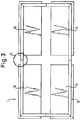
- Figure 3 shows an embodiment in which the different size requirements can be taken into account by a variable base plate 1.
- this base plate is divided into the longitudinal and transverse directions, so that four partial base plates 1a, 1b, 1c, 1d, preferably of the same size, are formed.
- These partial floor panels are connected to one another via a telescopic frame 10, i. H. over a frame that can be pulled apart in the longitudinal direction and / or in the transverse direction according to the respective requirements.
- individual telescopic members can also be arranged between the partial floor panels.
- a frame 10 provided in the outer circumferential area of the base plate 1 it can preferably be designed in the form shown in FIG. 4, since in this embodiment the telescopic frame simultaneously takes over the coupling function between the base plate 1 and the side walls 2, 3.
- Figure 4 shows the detail X from Figure 3 and shows that the telescopic frame 10 connected to the base plate 1 consists of a hollow profile 11 and a positively engaging rail 12 in this hollow profile, both the hollow profile 11 and the rail 12 with lateral vertical walls 13 are provided, are created by the U-profile receptacles for the side walls 2, 3.
- a further embodiment of the invention reduced to its minimally required components, can be used if the floating screed fully meets the requirements for structure-borne noise, since in in this case, the use of any base plate in connection with the support system can be dispensed with.
- the schematic representation according to FIG. 5 shows the arrangement of the support system receiving a tub edge 15 in front of a tiled wall.
- a profile part 14 with a lip 16 sealingly resting on the edge 15 of the tub is placed on the free upper side wall ends.
- the tub 15 lies with its edge 15 on the insulating material layer made of soft spring material 5 of the side wall, or on the corresponding inner planking or inner protective layer of this side wall, which is not specifically shown in FIG. 5, and it is readily apparent that due to this by the support system guaranteed connection technology between the tub edge 15 and the wall no structure-borne noise transmission can take place.
- the design of the profile part 14 is possible in various ways.
- this profile part can consist of elastic material, so that profile part 14 and sealing lip 16 can be made of the same material.
- the profile part shown in Figure 5 can also be carried out according to an expedient embodiment such that, starting from the upper transverse wall of the profile part, a web located between the sealing lip 16 and the side wall extends downward and the tub edge comes to rest against this web.
- This embodiment is particularly suitable for such side walls that have a stable and resilient inner paneling have, in this case, a structure-borne noise is prevented by the web located between the inner paneling and the edge of the tub made of insulating material in the required manner.
- a profile part made of stable and possibly coated in the required manner plastic material or metal or another non-elastic material is used, this profile part then having a receptacle for fixing an elastic sealing lip, which ensures the seal against the tub edge.
- This profile part can optionally also have a receptacle for fixing an insulating web which extends in the area between the tub edge and the inner paneling of the side wall.
- a stable profile part can also be provided with a longitudinally extending dome that engages in a corresponding groove in the side wall.
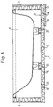
- FIG. 6 shows a conventional bathtub 20 which is supported on the base plate of a support system via support leg arrangements 21, the side walls 2 of which adjoin the respective tub edges and are flush with them.
- the base plate 1 consists of an inner layer 6 made of moisture-resistant material, which is arranged on a layer 5 made of soft resilient material or is connected to it.
- a stable outer paneling 7 can be provided on the underside, so that the z. B. from polystyrene, mineral wool, cork, coconut fibers or the like existing soft spring material between the inner layer 6 and the outer paneling 7 is included.
- the inner layer 6 of the base plate is divided into a central region 17 and an edge region 18, the central region 17 forming the actual tub support surface.
- the resulting between the central region 17 and the peripheral region 18 pronounced gap 19 is provided with air or with a gap filler 22, which consists, for example, of a closed-cell foam, the material used being Misselon (registered trademark of the applicant) with a tear-resistant surface.
- adjustable support members 23 are provided according to FIG. 7, which are accessible via recesses 24 in the inner layer and the soft-spring material 5. Since the outer paneling 7 is mechanically stable and preferably in the form of a hard plate, screw actuators can be fixed in this outer paneling 7 either directly or via inserted screw nuts, which enable stepless adjustment.
- hard foam blocks of different heights can also be inserted into corresponding recesses in the outer paneling instead of continuously adjustable adjusting members 23.
- FIG. 8 shows, in the form of a cutout, the connection of two partial side walls 2a, 2b via a clampable sliding guide 25.
- Two-part or multi-part side walls enable the carrier system to be easily adapted to different tub sizes, in which case correspondingly adjustable base plates are preferably also provided in connection with the adjustable side walls.
- the clampable sliding guide 25 consists of an open profile guide channel 26 and an elongated hole tab 27 which can be firmly connected to one another in different relative positions by means of a clamping screw 28.
- the profile guide channel 26 and the elongated hole tab 27 are fastened to the outer cladding of the respective side wall, ensure a stable connection of the partial side walls and enable the size of the respective side wall to be adjusted continuously.
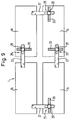
- FIG. 9 shows a base plate consisting of partial base plates 1a, 1b, 1c and 1d, which are connected to one another via clampable sliding guides 25 analogously to FIG. 8.
- the profile guide channels 26 and the respectively assigned elongated hole tabs 27 run perpendicular to one another, so that a continuous adjustment of the base plate in the direction of the length and the width is possible.
- the clamping screws 28 are easily accessible from the top of the base plate, so that the size adjustment can also be carried out without problems on the respective construction site.
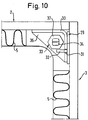
- FIG. 10 shows a preferred embodiment of coupling elements 29 for the current connection of side walls 2, 3.
- Each coupling element is formed by an angled part 30 fastened to a side wall, the free leg of which has a vertically running coupling slot 31, and by a fastened to the assigned second side wall Wedge hook part 32 which engages in the slot 31 and leads to a clamping lock between the two parts.
- a stable, non-positive and positive corner connection is created, which is very easy to implement and requires no tools or loose fastening parts.
- a transverse web 36 is integrated in the angle part 30.
- This crossbar 36 forms, together with a nut 37 welded to it, a support and guide element for a support rod 34 which extends in the vertical direction and is supported on the base plate.
- a support rod 34 which extends in the vertical direction and is supported on the base plate.
- FIG. 11 shows, in the form of a schematic partial sectional view, a specific embodiment of a side wall connection with an angled part 30 and a wedge hook part 32 extending over a substantial part of the side wall height, two superposed coupling points designed analogously to FIG. 10 being provided.
- the support rod 34 which is designed as a threaded spindle, extends through nuts 37 which are arranged coaxially and welded to transverse webs 36 and is supported in a positioning receptacle 35 on the edge region 18 of the base plate.
- the support rod 34 is easily accessible from above when the cover profile part 14 has not yet been attached and can, for. B. operated by a screwdriver, so that it is possible to make an exact height adjustment or adjustment of the side walls by means of the support rods 34 attached in the corner areas and to achieve that the outer paneling 7 of the side walls is exactly flush with the upper edge of the tub 20th lies and thus the cover profile part 14 can be attached correctly positioned, so that there is an exact and elegant connection between the tub edge and the profile part.
- FIG. 11 shows the installed state of the carrier system relative to a floor structure 40, the outer paneling 7 forming a carrier wall for a tiling 38 and the tiling just as the outer paneling 7 of the side wall is decoupled from the floor structure 40 in a sound-perfect manner.
- Figure 12 shows a side wall structure that allows support of the edge of the tub 20 and a z. B. has a wooden panel existing inner paneling 41, which extends between the central region 17 of the base plate and the underside of the tub edge and supports this tub edge directly, so that in the case of loads from tub users no undesirable deflection of the tub edge can occur.
- the insulating material provided between the inner paneling 41 and the outer paneling 7 preferably has a recess 51 in the tub edge area, in which the outer, downwardly bent part of the tub edge is preferably received in a form-fitting manner.
- FIG. 13 shows a further embodiment variant of a tub edge support, in which the inner paneling 41 has a telescopically height-adjustable support wall 45, which can be adjusted, for example, via an angular screw mechanism 46.
- a telescopically height-adjustable support wall 45 which can be adjusted, for example, via an angular screw mechanism 46.
- the side wall extends into the cavity formed by the tub rim, so that the tub rim is a visible element and the tiling can begin a short distance below the tub rim and can be arranged flush with the outside tub rim or indented.
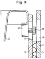
- FIG. 14 shows a further variant of a tub edge support, in this case, on the inside of the inner cladding 41, height-adjustable and externally clampable support blocks 49 are provided via elongated holes 47, which can be fixed at the required height by means of clamping screws 50. These clamping screws 50 are accessible via corresponding elongated holes 48 in the outer paneling 7, but are no longer visible after the outer paneling has been tiled.
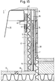
- FIG. 15 shows, in the form of a schematic illustration, a partially sectioned sectional illustration of a variant of the invention that has an optimal adjustment and setting option.
- the support rods 34 provided for height adjustment of the side walls no longer have to be arranged in the corner areas, but rather are integrated directly into the outer paneling 7 of the side walls, which are provided with through holes 39 for this purpose.
- a nut 44 is preferably integrated on the bottom, with which the respective threaded rod 34 is screwed.
- the support rods 34 are supported on the edge region 18 decoupled from the central region 17 of the base plate.
- the support rods 34 are accessible from above, so that the height adjustment can be done very simply by means of a screwdriver.
- the tub edge support is realized in this embodiment via support blocks 49 which are arranged in vertical bores 42 of the inner paneling 41 of the side walls. By turning this screw spindle 43, which in turn is easily accessible from above, the required height adjustment of the support block 49 can take place.
- This profile cover is preferably formed in the form of a composite system, i. H. it consists of a soft inner layer, which ensures acoustic decoupling, and a comparatively hard and also sturdy outer layer, which can be adapted or contrasted with regard to the color of the tub.
- the carrier system according to the invention despite the simple structure with regard to the required structure-borne sound insulation, yields optimal results, is extremely simple in construction and can be assembled and also ensures problem-free size adaptation to the respective tub.
Landscapes
- Health & Medical Sciences (AREA)
- Public Health (AREA)
- Epidemiology (AREA)
- General Health & Medical Sciences (AREA)
- Devices For Medical Bathing And Washing (AREA)
- Catalysts (AREA)
- Finishing Walls (AREA)
- Floor Finish (AREA)
Claims (22)
- Système de support pour baignoire ou bac à douche, dont les dimensions coïncident avec les dimensions de chaque type de baignoire,
caractérisé en ce qu'il se compose d'une ou plusieurs plaques de fond (1) formant une surface de support pour baignoire et de parois latérales (2, 3) qui peuvent être reliées ou assemblées à la plaque de fond (1), dans lequel au moins les parois latérales sont exécutées dans une structure en sandwich et l'espace entre deux parois écartées l'une de l'autre est rempli totalement ou partiellement d'un matériau antivibratoire souple (5) et en particulier dans le cas d'un montage sur une dalle brute en béton, la plaque de fond (1) est exécutée dans une structure en sandwich analogue à celle des parois latérales (2, 3) et dans le cas d'un montage sur une chape flottante la plaque de fond (1) utilisée est réalisée dans un matériau non isolant. - Système de support selon la revendication 1,
caractérisé en ce que les parois latérales (2, 3) sont assemblées aux petits côtés de la plaque de fond (1) ou reposent sur la zone de bordure de la plaque de fond (1) à laquelle elles peuvent être assemblées par des assemblages enfichables, en particulier par l'intermédiaire de profilés d'encastrement ou de guidage fixés à demeure sur la plaque de fond, les parois latérales (2, 3) étant de préférence munies de points destinés à la rupture ou d'entailles destinées à la rupture, afin de les adapter aux dimensions standards des baignoires. - Système de support selon l'une quelconque des revendications précédentes,
caractérisé en ce que les parois latérales (2, 3) sont assemblées à la plaque de fond (1) par des charnières pivotantes et sont, de préférence, divisées dans le sens longitudinal en différentes hauteurs, en ce que les deux parties sont reliées l'une à l'autre par des charnières rabattantes (9) et en ce que la position en hauteur des charnières rabattantes (9) est choisie de telle sorte que les parois latérales partielles rabattables (2a, 2b) sont empilées les unes sur les autres en position rabattue sur la plaque de fond (1). - Système de support selon l'une quelconque des revendications précédentes,
caractérisé en ce que les parois latérales contiguës (2, 3) sont assemblées, en particulier, par l'intermédiaire de cornières enfichables et/ou d'organes de verrouillage par serrage et en ce que, en particulier, la plaque de fond (1) est réalisée en deux parties qui sont assemblées l'une à l'autre par des organes télescopiques. - Système de support selon l'une quelconque des revendications précédentes,
caractérisé en ce que la plaque de fond (1) est partagée en sens long et en sens large pour former quatre plaques de fond partielles (1a, 1b, 1c, 1d) et en ce que les plaques de fond partielles (1a, 1b, 1c, 1d) sont assemblées les unes aux autres par des organes télescopiques et sont réglables en sens long et en sens large pour former des surfaces de plaques de fond différentes, les organes télescopiques étant de préférence assemblés pour former un cadre (10). - Système de support selon l'une quelconque des revendications précédentes,
caractérisé en ce que le cadre (10), télescopique dans un sens au moins, est monté dans la zone de bordure de la plaque de fond (1) et comprend des profilés creux rectangulaires (11), ainsi que des pièces de guidage (12) qui s'engagent exactement dans ces derniers, les profilés creux (11) et les tronçons des pièces de guidage (12), situés en dehors de la zone de coulissement, sont munis de parois latérales verticales (13), de telle sorte les profilés en U ainsi formés constituent des espaces d'encastrement. - Système de support selon l'une quelconque des revendications précédentes,
caractérisé en ce qu'un profilé de raccordement (14) peut être enfiché sur les extrémités supérieures libres des parois verticales, lequel est muni d'une lèvre d'étanchéité (16) élastique, qui vient s'appuyer sur le bord supérieur de la baignoire (15) et conçu en particulier comme une pièce usinée solide, dans laquelle a été réalisé un logement pour la lèvre d'étanchéité élastique (16), le profilé de raccordement (14) possédant en outre sur le côté orienté vers la baignoire, de préférence, un logement adapté au bord de la baignoire (15). - Système de support selon la revendication 7,
caractérisé en ce que le profilé de raccordement (14), en particulier au cas où les parois latérales possèdent un parement intérieur résistant aux efforts mécaniques, est muni d'une entretoise qui s'étend vers la paroi intérieure et réalisée dans un matériau insonorisant, en particulier un matériau élastique, ladite entretoise forme une surface d'appui pour le bord de la baignoire (15); - Système de support selon l'une quelconque des revendications précédentes,
caractérisé en ce que la plaque de fond (1) est formée d'au moins une paroi intérieure (6) et d'une paroi sous-jacente (5) réalisée dans un matériau antivibratoire souple et au moins la partie médiane (17), destinée à supporter la baignoire, de la paroi intérieure (6) de la plaque de fond (1) est séparée et découplée sur le plan acoustique avec la zone de bordure (18) de la paroi intérieure (6). - Système de support selon la revendication 9,
caractérisé en ce que la paroi intérieure (6) de la partie médiane (17), réalisée dans un matériau résistant à l'humidité, et la zone de bordure (18) de la paroi intérieure (6) sont disposées sur une paroi commune (5) réalisée dans un matériau antivibratoire souple et liées à cette paroi, les parois latérales (2, 3) s'appuyant de préférence sur la zone de bordure (18) découplée avec la partie médiane (17) et la plaque de fond (1) étant munie en particulier d'un parement extérieur (7), couvrant en continu toute la surface, relié à la paroi (5) en matériau antivibratoire souple. - Système de support selon l'une quelconque des revendications précédentes,
caractérisé en ce que la fente (19) réalisée entre la partie médiane (17) et la zone de bordure (18) de la paroi intérieure (6) de la plaque de fond (1) est remplie d'air ou d'une matière de remplissage (22), constituée dans un matériau antivibratoire souple, en particulier, dans une mousse à alvéoles fermées, et présentant de préférence une surface résistant à la traction. - Système de support selon l'une quelconque des revendications précédentes,
caractérisé en ce que la plaque de fond (1) peut être ajustée à l'aide de plusieurs organes de support (23) réglables et démontables, écartés les uns des autres, maintenus dans ou contre le parement extérieur (7) résistant aux efforts mécaniques, et les organes de support (23) réglables sont accessibles et manipulables par l'intermédiaire des évidements (24) réalisés dans les parois de la plaque de fond (1) orientées vers la baignoire. - Système de support selon l'une quelconque des revendications précédentes,
caractérisé en ce que la plaque de fond (1) et/ou les parois latérales (2) sont divisées au moins en deux parties et les plaques de fond partielles (1a, 1b, 1c, 1d) et/ou les parois latérales partielles (2a, 2b) sont assemblées les unes aux autres par des glissières à coulisse (25), qui sont fixées vers l'intérieur contre le parement extérieur (7), chaque glissière à coulisse (25) étant formée d'un canal de guidage profilé (26) et d'une languette avec un trou oblong (27), qui peut être fixée au canal de guidage profilé (26) par une vis de serrage (28) qui s'engage dans le trou oblong et peut être déplacée dans ledit canal de guidage profilé. - Système de support selon l'une quelconque des revendications précédentes,
caractérisé en ce que les parois latérales (2, 3) sont assemblées les unes aux autres à l'aide d'organes de raccordement (29) auto-bloquants fixés dans les angles du parement extérieur (7), en ce que les organes de raccordement (29) sont formés en particulier d'une cornière (30) avec une fente de raccordement (31) et d'un crochet de serrage (32) qui s'engage en se bloquant dans la fente de raccordement (31). - Système de support selon la revendication 14,
caractérisé en ce qu'au moins deux organes de raccordement (29), disposés l'un au-dessus de l'autre dans un angle, constituent des éléments de support et de guidage (33) pour une tige de support (34) réglable, qui repose dans un logement de positionnement (35) réalisé dans la plaque de fond (1), et en ce que la tige de support (34) est constituée de préférence par une broche filetée (43) et les éléments de support et de guidage (33) sont formés par des écrous (37) soudés sur les entretoises transversales (36). - Système de support selon l'une quelconque des revendications précédentes,
caractérisé en ce que le bord de la baignoire (20) repose au moins dans certaines parties sur le parement intérieur (41) des parois latérales (2, 3), qui de ce fait peuvent former un raccord plan avec le bord extérieur de la baignoire, et le parement intérieur (41) repose en particulier sur la partie médiane (17) de la plaque de fond (1). - Système de support selon la revendication 16,
caractérisé en ce que le parement intérieur (41) est muni de parois de support (45) télescopiques, réglables en hauteur, et des mécanismes à vis coudés (46) ou des dispositifs en excentrique, accessibles par la face extérieure des parois latérales (2, 3), sont prévus de préférence pour régler la hauteur des parois de support (45). - Système de support selon l'une quelconque des revendications précédentes,
caractérisé en ce que des blocs de support (49), qui peuvent être réglés en hauteur par des trous oblongs (47) et bloqués par l'extérieur, sont prévus sur la face intérieure du parement intérieur (41) des parois latérales (2, 3) pour supporter le bord de la baignoire (20). - Système de support selon l'une quelconque ou plusieurs revendications précédentes,
caractérisé en ce que les tiges de support (34) s'engagent dans des alésages de passage (39) verticaux réalisés dans le parement extérieur (7) des parois latérales (2, 3) et sont vissées avec un écrou (44) fixé dans le même alésage (39). - Système de support selon l'une quelconque des revendications précédentes,
caractérisé en ce que des alésages verticaux (42), accessibles par le haut, sont réalisés dans le parement intérieur (41) des parois latérales (2, 3) pour recevoir des broches filetées (43) et sont couplés à des blocs de support (49) formant le support pour bord de baignoire et réglables en hauteur par les broches filetées (43). - Système de support selon l'une quelconque ou plusieurs revendications précédentes,
caractérisé en ce que la face supérieure du bord de la baignoire, ainsi que la partie supérieure de la paroi latérale avec laquelle elle forme un raccord plan, sont recouvertes par un profilé (14), qui est conçu comme un système d'assemblage constitué d'une face intérieure souple, découplée sur le plan acoustique, et d'une face extérieure rigide, résistant aux chocs. - Système de support selon l'une quelconque ou plusieurs revendications précédentes,
caractérisé en ce que le matériau antivibratoire souple (5) dans les parois latérales (2, 3) et dans la plaque de fond (1) est réalisé dans un matériau renforcé par des fibres minérales ou un matériau transformé en mousse, et en ce que, de préférence, les faces orientées vers l'extérieur des parois latérales (2, 3) et de la plaque de fond (1) sont constituées par des panneaux métalliques, des panneaux d'agglomérés, des panneaux de fibres, etc. et sont en particulier des faces résistant à l'humidité.
Applications Claiming Priority (4)
| Application Number | Priority Date | Filing Date | Title |
|---|---|---|---|
| DE19924244562 DE4244562A1 (de) | 1992-12-30 | 1992-12-30 | Trägersystem für eine Bade- oder Brausewanne |
| DE4244562 | 1992-12-30 | ||
| DE19934324135 DE4324135A1 (de) | 1993-07-19 | 1993-07-19 | Trägersystem für eine Bade- oder Brausewanne |
| DE4324135 | 1993-07-19 |
Publications (2)
| Publication Number | Publication Date |
|---|---|
| EP0604899A1 EP0604899A1 (fr) | 1994-07-06 |
| EP0604899B1 true EP0604899B1 (fr) | 1996-07-10 |
Family
ID=25921900
Family Applications (1)
| Application Number | Title | Priority Date | Filing Date |
|---|---|---|---|
| EP93120735A Expired - Lifetime EP0604899B1 (fr) | 1992-12-30 | 1993-12-22 | Système de support pour baignoire ou cuve de douche |
Country Status (4)
| Country | Link |
|---|---|
| EP (1) | EP0604899B1 (fr) |
| AT (1) | ATE140141T1 (fr) |
| DE (1) | DE59303197D1 (fr) |
| DK (1) | DK0604899T3 (fr) |
Families Citing this family (4)
| Publication number | Priority date | Publication date | Assignee | Title |
|---|---|---|---|---|
| EP0754426B1 (fr) * | 1995-07-12 | 1998-02-18 | Rudolf Koller Gesellschaft m.b.H. | Renforcement du fond de baignoires en matière plastique |
| AT4161U1 (de) | 1999-11-05 | 2001-03-26 | Hubert Schmalnauer | Wanne |
| CZ2010760A3 (cs) * | 2010-10-19 | 2012-05-02 | Usspa, S.R.O. | Masážní nebo plavecká spa |
| CH704937B1 (de) * | 2011-09-21 | 2012-11-15 | Urs Gassmann | Tragboard zum Setzen einer Bade- oder Duschwanne. |
Family Cites Families (8)
| Publication number | Priority date | Publication date | Assignee | Title |
|---|---|---|---|---|
| CH439632A (de) * | 1962-09-26 | 1967-07-15 | Koch Willi | Verkleidung von Badewannen |
| FR1549160A (fr) * | 1965-03-20 | 1968-12-13 | ||
| DE2911359A1 (de) * | 1979-03-23 | 1980-10-02 | Hoesch & Soehne Eberhard | Montageelement fuer die installation einer bade- oder duschwanne |
| CH658585A5 (de) * | 1983-01-10 | 1986-11-28 | Alfred Gassmann | Vorgefertigtes sockelelement fuer bade- und dusch-wannen. |
| DE3509703A1 (de) * | 1985-03-18 | 1986-09-18 | Gebr. Bamberger GmbH & Co KG, 3563 Dautphetal | Segmentfoermige wanne |
| DE3525187A1 (de) * | 1985-07-15 | 1987-01-22 | Armin Bauer | Seitenverkleidung von bade- oder duschwannen |
| DE8531163U1 (de) * | 1985-11-05 | 1985-12-12 | Meister, Helmut, 7583 Ottersweier | Verkleidungsschürze für Bade- und Duschwannen |
| DE3707647A1 (de) * | 1987-03-10 | 1988-09-22 | Bamberger Gmbh & Co Kg Geb | Segmentfoermige wanne |
-
1993
- 1993-12-22 DK DK93120735.1T patent/DK0604899T3/da active
- 1993-12-22 DE DE59303197T patent/DE59303197D1/de not_active Expired - Fee Related
- 1993-12-22 EP EP93120735A patent/EP0604899B1/fr not_active Expired - Lifetime
- 1993-12-22 AT AT93120735T patent/ATE140141T1/de not_active IP Right Cessation
Non-Patent Citations (1)
| Title |
|---|
| SANITÄRZELLEN; KNAPPKE G./PFAFF K.H. -Bauverlag, Wiesbaden DE * |
Also Published As
| Publication number | Publication date |
|---|---|
| DE59303197D1 (de) | 1996-08-14 |
| ATE140141T1 (de) | 1996-07-15 |
| DK0604899T3 (da) | 1996-08-05 |
| EP0604899A1 (fr) | 1994-07-06 |
Similar Documents
| Publication | Publication Date | Title |
|---|---|---|
| DE69002055T2 (de) | Vorrichtung für Gangwand in Arbeitsraumeinteilungssystem. | |
| EP3854951B1 (fr) | Avaloir du plancher | |
| DE2621458A1 (de) | Aussenfenstereinheit mit einem grundbalkenvorsatzstueck | |
| EP0243642B1 (fr) | Châssis de montage pour appareils sanitaires | |
| EP0179410A2 (fr) | Table, en particulier table de conférence en rangée | |
| EP3387971B1 (fr) | Composant pour un support de cuve | |
| EP0604899B1 (fr) | Système de support pour baignoire ou cuve de douche | |
| EP1785546B1 (fr) | Console ancrable pour la fixation du revêtement d'un mur de bâtiment | |
| EP0731226B1 (fr) | Elément pour l'assemblage d'une installation sanitaire devant une paroi | |
| EP1113124B1 (fr) | Dispositif de couverture | |
| CH701240A1 (de) | Duschtassenboden. | |
| EP0635232A2 (fr) | Système de support pour baignoire ou bac de douche | |
| EP0723757B1 (fr) | Système de support pour baignoires ou bacs à douche | |
| AT412252B (de) | Wannenträger für bade- und duschwannen | |
| DE20319410U1 (de) | Modulares Untergestell für eine Wanne | |
| EP0596512B1 (fr) | Système de panneaux à montage rapide | |
| EP0812045A1 (fr) | Conduit pour câbles pour des pièces à l'intérieur d'immeubles | |
| DE9312506U1 (de) | Badewannenabstützung | |
| EP0317550A1 (fr) | Châssis de montage pour revêtement de tuyauterie ou de conduites d'alimentation montées sur un mur | |
| DE4244562A1 (de) | Trägersystem für eine Bade- oder Brausewanne | |
| DE2120485A1 (de) | Vorrichtung zum Ausrichten und Halten von Fertigwänden | |
| EP0835979B1 (fr) | Volet roulant et son cache intérieure | |
| DE3740630C2 (de) | Wannenträger, insbesondere Duschwannenträger | |
| DE9304857U1 (de) | Verkleidung für Sanitärbecken | |
| DE10149830C1 (de) | Wannenträger für Dusch- oder Badewannen |
Legal Events
| Date | Code | Title | Description |
|---|---|---|---|
| PUAI | Public reference made under article 153(3) epc to a published international application that has entered the european phase |
Free format text: ORIGINAL CODE: 0009012 |
|
| AK | Designated contracting states |
Kind code of ref document: A1 Designated state(s): AT BE CH DE DK ES FR GB GR IE IT LI LU MC NL PT SE |
|
| 17P | Request for examination filed |
Effective date: 19940826 |
|
| 17Q | First examination report despatched |
Effective date: 19950607 |
|
| GRAH | Despatch of communication of intention to grant a patent |
Free format text: ORIGINAL CODE: EPIDOS IGRA |
|
| GRAH | Despatch of communication of intention to grant a patent |
Free format text: ORIGINAL CODE: EPIDOS IGRA |
|
| GRAA | (expected) grant |
Free format text: ORIGINAL CODE: 0009210 |
|
| AK | Designated contracting states |
Kind code of ref document: B1 Designated state(s): AT BE CH DE DK ES FR GB GR IE IT LI LU MC NL PT SE |
|
| PG25 | Lapsed in a contracting state [announced via postgrant information from national office to epo] |
Ref country code: GR Free format text: LAPSE BECAUSE OF FAILURE TO SUBMIT A TRANSLATION OF THE DESCRIPTION OR TO PAY THE FEE WITHIN THE PRESCRIBED TIME-LIMIT Effective date: 19960710 Ref country code: ES Free format text: THE PATENT HAS BEEN ANNULLED BY A DECISION OF A NATIONAL AUTHORITY Effective date: 19960710 |
|
| REF | Corresponds to: |
Ref document number: 140141 Country of ref document: AT Date of ref document: 19960715 Kind code of ref document: T |
|
| ITF | It: translation for a ep patent filed | ||
| REG | Reference to a national code |
Ref country code: DK Ref legal event code: T3 |
|
| REG | Reference to a national code |
Ref country code: IE Ref legal event code: FG4D Free format text: 69097 |
|
| ET | Fr: translation filed | ||
| REF | Corresponds to: |
Ref document number: 59303197 Country of ref document: DE Date of ref document: 19960814 |
|
| GBT | Gb: translation of ep patent filed (gb section 77(6)(a)/1977) |
Effective date: 19960829 |
|
| PG25 | Lapsed in a contracting state [announced via postgrant information from national office to epo] |
Ref country code: PT Effective date: 19961010 |
|
| PG25 | Lapsed in a contracting state [announced via postgrant information from national office to epo] |
Ref country code: LU Free format text: LAPSE BECAUSE OF NON-PAYMENT OF DUE FEES Effective date: 19961231 |
|
| PG25 | Lapsed in a contracting state [announced via postgrant information from national office to epo] |
Ref country code: IE Free format text: LAPSE BECAUSE OF NON-PAYMENT OF DUE FEES Effective date: 19970306 |
|
| REG | Reference to a national code |
Ref country code: IE Ref legal event code: FD4D Ref document number: 69097 Country of ref document: IE |
|
| PLBE | No opposition filed within time limit |
Free format text: ORIGINAL CODE: 0009261 |
|
| STAA | Information on the status of an ep patent application or granted ep patent |
Free format text: STATUS: NO OPPOSITION FILED WITHIN TIME LIMIT |
|
| PG25 | Lapsed in a contracting state [announced via postgrant information from national office to epo] |
Ref country code: MC Effective date: 19970630 |
|
| 26N | No opposition filed | ||
| REG | Reference to a national code |
Ref country code: GB Ref legal event code: IF02 |
|
| PGFP | Annual fee paid to national office [announced via postgrant information from national office to epo] |
Ref country code: GB Payment date: 20031201 Year of fee payment: 11 |
|
| PGFP | Annual fee paid to national office [announced via postgrant information from national office to epo] |
Ref country code: NL Payment date: 20031217 Year of fee payment: 11 |
|
| PGFP | Annual fee paid to national office [announced via postgrant information from national office to epo] |
Ref country code: FR Payment date: 20031218 Year of fee payment: 11 |
|
| PGFP | Annual fee paid to national office [announced via postgrant information from national office to epo] |
Ref country code: AT Payment date: 20031223 Year of fee payment: 11 |
|
| PGFP | Annual fee paid to national office [announced via postgrant information from national office to epo] |
Ref country code: CH Payment date: 20031224 Year of fee payment: 11 |
|
| PGFP | Annual fee paid to national office [announced via postgrant information from national office to epo] |
Ref country code: SE Payment date: 20031229 Year of fee payment: 11 Ref country code: DK Payment date: 20031229 Year of fee payment: 11 |
|
| PGFP | Annual fee paid to national office [announced via postgrant information from national office to epo] |
Ref country code: BE Payment date: 20031231 Year of fee payment: 11 |
|
| PG25 | Lapsed in a contracting state [announced via postgrant information from national office to epo] |
Ref country code: GB Free format text: LAPSE BECAUSE OF NON-PAYMENT OF DUE FEES Effective date: 20041222 Ref country code: AT Free format text: LAPSE BECAUSE OF NON-PAYMENT OF DUE FEES Effective date: 20041222 |
|
| PG25 | Lapsed in a contracting state [announced via postgrant information from national office to epo] |
Ref country code: SE Free format text: LAPSE BECAUSE OF NON-PAYMENT OF DUE FEES Effective date: 20041223 |
|
| PG25 | Lapsed in a contracting state [announced via postgrant information from national office to epo] |
Ref country code: LI Free format text: LAPSE BECAUSE OF NON-PAYMENT OF DUE FEES Effective date: 20041231 Ref country code: CH Free format text: LAPSE BECAUSE OF NON-PAYMENT OF DUE FEES Effective date: 20041231 Ref country code: BE Free format text: LAPSE BECAUSE OF NON-PAYMENT OF DUE FEES Effective date: 20041231 |
|
| PG25 | Lapsed in a contracting state [announced via postgrant information from national office to epo] |
Ref country code: DK Free format text: LAPSE BECAUSE OF NON-PAYMENT OF DUE FEES Effective date: 20050103 |
|
| PGFP | Annual fee paid to national office [announced via postgrant information from national office to epo] |
Ref country code: DE Payment date: 20050225 Year of fee payment: 12 |
|
| BERE | Be: lapsed |
Owner name: E. *MISSEL G.M.B.H. & CO. Effective date: 20041231 |
|
| PG25 | Lapsed in a contracting state [announced via postgrant information from national office to epo] |
Ref country code: NL Free format text: LAPSE BECAUSE OF NON-PAYMENT OF DUE FEES Effective date: 20050701 |
|
| REG | Reference to a national code |
Ref country code: DK Ref legal event code: EBP |
|
| EUG | Se: european patent has lapsed | ||
| GBPC | Gb: european patent ceased through non-payment of renewal fee |
Effective date: 20041222 |
|
| REG | Reference to a national code |
Ref country code: CH Ref legal event code: PL |
|
| PG25 | Lapsed in a contracting state [announced via postgrant information from national office to epo] |
Ref country code: FR Free format text: LAPSE BECAUSE OF NON-PAYMENT OF DUE FEES Effective date: 20050831 |
|
| NLV4 | Nl: lapsed or anulled due to non-payment of the annual fee |
Effective date: 20050701 |
|
| REG | Reference to a national code |
Ref country code: FR Ref legal event code: ST |
|
| PG25 | Lapsed in a contracting state [announced via postgrant information from national office to epo] |
Ref country code: IT Free format text: LAPSE BECAUSE OF NON-PAYMENT OF DUE FEES;WARNING: LAPSES OF ITALIAN PATENTS WITH EFFECTIVE DATE BEFORE 2007 MAY HAVE OCCURRED AT ANY TIME BEFORE 2007. THE CORRECT EFFECTIVE DATE MAY BE DIFFERENT FROM THE ONE RECORDED. Effective date: 20051222 |
|
| PG25 | Lapsed in a contracting state [announced via postgrant information from national office to epo] |
Ref country code: DE Free format text: LAPSE BECAUSE OF NON-PAYMENT OF DUE FEES Effective date: 20060701 |
|
| BERE | Be: lapsed |
Owner name: E. *MISSEL G.M.B.H. & CO. Effective date: 20041231 |