EP0608008A2 - Linearmotor - Google Patents
Linearmotor Download PDFInfo
- Publication number
- EP0608008A2 EP0608008A2 EP94105357A EP94105357A EP0608008A2 EP 0608008 A2 EP0608008 A2 EP 0608008A2 EP 94105357 A EP94105357 A EP 94105357A EP 94105357 A EP94105357 A EP 94105357A EP 0608008 A2 EP0608008 A2 EP 0608008A2
- Authority
- EP
- European Patent Office
- Prior art keywords
- information recording
- linear motor
- linear
- transport stage
- yokes
- Prior art date
- Legal status (The legal status is an assumption and is not a legal conclusion. Google has not performed a legal analysis and makes no representation as to the accuracy of the status listed.)
- Ceased
Links
Images


Classifications
-
- G—PHYSICS
- G11—INFORMATION STORAGE
- G11B—INFORMATION STORAGE BASED ON RELATIVE MOVEMENT BETWEEN RECORD CARRIER AND TRANSDUCER
- G11B17/00—Guiding record carriers not specifically of filamentary or web form, or of supports therefor
- G11B17/02—Details
- G11B17/04—Feeding or guiding single record carrier to or from transducer unit
- G11B17/0408—Feeding or guiding single record carrier to or from transducer unit of non-disc record carrier, e.g. card
-
- G—PHYSICS
- G11—INFORMATION STORAGE
- G11B—INFORMATION STORAGE BASED ON RELATIVE MOVEMENT BETWEEN RECORD CARRIER AND TRANSDUCER
- G11B17/00—Guiding record carriers not specifically of filamentary or web form, or of supports therefor
- G11B17/02—Details
- G11B17/022—Positioning or locking of single discs
-
- G—PHYSICS
- G11—INFORMATION STORAGE
- G11B—INFORMATION STORAGE BASED ON RELATIVE MOVEMENT BETWEEN RECORD CARRIER AND TRANSDUCER
- G11B19/00—Driving, starting, stopping record carriers not specifically of filamentary or web form, or of supports therefor; Control thereof; Control of operating function ; Driving both disc and head
- G11B19/20—Driving; Starting; Stopping; Control thereof
-
- G—PHYSICS
- G11—INFORMATION STORAGE
- G11B—INFORMATION STORAGE BASED ON RELATIVE MOVEMENT BETWEEN RECORD CARRIER AND TRANSDUCER
- G11B25/00—Apparatus characterised by the shape of record carrier employed but not specific to the method of recording or reproducing, e.g. dictating apparatus; Combinations of such apparatus
- G11B25/04—Apparatus characterised by the shape of record carrier employed but not specific to the method of recording or reproducing, e.g. dictating apparatus; Combinations of such apparatus using flat record carriers, e.g. disc, card
-
- G—PHYSICS
- G11—INFORMATION STORAGE
- G11B—INFORMATION STORAGE BASED ON RELATIVE MOVEMENT BETWEEN RECORD CARRIER AND TRANSDUCER
- G11B7/00—Recording or reproducing by optical means, e.g. recording using a thermal beam of optical radiation by modifying optical properties or the physical structure, reproducing using an optical beam at lower power by sensing optical properties; Record carriers therefor
- G11B7/002—Recording, reproducing or erasing systems characterised by the shape or form of the carrier
- G11B7/0033—Recording, reproducing or erasing systems characterised by the shape or form of the carrier with cards or other card-like flat carriers, e.g. flat sheets of optical film
-
- G—PHYSICS
- G11—INFORMATION STORAGE
- G11B—INFORMATION STORAGE BASED ON RELATIVE MOVEMENT BETWEEN RECORD CARRIER AND TRANSDUCER
- G11B7/00—Recording or reproducing by optical means, e.g. recording using a thermal beam of optical radiation by modifying optical properties or the physical structure, reproducing using an optical beam at lower power by sensing optical properties; Record carriers therefor
- G11B7/08—Disposition or mounting of heads or light sources relatively to record carriers
- G11B7/085—Disposition or mounting of heads or light sources relatively to record carriers with provision for moving the light beam into, or out of, its operative position or across tracks, otherwise than during the transducing operation, e.g. for adjustment or preliminary positioning or track change or selection
- G11B7/0857—Arrangements for mechanically moving the whole head
- G11B7/08582—Sled-type positioners
- G11B7/08588—Sled-type positioners with position sensing by means of an auxiliary system using an external scale
-
- H—ELECTRICITY
- H02—GENERATION; CONVERSION OR DISTRIBUTION OF ELECTRIC POWER
- H02K—DYNAMO-ELECTRIC MACHINES
- H02K41/00—Propulsion systems in which a rigid body is moved along a path due to dynamo-electric interaction between the body and a magnetic field travelling along the path
- H02K41/02—Linear motors; Sectional motors
- H02K41/035—DC motors; Unipolar motors
- H02K41/0352—Unipolar motors
- H02K41/0354—Lorentz force motors, e.g. voice coil motors
- H02K41/0356—Lorentz force motors, e.g. voice coil motors moving along a straight path
Definitions
- the present invention relates to an information/recording apparatus having a card transport stage for transporting an information recording medium.
- a linear motor has been used in information recording/reproducing apparatus for transporting a card such as an optical card or driving an optical head or the like.
- a linear motor is constructed of a stator and a rotor or movable member.
- the stator has a pair of magnetic circuits each constructed of a linear yoke and another yoke. Within the spaces defined by the two linear yokes and the other two yokes, a pair of linear magnets are mounted on the other two yokes while providing linear gaps between the magnets and the linear yokes.
- the rotor has a moving coil and is mounted on the linear yokes constituting the magnetic circuits. When the moving coil is powered, the rotor linearly moves along the linear yokes.
- linear magnets 1 and 2 magnetized in the thickness direction are mounted on the inner surfaces of yokes 3 and 4 with the same poles facing each other, the yokes having both end portions being bent.
- Linear yokes 5 and 6 inserted into a bobbin 8 are integrally coupled to the yokes 3 and 4.
- the bobbin 8 has a moving coil 7 wound about it.
- the moving coil 7 is mounted to a holding member 9 formed in the lower portion of a shuttle 11 which extends over the moving coil, yokes, and magnets.
- the shuttle 11 has bearings 12 and 13 at opposite sides thereof.
- Guide shafts 14 and 15 are coupled to the bearings 12 and 13.
- F Bil
- a transport apparatus for transporting a card such as an optical card by using a linear motor of the type described above, it is necessary to reciprocally move an optical card at a high speed, and to decelerate, stop, and accelerate the card within a limited distance or in a limited time.
- a conventional transport apparatus is associated, however, with some problem. Namely, magnetic fluxes from the permanent magnets for generating magnetic fields in the linear gaps in the same direction are uniform, i.e., the permanent magnets each are formed with a single magnet constituting a magnetic circuit. As a result, if an acceleration speed (deceleration speed) is made faster, magnetic saturation occurs at the opposite end portions of the linear yokes 5 and 6 and other yokes 3 and 4, so that the magnetic flux density reduces at the acceleration speed (deceleration speed) area and a desired acceleration speed (deceleration speed) cannot be obtained.
- FIG. 36 Another conventional linear motor is shown in Fig. 36 wherein a single magnet is used to form a magnetic circuit.
- the magnetic fluid density distribution gradually changes in the longitudinal direction of the motor. It is therefore necessary to flow a very large current in order to obtain a sufficient thrust force at the acceleration speed area, resulting in a large diameter of coil winding and a large weight of the driving system.
- FIG. 37 Another conventional linear motor is shown in Fig. 37 wherein yokes 3, 4, 5, and 6 constituting a magnetic circuit are designed to have a sufficiently small magnetic reluctance. Although this linear motor has a good magnetic characteristic, the thickness of a yoke becomes large, resulting in a large-sized magnetic circuit.
- a conventional optical head driving mechanism using linear motors shown in Figs. 38 and 39 the centers of guide shafts are not flush with the plane of driving force of the linear motors serving as driving means. This is also true for the case of a card transport mechanism.
- two parallel guide shafts 2' and 3' are disposed different in height at both sides of a transport stage 1' having an optical head. The guide shafts 2' and 3' are inserted into two slide bearings 4' such that the transport stage 1' can be guided along the guide shafts 2' and 3'.
- Moving coil type linear motors are provided at both sides of the transport stage 1'.
- An elongated rectangular yoke 5' is disposed above and along the guide shaft 2'.
- a permanent magnet 6' magnetized in the thickness direction thereof is mounted at the yoke 5' at the position remotely from the transport stage 1'.
- the yoke 5' is inserted into the central hole of a coil 7' which is fixedly connected to the transport stage 1'.
- One of the linear motors is constituted by the yoke 5', permanent magnet 6', and coil 7'.
- An encoder plate 12' mounted on the upper surface of the transport stage 1' and a sensor 13' disposed at the back of the yoke 5' constitute a linear encoder for detecting the position and speed of the transport stage 1'.
- the present invention has been made in consideration of the above problems. It is an object of this invention to provide an information recording/reproducing apparatus ovcercoming especially adverse effects by the above mentioned difference in height.
- An information recording/reproducing apparatus having a card transport stage for transporting an information recording medium and a laser unit for radiating a laser beam to said information recording medium, said information recording/reproducing apparatus writing and reading information to and from said information recording medium while reciprocally moving said card transport stage and linearly and reciprocally moving said information recording medium and applying a laser beam to said information recording medium, wherein said apparatus comprising a transport unit wherein the plane of driving force by driving means for reciprocally moving said card transport stage is made substantially flush with the center of a guide shaft for sliding said transport stage.
- An information recording/reproducing apparatus wherein said driving means is constructed of a linear motor.
- said driving means is constructed of a linear motor according to the embodiments shown in the drawings providing appropriate acceleration/deceleration as well as a compact construction as outlined in the parent application EP 91 195 570.5 in detail.
- the plane of driving force of the linear motor is not flush with the centers of the guide shafts at the acceleration/deceleration speed area.
- the plane of driving force of the linear motor is not flush with the centers of the guide shafts at the acceleration/deceleration speed area.
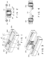
- Figs. 1 to 4 are perspective views and cross sectional views showing embodiments of a linear motor used with an optical card recording/reproducing apparatus according to the present invention.
- the recording/reproducing apparatus is constructed such that an optical card can be automatically mounted on and dismounted from a shuttle 20.
- This shuttle 20 is slidably held by two slide shafts 21 and 22 which are fixedly mounted in parallel with each other.
- An optical card is pulled in within the apparatus by a card pull-in mechanism (not shown) at a card inlet side, and placed on the shuttle 20.
- a moving coil 23 is provided movably inserted in juxtaposed linear yokes 25a and 25b.
- the moving coil 23 is wound without using a bobbin by bonding coil windings together. It is apparent that a bobbin may be made to make the moving coil 23.
- yokes 25a' and 25b' generally of a rectangular shape having an open side and opposite end portions being bent, are coupled to the linear yokes 25a and 25b, respectively, with linear gaps being interposed therebetween.
- the central linear areas of the other yokes 25a' and 25b' extend in parallel with the linear yokes 25a and 25b.
- Permanent magnets 26 and 27 are mounted inside of the one-side opened yokes 25a' and 25b' to generate magnetic fluxes traversing the moving coil 23 and generate magnetic fields propagating within the linear gaps in the same direction. In this manner, a linear motor is completed.
- the shuttle 20 When current flows through the moving coil 23, the shuttle 20 reciprocally moves along the slide shafts 21 and 22, the direction of motion being determined by the polarity of the current.
- Each of the permanent magnets 26 and 27 is constructed of a combination of magnets having different magnetic forces.
- the permanent magnet 26 is constructed of magnets 261 and 263 (such as samarium cobalt magnet) at opposite ends and a magnet 262 (a cheap magnet such as a ferrite magnet) at the center.
- the permanent magnet 27 is constructed of magnets 271 and 273 (such as samarium cobalt magnet) at opposite ends and a magnet 272 (a cheap magnet such as a ferrite magnet) at the center.
- the magnets at the opposite ends have a larger energy product than that of the center magnet.
- a light shielding plate (not shown) is mounted below the shuttle 20 for detecting the position of the shuttle 20 by shielding or exposing light.
- a scale (not shown) printed with a clock pattern, the scale being disposed along the direction of movement of the shuttle 20 and detected with a linear encoder sensor to generate an encoder pulse.
- the shuttle 20 is accelerated, decelerated, or stopped at the opposite end portions of the linear gaps, during the reciprocal motion of the shuttle 20 by the linear motor.
- a strong magnetic force is required at the acceleration/deceleration speed area, whereas not so strong magnetic force is required at a constant speed area intermediate between the opposite end portions. For example, if an acceleration speed is raised using a single magnet constituting a magnetic circuit, the magnetic force becomes too strong at the constant speed area.
- an outer dimension of the linear motor becomes correspondingly large and the cost becomes high.
- the magnets 261 and 263 of the permanent magnet 26 are constructed of magnets having a stronger magnetic force such as samarium cobalt magnets than that of the ferrite magnet 262 at the center at the constant speed area. Accordingly, a stronger thrust force (anti-thrust force) can be obtained for acceleration (deceleration) at the opposite end portions, while making the outer dimension of the yokes smaller than conventional. With the above arrangement, it is therefore possible to efficiently obtain a necessary thrust force.
- the ferrite magnet 262 at the center have the same thickness as that of the permanent magnets 261 and 263 at the opposite ends.
- the thickness of the magnet 262 may be made smaller than that of the opposite end magnets 261 and 263 so that the magnetic flux density at the gap of the central magnet 262 can be adjusted.
- Figs. 3 and 4 show another embodiment of the linear motor used with a recording/reproducing apparatus.
- like elements to those shown in Fig. 1 are represented by using identical reference numerals.
- moving coils 281 and 282 are used to obtain a thrust force, the moving coil 281 being provided for the combination of a linear yoke 25a, another yoke 25a', and a permanent magnet 26, and the moving coil 282 being provided for the combination of a linear yoke 25b, another yoke 25b', and a permanent magnet 27.
- the moving coils 281 and 282 are disposed at opposite sides of a shuttle 20 and are movable along the linear yokes 25a and 25b inserted into the coils.
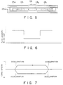
- Fig. 5 is a schematic diagram illustrating the concept of a linear motor.
- a yoke assembly is composed of a yoke 25a' and a linear yoke 25a extending in parallel with a gap interposed therebetween.
- a permanent magnet 26 is mounted at the side of the yoke 25a' for the generation of magnetic fluxes traversing a coil 281.
- the permanent magnet 26 is constructed of magnets 261 and 263 at opposite ends having a large energy product such as a samarium cobalt magnet, and a magnet 262 at the center having a small energy product such as a ferrite magnet. These magnets are bonded together with adhesive agent to form the integral permanent magnet 26.
- Fig. 6 shows a magnetic flux density at the gap between the permanent magnet and the linear yoke.
- the magnetic flux density at the opposite end portions is for example about 4000 Gausses, and that at the constant speed area is equal to or one half 4000 Gausses.
- Fig. 7 is a graph showing a card speed relative to a card position represented by the abscissa. As seen from the acceleration/deceleration characteristics of Fig. 7, rapid acceleration and deceleration can be achieved in a short time period.
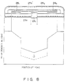
- Fig. 8 shows the magnetic circuit arrangement and its magnetic flux distribution according to another embodiment of this invention.
- a yoke assembly is composed of a yoke 25a' and a linear yoke 25a extending in parallel with a gap interposed therebetween.
- a permanent magnet 26 is mounted at the side of the yoke 25a' for the generation of magnetic fluxes traversing a coil 281.
- the permanent magnet 26 is constructed of magnets 261 and 263 at opposite ends having a large energy product such as a samarium cobalt magnet, and a magnet 262 at the center having a considerably small energy product such as a ferrite magnet. These magnets are bonded together with adhesive agent to form the integral permanent magnet 26. With this arrangement, the operating point of the magnetic circuit changes.
- Fig. 9 shows a change of the operating point of the magnetic circuit shown in Fig. 8.
- An operating point (P) at the magnetic flux density Bd and coercive force Hd changes to an operating point (P') at the magnetic flux density Bd'.
- Fig. 10 shows the waveform of a current flowing through the coil of the embodiment shown in Fig. 8.
- the acceleration pulse and deceleration pulse having a maximum value Is do not change at the acceleration/deceleration area, but the current at the constant speed area increases from Ib indicated by a broken line to Ic indicated by a solid line.
- Figs. 11 and 12 are a plan view and a cross sectional side view showing an example of a card transport apparatus using the embodiment of the linear motor shown in Fig. 8.
- Linear motors of the embodiment shown in Fig. 8 are mounted at opposite sides of a card transport stage 20 to move the stage 20 along guide shafts 22.
- Figs. 13 to 15 are a plan view, a side view, and a bottom view showing another example of a card transport apparatus using the embodiment of the linear motor shown in Fig. 8.
- a linear motor of the embodiment shown in Fig. 8 is mounted on the bottom of a card transport stage 20 which moves in the longitudinal direction of the yoke 25a, i.e., upward and downward as viewed in Figs. 13 and 14.
- Figs. 16 to 18 are a front view, a cross sectional side view, and a bottom view showing another example of a card transport apparatus using the embodiment of the linear motor shown in Fig. 8.
- a magnetic circuit is mounted on a plate having a small magnetic reluctance so that it can be made compact.
- Figs. 19 and 20 show a magnetic circuit composed of linear magnets 1261 and 1263 having a magnetic characteristic different from a magnet 1262.
- the magnets 1261, 1262, and 1263 have the same thickness so that the magnetic circuit can be formed compact or thin.
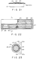
- Fig. 21 is a schematic diagram showing the card transport section of an optical recording/reproducing apparatus according to an embodiment of this invention.
- a shuttle 120 slides along slide shafts by the operation of a magnetic circuit 121 constituting a linear motor.
- Fig. 22 shows the structure of the linear motor of Fig. 21, and Fig. 23 is a cross sectional view taken along line A-A of Fig. 22.
- the optical card recording/reproducing apparatus of this embodiment is constructed such that an optical card can be automatically mounted on and dismounted from the shuttle 120.
- This shuttle 120 is slidably held by a pair of slide shafts 122a and 122b which are mounted at opposite sides of the linear motor in parallel with each other.
- Guide units 123 are provided under the shuttle 120 for coupling the shuttle 120 to the linear motor.
- An optical card is pulled in within the apparatus by a card pull-in mechanism (not shown) at a card inlet side, and placed on the shuttle 120.
- a card pull-in mechanism (not shown) at a card inlet side, and placed on the shuttle 120.
- a moving coil 124 which is inserted into inner yokes 125 and 125' and movable along the longitudinal direction of the yokes.
- the moving coil 124 is wound without using a bobbin by bonding coil windings together. It is apparent that a bobbin may be made to make the moving coil 124.
- the N poles of permanent magnets 126 and 126' are bonded to the opposite ends of the inner yokes 125 and 125', the permanent magnets generating magnetic fluxes traversing the moving coil 124.
- the S poles of the permanent magnets 126 and 126' are bonded to outer yokes 127 and 127'. In this manner, an inner-magnet type linear motor is completed.
- the inner yokes 125 and 125', outer yokes 127 and 127', and permanent magnets 126 and 126' are formed in a circular tube shape.
- the shape is not limited to this, but a rectangular tube shape may also be used.
- the magnetic circuit (linear motor) 121 is mounted at the center of a shuttle driver unit to reciprocally move the shuttle 120.
- the shuttle 120 reciprocally moves along the slide shafts 122a and 122b, the direction of motion being determined by the polarity of the current.
- a transport shaft 128 for fixing the moving coil of the linear motor to the bottom of the shuttle 120, the shaft 128 being allowed to move along a recess 129 within the motion span of the shuttle 120.
- the permanent magnets 126 and 126' are constructed of rare earth metal magnets such as samarium cobalt magnets having a stronger magnetic force than a ferrite magnet, so that the magnetic field can propagate to the central area of the inner yokes.
- a light shielding plate (not shown) is mounted below the shuttle 120 for detecting the position of the shuttle 120 by shielding or exposing light.
- a scale (not shown) printed with a clock pattern, the scale being disposed along the direction of movement of the shuttle 120 and detected with a linear encoder sensor to generate an encoder pulse.
- the shuttle 120 is accelerated, decelerated, or stopped at the opposite end portions of the linear gaps, during the reciprocal motion of the shuttle 120 by the linear motor.
- a strong magnetic force is required at the acceleration/deceleration speed area, whereas not so strong magnetic force is required at a constant speed area intermediate between the opposite end portions. For example, if an acceleration speed is raised using a single magnet constituting a magnetic circuit, the magnetic force becomes too strong at the constant speed area.
- an outer dimension of the linear motor becomes correspondingly large and the cost becomes high.
- the magnets such as samarium cobalt magnets having a stronger magnetic force than a ferrite magnet are disposed within the linear motor at opposite end portions thereof. Accordingly, a stronger thrust force (anti-thrust force) can be obtained for acceleration (deceleration) at the opposite end portions, and a weaker magnetic field is applied to the central constant speed area, while making the outer dimension of the yokes smaller than conventional. With the above arrangement, it is therefore possible to make a linear motor of low cost and efficiently obtain a necessary thrust force.
- Fig. 24(a) shows the distribution of the magnetic gap length between the outer and inner yokes.
- the magnetic gap length is short at opposite end portions of the linear motor in the longitudinal direction, and long at the intermediate area.
- Fig. 24(b) shows a necessary driving force relative to the coil position. A large driving force becomes necessary at opposite end portions of the linear motor in the longitudinal direction.
- Fig. 24(c) shows a necessary driving current for the driving force shown in Fig. 24(b) relative to the coil position.
- a positive acceleration pulse is applied at the right end and a negative deceleration pulse at the left end
- a negative acceleration pulse is applied at the left end and a positive deceleration pulse at the right end.
- Fig. 24(d) shows a card speed relative to the coil position.
- the acceleration/deceleration area is at opposite end portions of the linear motor, and the constant speed area is at the intermediate section.
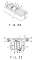
- Figs. 25 to 27 show another embodiment of a linear motor.
- the operation and effect of this embodiment are the same as those of the above-described inner-magnet type linear motor, so the outline thereof is omitted and only the difference therebetween will be described.
- the difference is that permanent magnets 130 and 130' are mounted on outer yokes at opposite end portions to form an outer-magnet type linear motor.
- Figs. 28 to 31 show an embodiment of a card transport unit according to the present invention.
- Fig. 28 is a side view of the unit
- Fig. 29 is a plan view of the unit
- Fig. 30 is a side view partially broken.
- an optical card information recording/reproducing apparatus is constructed such that an optical card can be automatically mounted on and dismounted from a card transport stage 220 (hereinafter called a shuttle).
- This shuttle 220 has slide bearings 222a and 222b formed at the bottom of the shuttle 220, and is slidably held by two guide shafts 221a and 221b which are fixedly mounted in parallel with each other at substantially the central area of the shuttle transport unit C.
- the guide shafts 221a and 221b are inserted into the slide bearings 222a and 222b so that the shuttle 220 is guided along the guide shafts 221a and 221b.
- the guide shafts 221a and 221b are pushed and fixed in position by plate springs at opposite ends of the shafts.
- An optical card is pulled in within the apparatus by a card pull-in mechanism (not shown) at a card inlet side, and placed on the shuttle 220.
- a card pull-in mechanism (not shown) at a card inlet side, and placed on the shuttle 220.
- moving coils 223 wound about bobbins 224 are fixedly mounted at opposite sides of the shuttle 220.
- Inner driving yokes 225b and 225b' are inserted within the bobbins 224.
- the moving coils 223 are wound on the bobbins 224.
- the moving coil may be made without using a bobbin by bonding coil windings together.
- yokes 225a and 225a' generally of a rectangular shape having an open side and opposite end portions being bent, are coupled to the inner yokes 225b and 225b'.
- Permanent magnets are mounted on the inside of the other yokes, the magnets having a magnetic force sufficiently large for generating magnetic fluxes traversing the moving coils 223.
- the linear motor is completed.
- Two linear motors are provided at opposite sides of the shuttle transport unit to thereby reciprocally move the shuttle 220. When current flows through the moving coils 223, the shuttle 220 reciprocally moves along the guide shafts 221a and 221b, the direction of motion being determined by the polarity of the current.
- Each of the permanent magnets 226 is constructed of a combination of two types of magnets having different magnetic forces. Namely, the permanent magnet 226 is constructed of magnets 226a and 226b having a large energy product of magnetic force such as samarium cobalt magnet at opposite ends and a magnet 226c having a smaller energy product of magnetic force than that of the magnets 226a and 226b such as a ferrite magnet at the center.
- a light shielding plate 227 is mounted below the shuttle 220 for detecting the position of the shuttle 220 by interrupting or not interrupting light from an interrupter 228.
- a scale 229 printed with a clock pattern, the scale being disposed below the shuttle 220 along the direction of movement of the shuttle 220 and detected with a linear encoder sensor 230 to generate an encoder pulse.
- the card transport unit is constructed such that the plane of the driving force of the linear motor operating as driving means for the card transport stage 220 (shuttle) is made flush with the centers of the guide shafts 221a and 221b. The plane and centers are aligned in line as a reference shown in Fig. 31.
- the shuttle 220 using the linear motor is accelerated, decelerated, or stopped at the opposite end portions of the linear gaps, during the reciprocal motion of the shuttle 220 by the linear motor.
- the plane of driving force of the linear motor is not flush with the centers of the guide shafts at the acceleration/deceleration speed area.
- abnormal vibrations and noises are likely to occur.
- frictional resistance between the guide shafts and slide bearings becomes large, adversely effecting information recording/reproducing.
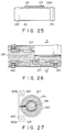
- Figs. 32 and 33 are a plan view and a side view showing another embodiment of an optical head transport unit.
- the optical head transport unit reciprocally moves the optical head transport stage from which a laser beam is radiated, and uses linear motors as a driving means.
- the optical head transport stage 231 has an optical head for radiating a laser beam.
- Two parallel guide shafts 232a and 23wb are mounted at opposite sides of the optical head transport stage 231.
- the two guide shafts 232a and 232b are received by two slide bearings 233a and 233b mounted at opposite sides of the optical head transport stage 231, so that the transport stage 231 can be guided by the guide shafts 232a and 232b.
- Moving coil type linear motors are provided at opposite sides of the optical head transport stage 231 to thereby move the optical head stage 231 up and down as viewed in the plan view of Fig. 32.
- yokes 235a and 235b On one sides of the guide shafts, yokes 235a and 235b generally of a rectangular shape having an open side are mounted on support plates 234a and 234b, and joined to inner yokes 236a and 236b. Permanent magnets 237a and 237b magnetized in its thickness direction are mounted inside of the outer yokes 235a and 235b. The inner yokes 236a and 236b are inserted into moving coils 238a and 238b connected to the opposite sides of the optical head transport stage 231.
- an encoder scale 239 for detecting the position and speed of the transport stage.
- the encoder scale 239 is read by an encoder sensor 240 fixedly mounted on the support plate 234a.
- the optical head transport stage 231 moves forward and backward.
- the centers of the guide shafts 232a and 232b are made flush with the plane of driving force by the moving coils 238a and 238b constituting the linear motor driving unit.
Landscapes
- Engineering & Computer Science (AREA)
- Physics & Mathematics (AREA)
- Chemical & Material Sciences (AREA)
- Combustion & Propulsion (AREA)
- Electromagnetism (AREA)
- Power Engineering (AREA)
- Reciprocating, Oscillating Or Vibrating Motors (AREA)
- Non-Mechanical Conveyors (AREA)
- Moving Of Heads (AREA)
Applications Claiming Priority (7)
| Application Number | Priority Date | Filing Date | Title |
|---|---|---|---|
| JP9350590 | 1990-04-09 | ||
| JP9350690A JPH03293956A (ja) | 1990-04-09 | 1990-04-09 | リニアモータ |
| JP93506/90 | 1990-04-09 | ||
| JP93505/90 | 1990-04-09 | ||
| JP9721690A JPH03295069A (ja) | 1990-04-12 | 1990-04-12 | 情報記録再生装置 |
| JP97216/90 | 1990-04-12 | ||
| EP91105570A EP0451773B1 (de) | 1990-04-09 | 1991-04-09 | Linearmotor |
Related Parent Applications (1)
| Application Number | Title | Priority Date | Filing Date |
|---|---|---|---|
| EP91105570.5 Division | 1991-04-09 |
Publications (2)
| Publication Number | Publication Date |
|---|---|
| EP0608008A2 true EP0608008A2 (de) | 1994-07-27 |
| EP0608008A3 EP0608008A3 (de) | 1994-10-05 |
Family
ID=27307300
Family Applications (2)
| Application Number | Title | Priority Date | Filing Date |
|---|---|---|---|
| EP91105570A Expired - Lifetime EP0451773B1 (de) | 1990-04-09 | 1991-04-09 | Linearmotor |
| EP9494105357A Ceased EP0608008A3 (de) | 1990-04-09 | 1991-04-09 | Linearmotor. |
Family Applications Before (1)
| Application Number | Title | Priority Date | Filing Date |
|---|---|---|---|
| EP91105570A Expired - Lifetime EP0451773B1 (de) | 1990-04-09 | 1991-04-09 | Linearmotor |
Country Status (4)
| Country | Link |
|---|---|
| US (1) | US5341053A (de) |
| EP (2) | EP0451773B1 (de) |
| DE (1) | DE69116918T2 (de) |
| ES (1) | ES2085367T3 (de) |
Families Citing this family (7)
| Publication number | Priority date | Publication date | Assignee | Title |
|---|---|---|---|---|
| JPH07201144A (ja) * | 1993-12-28 | 1995-08-04 | Nippon Conlux Co Ltd | 情報記録再生装置 |
| US5606206A (en) * | 1995-04-10 | 1997-02-25 | Eastman Kodak Company | Device for detecting the position of an optical or magnetic head used on linear motors |
| JP3815750B2 (ja) * | 1995-10-09 | 2006-08-30 | キヤノン株式会社 | ステージ装置、ならびに前記ステージ装置を用いた露光装置およびデバイス製造方法 |
| US6870285B2 (en) | 2001-02-27 | 2005-03-22 | Bei Technologies, Inc. | Long stroke linear voice coil actuator with the proportional solenoid type characteristic |
| BRPI0617853A2 (pt) * | 2005-10-25 | 2011-08-09 | Ematech Inc | atuador usando força eletromagnética e disjuntor |
| EP1816725A1 (de) * | 2006-02-03 | 2007-08-08 | University of Teheran | Permanentmagnetanordnung für elektrische Maschines und Aktuatoren, Entwurfsverfahren und elektrische Maschinen und Aktuatoren. |
| DE102006014616A1 (de) * | 2006-03-29 | 2007-10-11 | Siemens Ag | Linearmotor mit verschieden gestalteten Sekundärteilabschnitten |
Family Cites Families (25)
| Publication number | Priority date | Publication date | Assignee | Title |
|---|---|---|---|---|
| US3149254A (en) * | 1961-08-07 | 1964-09-15 | Thomas A Carter | Linear motor or generator |
| DE2527461C2 (de) * | 1975-06-20 | 1987-01-02 | Robert Bosch Gmbh, 7000 Stuttgart | Verfahren zur Herstellung von anisotropen Segmentmagneten für elektrische Maschinen |
| DE2845264A1 (de) * | 1978-10-18 | 1980-05-08 | Bosch Gmbh Robert | Elektrische maschine, insbesondere kleinmotor |
| US4692999A (en) * | 1979-12-26 | 1987-09-15 | Unisys Corp. | Method of making a multi-coil/multi-magnet actuator |
| JPS56145770A (en) * | 1980-04-09 | 1981-11-12 | Ricoh Co Ltd | Linear motor |
| JPS5759464A (en) * | 1980-09-29 | 1982-04-09 | Hitachi Ltd | Field pole for dc electric machine |
| JPS57110069A (en) * | 1980-12-26 | 1982-07-08 | Fujitsu Ltd | Voice coil type linear motor |
| US4414594A (en) * | 1982-02-26 | 1983-11-08 | Atasi Corporation | Linear actuator for a memory storage apparatus |
| IT1150787B (it) * | 1982-04-06 | 1986-12-17 | Ages Spa | Lettore ottico per codici a barre |
| US4438362A (en) * | 1982-08-19 | 1984-03-20 | Rotron, Incorporated | Self-starting, direct current motor with permanent magnets of varied magnetic strength |
| JPS59223887A (ja) * | 1983-06-01 | 1984-12-15 | Seiko Instr & Electronics Ltd | カ−ド式光情報記録媒体およびその情報録再方式 |
| JPS6069868A (ja) * | 1983-09-27 | 1985-04-20 | Toshiba Corp | 磁気ディスク装置のヘッドアクセス機構 |
| JPH0732583B2 (ja) * | 1985-10-28 | 1995-04-10 | ソニー株式会社 | リニアモ−タ |
| JPS62114459A (ja) * | 1985-11-14 | 1987-05-26 | Hitachi Metals Ltd | リニアモ−タ |
| JPS62173968A (ja) * | 1986-01-28 | 1987-07-30 | Sumitomo Special Metals Co Ltd | ボイスコイルモ−タ |
| JPS62229531A (ja) * | 1986-03-31 | 1987-10-08 | Canon Inc | 光学式情報記録再生装置 |
| JPS6348149A (ja) * | 1986-08-12 | 1988-02-29 | Alps Electric Co Ltd | 送り装置 |
| US4888506A (en) * | 1987-07-09 | 1989-12-19 | Hitachi Metals, Ltd. | Voice coil-type linear motor |
| US4853808A (en) * | 1987-10-30 | 1989-08-01 | Cardiff Technology Inc. | Linear actuator for disc drive |
| JP2778032B2 (ja) * | 1988-01-27 | 1998-07-23 | ソニー株式会社 | 光学ピックアップ装置 |
| US4945330A (en) * | 1988-03-28 | 1990-07-31 | Mitsubuishi Kasei | Actuator |
| JPH0752555B2 (ja) * | 1988-07-06 | 1995-06-05 | キヤノン株式会社 | 光学式情報記録再生装置 |
| JPH0223058A (ja) * | 1988-07-06 | 1990-01-25 | Nhk Spring Co Ltd | カードリーダライタ用リニアモータ構造 |
| JPH0265647A (ja) * | 1988-08-29 | 1990-03-06 | Hitachi Ltd | 磁気ディスク装置のボイスコイルモータ |
| JPH0442765A (ja) * | 1990-06-08 | 1992-02-13 | Sony Corp | リニヤモータ |
-
1991
- 1991-04-09 US US07/682,691 patent/US5341053A/en not_active Expired - Fee Related
- 1991-04-09 ES ES91105570T patent/ES2085367T3/es not_active Expired - Lifetime
- 1991-04-09 EP EP91105570A patent/EP0451773B1/de not_active Expired - Lifetime
- 1991-04-09 DE DE69116918T patent/DE69116918T2/de not_active Expired - Fee Related
- 1991-04-09 EP EP9494105357A patent/EP0608008A3/de not_active Ceased
Also Published As
| Publication number | Publication date |
|---|---|
| US5341053A (en) | 1994-08-23 |
| EP0451773B1 (de) | 1996-02-07 |
| DE69116918D1 (de) | 1996-03-21 |
| DE69116918T2 (de) | 1996-07-25 |
| ES2085367T3 (es) | 1996-06-01 |
| EP0451773A2 (de) | 1991-10-16 |
| EP0451773A3 (en) | 1992-05-20 |
| EP0608008A3 (de) | 1994-10-05 |
Similar Documents
| Publication | Publication Date | Title |
|---|---|---|
| EP0326374B1 (de) | Linearmotor mit beweglicher Spule | |
| US4386823A (en) | Objective lens driving device | |
| US5165088A (en) | Optical pickup with bilateral and vertical symmetry | |
| US5341053A (en) | Linear motor with permanent magnets | |
| US4678951A (en) | Linear motor | |
| US4553227A (en) | Optical pickup | |
| KR100708093B1 (ko) | 광픽업 조립체 | |
| EP0486275B1 (de) | Treibervorrichtung einer Objektivlinse | |
| US4823219A (en) | Carriage recording head sandwiched by electromagnetic coil sections | |
| JPS5849099B2 (ja) | 可動コイル型リニアモ−タ | |
| US7199949B2 (en) | Optical pickup device and optical disk device | |
| EP0353074A2 (de) | Linearantrieb | |
| JPH03293956A (ja) | リニアモータ | |
| EP0224377A2 (de) | Geschwindigkeitsmessaufnehmer | |
| JPH04222451A (ja) | リニアモータ | |
| US6785202B1 (en) | Magnetic restoring device of an actuator | |
| JPH0237129Y2 (de) | ||
| JP3272073B2 (ja) | 電磁駆動装置 | |
| JPS6139241A (ja) | 対物レンズ駆動装置 | |
| KR100354063B1 (ko) | 픽업액츄에이터 | |
| JPH05334692A (ja) | 光学ヘッド駆動装置及び光ディスク装置 | |
| JPH06119725A (ja) | ボイスコイル型リニアモータ | |
| JP3488253B2 (ja) | 速度検出装置 | |
| JPS62134832A (ja) | 光学ヘツド用アクチユエ−タ | |
| JPH05298838A (ja) | 光学ヘッド駆動装置 |
Legal Events
| Date | Code | Title | Description |
|---|---|---|---|
| PUAI | Public reference made under article 153(3) epc to a published international application that has entered the european phase |
Free format text: ORIGINAL CODE: 0009012 |
|
| AC | Divisional application: reference to earlier application |
Ref document number: 451773 Country of ref document: EP |
|
| AK | Designated contracting states |
Kind code of ref document: A2 Designated state(s): CH DE ES FR GB IT LI SE |
|
| PUAL | Search report despatched |
Free format text: ORIGINAL CODE: 0009013 |
|
| 17P | Request for examination filed |
Effective date: 19940719 |
|
| AK | Designated contracting states |
Kind code of ref document: A3 Designated state(s): CH DE ES FR GB IT LI SE |
|
| 17Q | First examination report despatched |
Effective date: 19950921 |
|
| STAA | Information on the status of an ep patent application or granted ep patent |
Free format text: STATUS: THE APPLICATION HAS BEEN REFUSED |
|
| 18R | Application refused |
Effective date: 19960516 |