EP0608499A1 - Système de réservoir de carburant liquide, notamment pour moteur à combustion pour véhicules à moteur - Google Patents
Système de réservoir de carburant liquide, notamment pour moteur à combustion pour véhicules à moteur Download PDFInfo
- Publication number
- EP0608499A1 EP0608499A1 EP93118064A EP93118064A EP0608499A1 EP 0608499 A1 EP0608499 A1 EP 0608499A1 EP 93118064 A EP93118064 A EP 93118064A EP 93118064 A EP93118064 A EP 93118064A EP 0608499 A1 EP0608499 A1 EP 0608499A1
- Authority
- EP
- European Patent Office
- Prior art keywords
- tank
- fuel
- reserve tank
- line
- flow
- Prior art date
- Legal status (The legal status is an assumption and is not a legal conclusion. Google has not performed a legal analysis and makes no representation as to the accuracy of the status listed.)
- Granted
Links
Images






Classifications
-
- B—PERFORMING OPERATIONS; TRANSPORTING
- B60—VEHICLES IN GENERAL
- B60K—ARRANGEMENT OR MOUNTING OF PROPULSION UNITS OR OF TRANSMISSIONS IN VEHICLES; ARRANGEMENT OR MOUNTING OF PLURAL DIVERSE PRIME-MOVERS IN VEHICLES; AUXILIARY DRIVES FOR VEHICLES; INSTRUMENTATION OR DASHBOARDS FOR VEHICLES; ARRANGEMENTS IN CONNECTION WITH COOLING, AIR INTAKE, GAS EXHAUST OR FUEL SUPPLY OF PROPULSION UNITS IN VEHICLES
- B60K15/00—Arrangement in connection with fuel supply of combustion engines or other fuel consuming energy converters, e.g. fuel cells; Mounting or construction of fuel tanks
- B60K15/03—Fuel tanks
- B60K15/077—Fuel tanks with means modifying or controlling distribution or motion of fuel, e.g. to prevent noise, surge, splash or fuel starvation
Definitions
- the invention relates to a tank system for liquid fuel, in particular for internal combustion engines in motor vehicles, with a main and a reserve tank, a feed line leading from the main tank to the reserve tank, a feed line with feed pump leading from the reserve tank to the consumer or internal combustion engine and one from the consumer or Internal combustion engine to the return line leading to the tank system.
- the reserve tank which is additionally connected to the main tank via a ventilation opening or a ventilation channel, is refilled by means of an injector pump which conveys fuel from the main tank via the supply line into the reserve tank.
- the injector nozzle of this pump is fed via a pressure line, which branches off the flow line on the pressure side of the flow pump.
- a pressure-controlled shut-off valve is arranged in the feed line, which opens only when a pressure threshold value is exceeded in the feed line on the feed pump side.
- a valve is also arranged in the pressure line feeding the injector of the injector pump, which valve is only exceeded when it is exceeded opens a pressure threshold and then allows fuel to flow to the injector nozzle.
- This tank system has a comparatively complicated construction.
- malfunctions can occur at least when it can be expected that the fuel, e.g. Diesel oil, can become viscous or even waxy at lower temperatures.
- the valves can clog comparatively easily.
- the flow line is normally connected to the main tank.
- the reserve tank is inevitably filled via the return line when the main tank is filled.
- the return fuel is transferred from the reserve tank to the main tank via an overflow line.
- the reserve tank can be connected to the supply line by switching valves.
- too many valves are undesirably provided, which can clog under unfavorable operating conditions.
- the object of the invention is now to improve the function of a tank system of the type specified at the outset with a constructional simplification.
- the reserve tank can be refilled from the main tank using the underpressure generated on the suction side by the feed pump and is provided with a forced ventilation.
- the fuel is thus led from the main tank via the reserve tank to the consumer or internal combustion engine, only the suction vacuum of the feed pump being used to maintain the fuel flow.
- the reserve tank Due to the forced ventilation, the reserve tank is inevitably filled when the main tank is filled and even when the main tank is slightly filled. This filling state is maintained as long as a sufficient amount of fuel can flow in via the supply line.
- the main tank When the main tank is increasingly emptied, it must then be expected that air will also be sucked in via the feed line. However, this is subsequently discharged again via the forced ventilation of the reserve tank if corresponding residual quantities of fuel from the main tank still reach the feed line.
- the inlet opening of the feed line is arranged in an open collecting zone for fuel in the main tank and the return line opens into this collecting zone. This inevitably ensures that the fuel flowing through the feed line is largely free of air. It is also advantageous that the returning fuel, which was usually heated in a heater upstream of the internal combustion engine, is also able to heat the entrance area of the feed line and accordingly keeps the fuel at the inlet of the feed line well liquid even at cold temperatures.
- the return flow of the fuel can be used for the operation of a fluid dynamic pumping device for venting the reserve tank.
- a fuel filter is usually arranged between the consumer or motor and feed pump, which must be provided with a vent anyway, and from the outlet side of the fuel usually by means of another pump , in the case of an internal combustion engine by means of the injection pump, to the consumer or engine and to the return line.
- the reserve tank can be vented using the suction vacuum of the feed pump, for example, by arranging an injector pump operated by the suction vacuum in the reserve tank and connecting its suction side to the upper area of the reserve tank, with the inlet line downstream of the injector pump having an outlet opening has, which is adjacent to an inlet opening of the flow line or combined therewith and is arranged under a shield which at least substantially prevents air bubbles from rising upwards and facilitates penetration of the air bubbles into the inlet opening.
- an additional air intake pipe can also be provided, the inlet of which is arranged in the upper region of the reserve tank and the outlet of which opens into the feed line, the outlet being more or less far away from the inlet of the feed line in the flow direction of the fuel.
- a section of the supply line forms a downpipe through which the fuel is supplied and flows from top to bottom with a first opening communicating with the upper region of the reserve tank and a second opening (outlet) communicating with the lower region of the reserve tank. which is adjacent to an inlet opening of the flow line or combined therewith and is arranged under a shield of the type specified above.
- an injection pump 1 of an internal combustion engine 2 which is only shown schematically, is connected on the input side to a fuel filter 3 and on the output side to a return line 4, via which excess fuel not required by the internal combustion engine 2 is returned to a main tank 5, which is used as a fuel reservoir for the internal combustion engine 2 is provided.
- the main tank 5 has two tank parts 5 ′ and 5 ′′ connected to one another via an overflow.
- An injector pump 6 is arranged on the return line 4, the injector nozzle of which the fuel flowing back through the return line 4 passes through and the suction connection 7 of which communicates with a lower region of the tank part 5 ', so that fuel can be drawn from the tank part 5 'with the injector pump 6 and fed to a defoaming device 8 together with the fuel flowing back from the injection pump 1, from which the fuel runs out into a fuel collecting zone 9 in the tank part 5''.
- the collecting zone 9 has an opening leading to the lower region of the tank part 5 ′′, which is arranged in the immediate vicinity of the inlet opening of a feed line 10, via which a reserve tank 11 on the inlet side with the tank part 5 ′′. connected is.
- an injector pump 12 is arranged on the feed line 10, the injector nozzle of which the fuel flowing through the feed line 10 passes through and the suction connection 13 of which is connected to the upper region of the reserve tank 11, in such a way that air which may be located there is sucked in and is carried along with the fuel flowing through the injector pump 12 to the outlet 14 of the feed line 10 connected to the lower region of the reserve tank 11.
- the outlet 14 of the feed line 10 is arranged directly adjacent to the inlet 15 of a feed line 16, via which the reserve tank 11 is connected to the suction side of a feed or fuel pump 17.
- Outlet 14 and inlet 15 are arranged under a shield 18 covering both that on the one hand fuel can flow into the reserve tank 11 from the outlet 14 and on the other hand it is prevented that larger amounts of fuel from the Exit outlet 14 with carried air in the upper area of the reserve tank 11. Rather, this air is predominantly taken up by the inlet 15 of the feed line 16 when the feed pump 17 is operating.
- the pressure side of the feed pump 17 is connected to the input of the fuel filter 3, which is provided with a ventilation line 19, via which the air entrained in the fuel is transferred into the return line 4.
- the suction vacuum of the feed pump 17 is used on the one hand to draw fuel from the collecting zone 9 or the tank part 5 ′′ into the reserve tank 11 and the feed line 16 via the feed line 10.
- the fuel flow drawn in operates the injector pump 12 to vent the reserve tank 11, so that the feed pump 17 discharges a fuel-air mixture via the feed line 16 from the reserve tank 11 and the reserve tank 11 is filled with fuel within a short time, provided that on the fuel collection zone 9 is still fuel.
- the reserve tank 11 will temporarily absorb air and fuel at times when the feed pump 17 is operating, depending on the presence of fuel at the inlet of the feed line 10, in the latter case in each case ventilation of the reserve tank 11 is also effected when the tank is refilled.
- the reserve tank 11 acts in the manner of a buffer store for fuel and ensures a constant fuel flow to the feed pump 17.
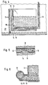
- FIG. 2 the reserve tank 11 of Fig. 1 is shown again enlarged. It can be seen that the outlet 14 of the feed line 10 and the inlet 15 of the feed line 16 are arranged within the reserve tank 11 and are designed as a common slot-like opening on the underside of a tube, connected to one another via the feed and feed line 10 and 16 within the reserve tank 11 are.
- the part of the feed line 10 adjoining the injector pump 12 and the feed line 16 are arranged essentially outside the reserve tank 11, but are connected to it via an extension 20.
- This connection area is shown in cross section in FIG. 6.
- the feed line 10 and the flow line 16 essentially form one horizontal tube, which communicates downward or obliquely downward with the extension 20 via a large opening which on the one hand forms the outlet 14 of the feed line 10 and on the other hand forms the inlet 15 of the feed line 16.
- the upper side of the aforementioned tube forms the shield 18, under which air bubbles carried by the fuel in the supply line 10 are held captive and guided into the inlet 15 of the supply line 16.
- FIG. 4 corresponds functionally to the embodiment according to FIG. 2, but with the difference that the part of the feed line 10 adjoining the injector pump 12 is arranged on a wall area of this tank within the reserve tank 11 and that at the opening 14 dynamic pressure occurring due to the angled flow guidance is used to accelerate the filling of the reserve tank 11.
- the injector pump 12 is shown enlarged in FIG. 7.
- the injector nozzle is formed by a section 10 'of the feed line 10 with a very narrow cross section. This section 10 'opens from obliquely sideways into a downward-leading part of the feed line 10, the suction connection 13 of the injector pump 12 being arranged directly next to the mouth of the section 10', which is connected to the section 10 'at an acute V-shape .
- the oblique arrangement of the section 10 'forming the injector nozzle ensures that the fuel jet emerging from the section 10' impinges obliquely against a wall section 10 '', so that the fuel jet is mixed with small-volume air bubbles due to the intensive vortex formation. This will the otherwise possibly existing danger avoided that an almost stationary large air bubble can form behind the section 10 ′′ in the direction of flow.
- the wall section 10 ′′ according to FIG. 8 can have a wave-like rough surface in order to tear the fuel jet even more and to achieve an intensive mixing of the fuel with small air bubbles.
- the feed line 10 in the flow direction behind the section 10 'forming the injector nozzle can be labyrinth-like and can be provided with interfering contours 21 in the further course in order to enable particularly intensive swirling of fuel and air to form very small air bubbles.
- the suction connection 13 which is not shown in more detail in FIG. 9, has two orifices 13 'and 13' 'next to the nozzle section 10'.
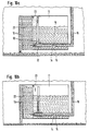
- the significantly lower throttle resistance of the air causes the pressure difference at the throttle bore 23 and thus also the negative pressure in the reserve tank 11 to collapse, so that fuel is drawn from the reserve tank 11 through the opening 15 into the feed line 16. If the degassing chamber 22 is only or largely filled with air, the flow pump 17 pumps the remaining fuel in the reserve tank 11 via the inlet 15 of the flow line 16.
- the degassing chamber 22 is completely filled with fuel according to FIG. 10 a, as is regularly the case when the fuel level in the main tank 5 is significantly above the inlet of the supply line 10, fuel may possibly also pass through the throttle opening 23 into the reserve tank 11 . Due to the throttle resistance of the throttle opening 23, however, the fuel flows out of the degassing chamber 22 essentially via the injector pump 12, so that it can effectively remove the air from the reserve tank.
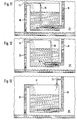
- the feed line 10 opens into the upper region of the reserve tank 11, and the feed line 16 has its inlet 15 in the lower region of the reserve tank 11.
- a ventilation line 36 is arranged, which projects with its lower end more or less far into the feed line, so that the fuel flowing into the feed line 16 via the Vent line 36 can entrain air from the upper region of the reserve tank 11.
- the ventilation line 36 opens into the flow line 16 from the side behind the inlet 15 of the flow line 16.
- the lower end of the vent line 36 is cut off obliquely such that the lower opening of the vent line 36 points essentially in the flow direction of the fuel in the feed line 16.
- the fuel flowing into the feed line 16 can entrain air from the upper region of the reserve tank.
- the effect is used for venting the reserve tank 11 that a dynamic negative pressure occurs in the flowing fuel at the lower open end of the vent line 36 due to fluid dynamic effects. This is because the part of the vent line 36 protruding into the supply line 16 forms a narrowing of the open cross section within the supply line 16, so that comparatively high flow velocities and correspondingly low dynamic pressures occur.
- the flow line 16 is connected to the upper region of the tank 11 via a throttled ventilation line 37.
- a throttled ventilation line 37 is dimensioned such that even if only air flows into the reserve tank 11 via the feed line 10 (for example because the main tank 5 is emptied), in the section of the feed line 16 between the inlet 15 and the vent line 37 a sufficient negative pressure can still be generated to pump fuel from the lower region of the reserve tank 11.
- the feed line 10 forms a downpipe in or on the reserve tank 1, which communicates with the uppermost region of the reserve tank 11 via a small opening 24 and at its lower end via the outlet 14 with the lowermost region of the reserve tank 11 is connected.
- the inlet 15 of the feed line 16 again connects, in such a way that air bubbles carried in the fuel are prevented by a shield 18 from rising into the upper region of the reserve tank 11 and are largely fed to the feed line 16.
- the fuel flow which passes through the supply line 10 can take up and carry air from the upper region of the reserve tank 11 in the area of the opening 24 due to the air access there. These air quantities are then covered by the fuel trailing through the feed line 10, so that air bubbles entrained in the fuel flow form in the downpipe part of the feed line 10.
- the passage of air from the upper region of the reserve tank 11 through the opening 24 into the fuel-carrying supply line 10 is caused by the pressure difference at the opening 24, which according to the laws of communicating vessels, the difference in the fuel level in the reserve tank 11 compared to the height of the fuel column in Down pipe part depends on the connection opening 24 - taking into account the reduced average density due to the air bubbles carried by the fuel.
- the reserve tank 11 can in turn be effectively vented.
- the venting effect is particularly effective if the opening 24 is arranged in such a way that the fuel flowing through the supply line 10 cannot easily flow into the opening 24.
- the downpipe part of the feed line 10 should on the one hand have a sufficiently large cross-section to avoid any risk of clogging even when the fuel is temporarily heavy.
- this area should also not have an unnecessarily large cross section in order to enable a sufficiently high flow velocity of the fuel for carrying the air bubbles.
- the embodiment according to FIG. 15 differs from the embodiment according to FIG. 14 essentially only in that the inlet 15 of the feed line 16 forms a cup which is open towards the bottom and largely covers the outlet 14 of the feed line 10, from which the fuel Air bubbles carried along in the feed line 10 can be captured particularly effectively and can thus be fed to the feed line 16.
- the flowing liquid is deflected by 180 o after it emerges from the opening 14 of the downpipe part, as a result of which the dynamic pressure that acts in the fuel of the reserve tank and thus the pressure difference at the connection opening 24 is further increased. This effect can compensate for the flow losses occurring in the downpipe part, in particular at high flow velocities.
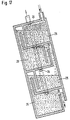
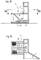
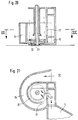
- the defoaming device 8 can, according to FIG. 1, essentially consist of several, in the example shown, three chambers 25 arranged one behind the other in the direction of flow, which are arranged next to one another and separated from one another by walls, in the lower regions of which there are openings 25 for connecting the chambers. In the upper region, the chambers 25 are connected to the main tank 5 via ventilation openings 26. The last chamber 25 in the direction of flow has a lateral opening from which the fuel runs out to the collecting zone 9.
- double walls can also be arranged between the chambers 25, the space between the double walls being connected to the front chamber 25 in the flow direction via lower openings and to the downstream chamber 25 via upper openings.
- the advantage of this embodiment is that the amounts of fuel absorbed by the defoaming device 8 are largely the same, even when the defoaming device 8 is at an angle.
- the chambers 25 can also be arranged one above the other, the outflow sides of the chambers 25 being arranged alternately on one and the other side.
- the fuel flows from the defoaming device 8 to the fuel collecting zone 9.
- the fuel falls through a window 27 into a funnel 28 which has a slot 29 on its underside through which the fuel flows directly in front of the inlet 30 of the feed line 10.
- the slot 29 is dimensioned so that the fuel from the funnel 28 is comparatively slow runs out, ie the flow rate flowing through the slot 29 corresponds approximately to the flow rate flowing through the return line 4, so that the funnel 28 can practically not run empty.
- the fuel falls through the window 27 into a collecting cup 32 which is connected to the feed line 10 at its bottom via a slot 33, which can also be replaced by several smaller openings. ie the slot 33 or the openings provided instead form the entrance of the feed line 10.
- fuel from the tank part 5 ′′ can flow into the latter via a channel 34 which spirally surrounds the collecting cup 32 and a lateral opening 35 in the peripheral wall of the collecting cup 32. Even when the collecting cup 32 is in an inclined position, due to the spiral shape of the channel 34, only comparatively little fuel can run out of the collecting cup 32 to the tank part 5 ′′. In practice, the entire fuel content of the collecting cup 32 is supplied to the feed line 10 via the slot 33 or the corresponding openings.
Landscapes
- Engineering & Computer Science (AREA)
- Life Sciences & Earth Sciences (AREA)
- Sustainable Development (AREA)
- Sustainable Energy (AREA)
- Chemical & Material Sciences (AREA)
- Combustion & Propulsion (AREA)
- Transportation (AREA)
- Mechanical Engineering (AREA)
- Cooling, Air Intake And Gas Exhaust, And Fuel Tank Arrangements In Propulsion Units (AREA)
Applications Claiming Priority (2)
| Application Number | Priority Date | Filing Date | Title |
|---|---|---|---|
| DE19934301761 DE4301761C2 (de) | 1993-01-23 | 1993-01-23 | Tanksystem für flüssigen Kraftstoff, insbesondere für Verbrennungsmotoren in Kraftfahrzeugen |
| DE4301761 | 1993-01-23 |
Publications (2)
| Publication Number | Publication Date |
|---|---|
| EP0608499A1 true EP0608499A1 (fr) | 1994-08-03 |
| EP0608499B1 EP0608499B1 (fr) | 1997-03-19 |
Family
ID=6478767
Family Applications (1)
| Application Number | Title | Priority Date | Filing Date |
|---|---|---|---|
| EP19930118064 Expired - Lifetime EP0608499B1 (fr) | 1993-01-23 | 1993-11-08 | Système de réservoir de carburant liquide, notamment pour moteur à combustion pour véhicules à moteur |
Country Status (3)
| Country | Link |
|---|---|
| EP (1) | EP0608499B1 (fr) |
| DE (1) | DE4301761C2 (fr) |
| ES (1) | ES2101196T3 (fr) |
Cited By (5)
| Publication number | Priority date | Publication date | Assignee | Title |
|---|---|---|---|---|
| DE19547244A1 (de) * | 1995-12-18 | 1997-06-19 | Bayerische Motoren Werke Ag | Kraftstoff-Fördersystem |
| FR2777601A1 (fr) * | 1998-04-21 | 1999-10-22 | Marwal Systems | Dispositif de pompage de carburant comportant une pompe muie d'un orifice de degazage |
| FR2777603A1 (fr) * | 1998-04-21 | 1999-10-22 | Marwal Systems | Dispositif de pompage de carburant comprenant une reserve perfectionnee |
| FR2777602A1 (fr) * | 1998-04-21 | 1999-10-22 | Marwal Systems | Dispositif de pompage de carburant comportant des moyens anti-cavitation |
| CN107776397A (zh) * | 2016-08-29 | 2018-03-09 | 长城汽车股份有限公司 | 燃油油气回收系统 |
Families Citing this family (2)
| Publication number | Priority date | Publication date | Assignee | Title |
|---|---|---|---|---|
| EP2738032B1 (fr) * | 2012-11-30 | 2016-02-03 | Magna Steyr Fuel Systems GesmbH | Système de réservoir pour un véhicule automobile |
| DE102016220625A1 (de) * | 2016-10-20 | 2018-04-26 | Bayerische Motoren Werke Aktiengesellschaft | Behälter für ein flüssiges Betriebsmittel eines Kraftfahrzeugs |
Citations (5)
| Publication number | Priority date | Publication date | Assignee | Title |
|---|---|---|---|---|
| DE2621188A1 (de) * | 1976-05-13 | 1977-12-01 | Volkswagenwerk Ag | Tankanordnung, insbesondere fuer ein kraftfahrzeug |
| DE2724840A1 (de) * | 1977-06-02 | 1978-12-14 | Volkswagenwerk Ag | Anordnung mit einem kraftstofftank fuer ein fahrzeug |
| DE3605992C1 (en) * | 1986-02-25 | 1987-04-09 | Karlheinz Baumeister | Tank arrangement for a motor vehicle |
| DE4027948A1 (de) * | 1990-09-04 | 1992-03-05 | Bosch Gmbh Robert | Kraftstoffversorgungssystem und tankanlage fuer eine brennkraftmaschine |
| FR2667583A1 (fr) * | 1990-10-03 | 1992-04-10 | Peugeot | Dispositif de puisage de liquide dans un reservoir a plusieurs compartiments et reservoir equipe d'un tel dispositif. |
-
1993
- 1993-01-23 DE DE19934301761 patent/DE4301761C2/de not_active Expired - Fee Related
- 1993-11-08 EP EP19930118064 patent/EP0608499B1/fr not_active Expired - Lifetime
- 1993-11-08 ES ES93118064T patent/ES2101196T3/es not_active Expired - Lifetime
Patent Citations (5)
| Publication number | Priority date | Publication date | Assignee | Title |
|---|---|---|---|---|
| DE2621188A1 (de) * | 1976-05-13 | 1977-12-01 | Volkswagenwerk Ag | Tankanordnung, insbesondere fuer ein kraftfahrzeug |
| DE2724840A1 (de) * | 1977-06-02 | 1978-12-14 | Volkswagenwerk Ag | Anordnung mit einem kraftstofftank fuer ein fahrzeug |
| DE3605992C1 (en) * | 1986-02-25 | 1987-04-09 | Karlheinz Baumeister | Tank arrangement for a motor vehicle |
| DE4027948A1 (de) * | 1990-09-04 | 1992-03-05 | Bosch Gmbh Robert | Kraftstoffversorgungssystem und tankanlage fuer eine brennkraftmaschine |
| FR2667583A1 (fr) * | 1990-10-03 | 1992-04-10 | Peugeot | Dispositif de puisage de liquide dans un reservoir a plusieurs compartiments et reservoir equipe d'un tel dispositif. |
Cited By (5)
| Publication number | Priority date | Publication date | Assignee | Title |
|---|---|---|---|---|
| DE19547244A1 (de) * | 1995-12-18 | 1997-06-19 | Bayerische Motoren Werke Ag | Kraftstoff-Fördersystem |
| FR2777601A1 (fr) * | 1998-04-21 | 1999-10-22 | Marwal Systems | Dispositif de pompage de carburant comportant une pompe muie d'un orifice de degazage |
| FR2777603A1 (fr) * | 1998-04-21 | 1999-10-22 | Marwal Systems | Dispositif de pompage de carburant comprenant une reserve perfectionnee |
| FR2777602A1 (fr) * | 1998-04-21 | 1999-10-22 | Marwal Systems | Dispositif de pompage de carburant comportant des moyens anti-cavitation |
| CN107776397A (zh) * | 2016-08-29 | 2018-03-09 | 长城汽车股份有限公司 | 燃油油气回收系统 |
Also Published As
| Publication number | Publication date |
|---|---|
| ES2101196T3 (es) | 1997-07-01 |
| EP0608499B1 (fr) | 1997-03-19 |
| DE4301761A1 (de) | 1994-07-28 |
| DE4301761C2 (de) | 1996-03-14 |
Similar Documents
| Publication | Publication Date | Title |
|---|---|---|
| DE3631639C2 (de) | Kraftstofftankanordnung | |
| DE3719808C1 (de) | Stautopf fuer Kraftstoffbehaelter | |
| DE10055355C2 (de) | Kraftstofftank | |
| DE3732415C2 (fr) | ||
| EP1037759B1 (fr) | Dispositif pour refouler du carburant depuis un reservoir jusqu'au moteur a combustion interne d'un vehicule automobile | |
| DE102009004370B4 (de) | Kraftstofftankstruktur | |
| EP0806318B1 (fr) | Installation d'alimentation de carburant pour un véhicule automobile | |
| DE3612194C1 (de) | Im Kraftstoffbehälter eines Kraftfahrzeuges vorgesehene Kraftstoffstauvorrichtung | |
| DE112012003486B4 (de) | Kraftstoffversorgungssystem und Siphonschutz-Strahlpumpe | |
| DE102005002264A1 (de) | Strahlpumpe mit verbesserter Starteigenschaft | |
| EP0241862A2 (fr) | Dispositif d'échange de fluide entre un premier et au moins un second réservoir | |
| DE19856298C1 (de) | Vorrichtung zum Fördern von Kraftstoff aus einem Vorratsbehälter zur Brennkraftmaschine eines Kraftfahrzeuges | |
| DE2401728C2 (de) | Im Kraftstofftank eines Kraftfahrzeuges angeordneter runder Beruhigungstopf | |
| DE10229126A1 (de) | Kraftstoffzufuhrgerät | |
| EP0608499B1 (fr) | Système de réservoir de carburant liquide, notamment pour moteur à combustion pour véhicules à moteur | |
| EP1186457B1 (fr) | Réservoir de combustible | |
| DE10238237A1 (de) | Kammerentleerungseinrichtung | |
| DE3934170C2 (fr) | ||
| DE4301762A1 (de) | Tanksystem | |
| EP0772745B1 (fr) | Installation d'alimentation en carburant avec pompe aspirante a jet | |
| DE4335858B4 (de) | Kraftstoff-Fördereinrichtung für eine Brennkraftmaschine | |
| DE1526578A1 (de) | Luftseparator in einem Schmiersystem fuer Flugzeugtriebwerke | |
| EP3382193B1 (fr) | Filtre à carburant permettant de filtrer le carburant dans un véhicule automobile et véhicule automobile pourvu d'un tel filtre à carburant | |
| DE102006017471B4 (de) | Ansaugeinheit für eine Standheizung eines Kraftfahrzeuges | |
| DE4333969C2 (de) | Kraftstoff-Fördereinheit |
Legal Events
| Date | Code | Title | Description |
|---|---|---|---|
| PUAI | Public reference made under article 153(3) epc to a published international application that has entered the european phase |
Free format text: ORIGINAL CODE: 0009012 |
|
| 17P | Request for examination filed |
Effective date: 19940602 |
|
| AK | Designated contracting states |
Kind code of ref document: A1 Designated state(s): ES FR GB IT |
|
| 17Q | First examination report despatched |
Effective date: 19950706 |
|
| GRAG | Despatch of communication of intention to grant |
Free format text: ORIGINAL CODE: EPIDOS AGRA |
|
| GRAH | Despatch of communication of intention to grant a patent |
Free format text: ORIGINAL CODE: EPIDOS IGRA |
|
| GRAH | Despatch of communication of intention to grant a patent |
Free format text: ORIGINAL CODE: EPIDOS IGRA |
|
| GRAH | Despatch of communication of intention to grant a patent |
Free format text: ORIGINAL CODE: EPIDOS IGRA |
|
| GRAA | (expected) grant |
Free format text: ORIGINAL CODE: 0009210 |
|
| ITF | It: translation for a ep patent filed | ||
| AK | Designated contracting states |
Kind code of ref document: B1 Designated state(s): ES FR GB IT |
|
| GBT | Gb: translation of ep patent filed (gb section 77(6)(a)/1977) |
Effective date: 19970407 |
|
| ET | Fr: translation filed | ||
| REG | Reference to a national code |
Ref country code: ES Ref legal event code: FG2A Ref document number: 2101196 Country of ref document: ES Kind code of ref document: T3 |
|
| RAP2 | Party data changed (patent owner data changed or rights of a patent transferred) |
Owner name: DAIMLER-BENZ AKTIENGESELLSCHAFT |
|
| PLBE | No opposition filed within time limit |
Free format text: ORIGINAL CODE: 0009261 |
|
| STAA | Information on the status of an ep patent application or granted ep patent |
Free format text: STATUS: NO OPPOSITION FILED WITHIN TIME LIMIT |
|
| 26N | No opposition filed | ||
| REG | Reference to a national code |
Ref country code: FR Ref legal event code: TP |
|
| REG | Reference to a national code |
Ref country code: GB Ref legal event code: 732E |
|
| REG | Reference to a national code |
Ref country code: GB Ref legal event code: 732E |
|
| REG | Reference to a national code |
Ref country code: GB Ref legal event code: IF02 |
|
| PGFP | Annual fee paid to national office [announced via postgrant information from national office to epo] |
Ref country code: GB Payment date: 20021030 Year of fee payment: 10 |
|
| PGFP | Annual fee paid to national office [announced via postgrant information from national office to epo] |
Ref country code: ES Payment date: 20021118 Year of fee payment: 10 |
|
| PG25 | Lapsed in a contracting state [announced via postgrant information from national office to epo] |
Ref country code: GB Free format text: LAPSE BECAUSE OF NON-PAYMENT OF DUE FEES Effective date: 20031108 |
|
| PG25 | Lapsed in a contracting state [announced via postgrant information from national office to epo] |
Ref country code: ES Free format text: LAPSE BECAUSE OF NON-PAYMENT OF DUE FEES Effective date: 20031110 |
|
| GBPC | Gb: european patent ceased through non-payment of renewal fee |
Effective date: 20031108 |
|
| PGFP | Annual fee paid to national office [announced via postgrant information from national office to epo] |
Ref country code: FR Payment date: 20041112 Year of fee payment: 12 |
|
| REG | Reference to a national code |
Ref country code: ES Ref legal event code: FD2A Effective date: 20031110 |
|
| PG25 | Lapsed in a contracting state [announced via postgrant information from national office to epo] |
Ref country code: IT Free format text: LAPSE BECAUSE OF NON-PAYMENT OF DUE FEES;WARNING: LAPSES OF ITALIAN PATENTS WITH EFFECTIVE DATE BEFORE 2007 MAY HAVE OCCURRED AT ANY TIME BEFORE 2007. THE CORRECT EFFECTIVE DATE MAY BE DIFFERENT FROM THE ONE RECORDED. Effective date: 20051108 |
|
| PG25 | Lapsed in a contracting state [announced via postgrant information from national office to epo] |
Ref country code: FR Free format text: LAPSE BECAUSE OF NON-PAYMENT OF DUE FEES Effective date: 20060731 |
|
| REG | Reference to a national code |
Ref country code: FR Ref legal event code: ST Effective date: 20060731 |