EP0608813B1 - Boíte à deux pièces pour un connecteur - Google Patents
Boíte à deux pièces pour un connecteur Download PDFInfo
- Publication number
- EP0608813B1 EP0608813B1 EP94100995A EP94100995A EP0608813B1 EP 0608813 B1 EP0608813 B1 EP 0608813B1 EP 94100995 A EP94100995 A EP 94100995A EP 94100995 A EP94100995 A EP 94100995A EP 0608813 B1 EP0608813 B1 EP 0608813B1
- Authority
- EP
- European Patent Office
- Prior art keywords
- shells
- connector
- shell
- seam
- electrical connector
- Prior art date
- Legal status (The legal status is an assumption and is not a legal conclusion. Google has not performed a legal analysis and makes no representation as to the accuracy of the status listed.)
- Expired - Lifetime
Links
Images



Classifications
-
- H—ELECTRICITY
- H01—ELECTRIC ELEMENTS
- H01R—ELECTRICALLY-CONDUCTIVE CONNECTIONS; STRUCTURAL ASSOCIATIONS OF A PLURALITY OF MUTUALLY-INSULATED ELECTRICAL CONNECTING ELEMENTS; COUPLING DEVICES; CURRENT COLLECTORS
- H01R13/00—Details of coupling devices of the kinds covered by groups H01R12/70 or H01R24/00 - H01R33/00
- H01R13/46—Bases; Cases
- H01R13/502—Bases; Cases composed of different pieces
- H01R13/506—Bases; Cases composed of different pieces assembled by snap action of the parts
-
- H—ELECTRICITY
- H01—ELECTRIC ELEMENTS
- H01R—ELECTRICALLY-CONDUCTIVE CONNECTIONS; STRUCTURAL ASSOCIATIONS OF A PLURALITY OF MUTUALLY-INSULATED ELECTRICAL CONNECTING ELEMENTS; COUPLING DEVICES; CURRENT COLLECTORS
- H01R13/00—Details of coupling devices of the kinds covered by groups H01R12/70 or H01R24/00 - H01R33/00
- H01R13/648—Protective earth or shield arrangements on coupling devices, e.g. anti-static shielding
- H01R13/658—High frequency shielding arrangements, e.g. against EMI [Electro-Magnetic Interference] or EMP [Electro-Magnetic Pulse]
- H01R13/6581—Shield structure
-
- H—ELECTRICITY
- H01—ELECTRIC ELEMENTS
- H01R—ELECTRICALLY-CONDUCTIVE CONNECTIONS; STRUCTURAL ASSOCIATIONS OF A PLURALITY OF MUTUALLY-INSULATED ELECTRICAL CONNECTING ELEMENTS; COUPLING DEVICES; CURRENT COLLECTORS
- H01R13/00—Details of coupling devices of the kinds covered by groups H01R12/70 or H01R24/00 - H01R33/00
- H01R13/648—Protective earth or shield arrangements on coupling devices, e.g. anti-static shielding
- H01R13/658—High frequency shielding arrangements, e.g. against EMI [Electro-Magnetic Interference] or EMP [Electro-Magnetic Pulse]
- H01R13/6591—Specific features or arrangements of connection of shield to conductive members
- H01R13/6597—Specific features or arrangements of connection of shield to conductive members the conductive member being a contact of the connector
Definitions
- the present invention relates to a conductive shell for a connector, and particularly, to a conductive shell and the manner by which the shell is assembled onto an electrical connector to provide EMI and EMF shielding.
- the present invention relates to a shielded electrical connector.
- a certain document EP-A2-0,562,311 represents the publication of the earlier European Patent Application 93 103 335.1 published on September 09, 1993.
- the papers of the earlier Application 93 103 335.1 disclose a shielded electrical connector.
- Said shielded electrical connector has electrical contacts in a dielectric housing, the electrical contacts being electrically connectable to electrical conductors of an electrical cable.
- shield members are mounted onto the electrical connector, and the shield members telescopically fit and slide one within the other.
- the inner shield member shows a seam resulting from manufacturing process.
- said earlier application 93 103 335.1 does not disclose shells wherein the seam of one of the shells is enveloped by the other of the shells also at the mating end to resist widening of said seam.
- a shielded electrical connector comprising a terminal support block, contact terminals supported on the block for connection to wires, and shielding for the connector including; a mating end on a front shell encircling a mating end of the terminal support block, conductive backshells enveloping the block, and a deformable strain relief on the backshells.
- the backshells close together similarly as do mating halves of a clamshell, and fit one within another.
- the front shell is fabricated as a seamless drawn tube with an exact profile to conform to the shape of a mating electrical connector.
- the profile must be free of distortion, especially as distortion may occur when a strain relief on the shielding is subject to deformation to grip an electrical cable.
- the front shell being a separate drawn part, is isolated from the deformable strain relief on the backshells.
- the front shell requires a somewhat elaborate connection to the backshells, described as follows.
- the backshells and front shell are assembled by hooks passing through slots in the front shell. Compression beams near the hooks press against the front shell to establish electrical continuity between the front shell and the backshells.
- Shielding for an electrical connector is constructed of two telescopic shells that fit and slide one within the other, wherein one of the shells envelopes a seam in the other shell by telescopic fit to resist widening of the seam, and at least one of the shells of the shielding locks to the connector to resist shifting of the connector relative to the shielding.
- the shielding prevents shifting of a mating end of the connector relative to a mating end of the shielding, especially during mating connection of the connector with another, mating connector.
- a telescopic shell resists widening of a seam in the other shell, which resists distortion of the other shell.
- the first and second shells interlock with one another along both sides of the seam, to resist widening of the seam.
- a one piece shell is formed with both a mating end of the shielding and a deformable strain relief at opposite ends of a tongue.
- the mating end is isolated from the deformable strain relief by the tongue extending from front to rear along the second shell.
- An electrical connector known from document US-A-3,760,335, comprises, an insulating housing and conductive signal contacts.
- the contacts are grouped in pairs, with an insulative divider of the housing separating one contact of the pair from the other contact of the pair. Multiple pairs of the contacts are distributed along the insulative divider.
- an electrical connector 1 comprises, an insulative housing 2 , and multiple pairs 3 of conductive signal contacts 4 , 5 in the housing 2.
- a connector 1 may comprise solely signal contacts 4, 5 as disclosed in document US-A-3,760,335, wherein, the pairs of contacts are especially suitable for connection to conductors, such as, twisted pair wires used in the communications industry for data and voice transmission. Each pair of the twisted pair wires is connected to one pair of the contacts.
- Such a connector 1 may comprise the signal contacts 4, 5, accompanied by at least one power contact 6 , in the housing 2.
- the pairs 3 of the signal contacts 4, 5 are distributed along an insulative divider 7 in an interior 8 of the housing 2.
- the signal contacts 4, 5 of each pair 3 are on opposite sides of the divider 7 that separates the signal contacts 4, 5 of each pair 3.
- the signal contacts 4, 5 are in rows, and are parallel to one another.
- a pair of contact fingers 9 on the power contact 6 are on opposite sides of the divider 7, and extend parallel to the signal contacts 4, 5.
- the surface area of each of the fingers 9 is larger than that of each of the signal contacts 4, 5, and is sufficiently broad to radiate heat from electrical power dissipation.
- each of the fingers 9 is of greater mass than each of the signal contacts 4, 5 to carry electrical current. When electrical current is transmitted via the power contact 6, dissipation of electrical power generates heat. The heat is radiated from the surface area of the power contact 6. A larger surface area and a higher mass of the power contact 6 will limit
- the divider 7 bridges between, and is joined to side walls 10, 11 of the housing 2.
- the divider 7 extends from a front mating end 12 of the housing 2 and rearwardly in the interior 8 of the housing 2.
- Spaced apart partitions 13 in the interior 8 bridge between the divider 7 and a top wall 14 of the housing 2, and between the divider 7 and a bottom wall 15 of the housing 2.
- the partitions 13 join the divider 7 and the top and bottom walls 14, 15.
- the walls 14, 15 bridge between and join the side walls 10, 11 to form the exterior of the housing 2.
- Contact receiving cavities 16 in the housing 2 are defined between the partitions 13 and extend behind the divider 7 to receive the signal contacts 4, 5.
- the fingers 9 are connected to a body portion 17 having a surface area sufficiently broad to radiate heat from electrical power dissipation.
- the divider 7 extends forwardly of the partitions 13, and is provided with a series of grooves 19 on its opposite sides aligned with the contact receiving passages.
- the grooves 19 receive the signal contacts 4, 5 and the contact fingers 9.
- the grooves 19 that receive the contact fingers 9 are larger than the grooves 19 that receive the signal contacts 4, 5.
- Projecting lances 20 on each signal contact 4, 5 and on the power contact 6 impinge against walls, not shown, of the housing 2, and resist withdrawal of the contacts 4, 5 and 6 from the grooves 19.
- Each of the signal contacts 4, 5 and the power contact 6 is of unitary construction, stamped and formed from a strip of metal.
- the divider 7 of the cable connector 1 is bifurcated by a passage 26 at the front mating end 12 for receiving a portion of a mating connector, not shown.
- the grooves 19 face toward the passage 26, such that the contacts 4, 5 on opposite sides of the divider 7 face toward the passage 26.
- the pairs 3 of signal contacts 4, 5 are adapted to be connected to respective pairs 3 of conductors 27 of a single electrical cable 25 , or of multiple electrical cables, not shown.
- the signal wires can be a twisted pair of signal wires.
- each of the signal contacts 4, 5 further comprises a termination having arms 28 that extend outward laterally of each other, the arms being bendable into an open barrel configuration to encircle and connect with the conductor 27.
- Another set of arms 29 extend laterally of each other, the arms 29 being bendable into an open barrel configuration to encircle and connect with insulation encircling the conductor 27.
- the contact fingers 9 extend from a connection to an electrical power transmitting conductor or wire 30 , larger in diameter than each of the signal wires 27, of the cable 25.
- the body portion 17 comprises a termination having sets of arms 32, 33 that extend outward laterally of each other, the arms 32 being bendable into an open barrel configuration to encircle and connect with the electrical power transmitting wire 30.
- the power transmitting wire 30 is larger in diameter than each of the signal wires 27 to carry electrical current.
- the signal wires 27 are smaller in diameter, as they are required to transmit electrical signals of which the voltage, not the electrical power, is of paramount importance.
- the set of arms 33 extend laterally of each other, and are bendable into an open barrel configuration to encircle and connect with insulation encircling the power transmitting wire 30.
- projecting locks 34 are on the exterior of the wall 14.
- the locks 34 are in the form of inclined wedge projections tapering toward the front mating end 12.
- the mating end 12 has a profile including chamfers 35 that intersect the wall 14, making the wall 14 less wide than the wider wall 15, thereby providing the connector 1 with polarity for orienting the mating end 12.
- the chamfers 35 extend rearward and end against front facing shoulders 21 on jutting corners of the housing 2.
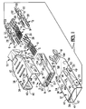
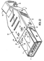
- shielding 36 for the electrical connector comprises; two conductive, telescopic shells 37, 38 that fit and slide one within the other.
- Each of the shells 37, 38 is of unitary construction, stamped and formed from a metal plate.
- the shells 37, 38 each are bent on themselves, forming wrapped sections, and forming telescopic first and second tubular enclosures 39, 40 , with open front ends 41, 42 and open rear ends 43, 44 , which fit slidably one within another.
- a longitudinal seam 45 in the enclosure 39 of the first shell 37 intersects and extends through the front and rear ends 41 and 43.
- a similar longitudinal gap 46 in the enclosure 40 intersects and extends through the front and rear ends 42 and 44.
- the gap 46 of the second shell 38 is open, by a substantial width.
- the seam 45, and the gap 46 of each enclosure 39, 40 are opposite a seamless wall of the same enclosure 39, 40.
- the seam 45, and the gap 46 of each enclosure 39, 40 respectively, fit slidably and telescopically against the seamless wall of the other enclosure 39, 40.
- the open front end 41 on the first shell 37 is the mating end of the shielding 36.
- the seam 45 in the first shell 37 is enveloped by the second shell 38 by telescopic fit to resist widening of the seam 45, and consequent deformation of the mating end 41. Such deformation is undesired, for it would create frictional resistance to mating connection of the connector 1 to another, mating connector, and would resist conforming fit of the shielding 36 with and against shielding on the mating connector.
- a number of folds 47 in the tubular enclosure 39 conform to a chamfered exterior shape of the housing 2 of the connector 1.
- the folds 47 define the circumference of the profile on the mating end 41.
- Notches 22 extend forwardly from the rear end 43 and in alignment with chamfers 23 defined by the folds 47.
- the notches 22 end in rear facing shoulders 24 .
- Folds 47 in the enclosure 40 define the circumferences of the open ends 42, 44.
- the folds 47 conform the shell 38 with the shape of the first shell 37.
- Multiple locks 48 in the form of openings, located on both sides of the seam 45, lock to the connector 1 by locking to the projecting locks 34 on the housing 2.
- the cable 25 is terminated with the connector 1, and the connector 1 is inserted into the open rear end 43 of the first enclosure 39, and is slidable along the enclosure 39 until the projecting locks 34 on the housing 2 emerge in, and lock with, the locks 48 of the first shell 37, Figure 4.
- the first shell 37 locks onto the connector 1, to resist shifting of the connector 1 rearward relative to a mating end 41 of the shielding 36, especially during mating connection of the connector 1 with another, mating connector.
- the front facing shoulders 21 face the rear facing shoulders 24 to resist further forward movement of the housing 2 relative to the shell 37.
- the first shell 37 locks onto the housing 2 on both sides of the seam 45, further to resist widening of the seam 45.
- the first and second shells 37, 38 interlock with one another along both sides of the seam 45, to resist widening of the seam 45.
- Projecting locks 49 on the exterior of the enclosure 39 of the first shell 37 are in the form of inclined wedge projections, having outlines cut from the shell 37, tapering toward the rear open end 43.
- Locks 50 in the form of openings in the enclosure 40 of the second shell 38, are aligned with the locks 49 of the first shell 37.
- Deformable strain relief portions 51, 52 at the rear of the first and second shells 37, 38 are deformable together to grip the cable 25.
- the strain relief portion 52 comprises, a channel 53 with clamping fingers 54 extending from a base of the channel 53.
- the strain relief portion 51 comprises, a channel 55 with an external indentation 56 in a base of the channel 55.
- the deformable strain relief portions 51, 52 initially are bent obliquely outward, Figures 2 and 3, providing clearance to receive the cable 25 in both channels 53, 55 that overlap each other, Figure 5.
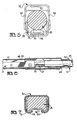
- strain relief portions 51, 52 are straightened, Figure 7 to clamp the cable 25 and reshape the cross section of the cable 25 to fit and conform within the channels 53, 55.
- the clamping fingers 54 are closed toward each other and enter the indentation 56.
- an overmold 57 Figure 8, in the form of a molded insulation of desired shape, covers and adheres to the cable 25 and the strain relief portions 51, 52.
- the mating end 41 and a deformable strain relief portion 51 are connected at opposite ends of an interposed tongue 58 .
- the tongue 58 separates the enclosure 39 from the strain relief portion 51, and isolates the enclosure 39 from distortion which might result because of deformation of the strain relief portion 51.
- the first shell 37 provides a deformable portion 51 of the strain relief subject to being deformed over a cable 25, and a mating end 41 at a front of the shielding 36 having a shaped profile that remains undistorted by deformation of the -deformable portion 51, due to the interposed tongue 58.
- the tongue 58 extends along the second shell 38 from front to rear. Further, the tongue 58 extends inside the second shell 38, and covers the open seam 46 of the second shell 38.
- the tongue 58 tapers toward the rear to a narrow section 60 adjacent to the strain relief portion 51.
- Flanges 59 on the second shell 38 face each other across the gap 46 and overlap the tongue 58.
- the flanges 59 each are notched at 61 , which allows the flanges 59 to change direction and converge toward each other adjacent to the strain relief portion 52, thereby tapering the width of the open gap 46.
- the narrow section 60 is narrower that the width of the open gap 46 at the front of the second shell 38.
- the second shell 38 is assembled to the first shell 37, first by inserting the narrow section 60 into the front of the open gap 46, then, sliding the flanges 59 over the narrow section 60 and forwardly.
- the converging portions of the flanges 59 overlap the tapered tongue 58, and resist further forward movement of the rear shell 38.
- the enclosures 39, 40 of the shells 37, 38 slidably fit one into the other.
- the projecting locks 49 of the first shell 37 enter and lock with the locks 50 of the second shell 38, and resist rearward movement of the second shell 38.
- the second shell 38 has inward projecting tabs 62, Figure 4, having outlines cut from the shell 38, that engage behind the rear end 43 of the first shell 37 to resist rearward movement of the first shell 37. Thereby, the shells 37, 38 lock to each other.
- An advantage of the present invention is a shielded electrical connector wherein seams of telescopically fitted shells of shield members disposed onto an electrical connector are enveloped by seamless walls of the shells. Another advantage of the invention is the locks of the shells and the connector resist widening of the seam so that a matable end of the shell is easily matable with a matable connector. A further advantage of the invention is the provision of strain relief portions on the shells for engagement with an electrical cable.
Landscapes
- Details Of Connecting Devices For Male And Female Coupling (AREA)
Claims (7)
- Connecteur électrique blindé.a) comprenant une connecteur électrique (1), comportantaa) des contacts électriques (3, 4), fixés dans un boítier diélectrique (2),ab) les contacts électriques (3, 6) pouvant être connectés électriquement à des conducteurs électriques (27, 30) d'un câble électrique (25), etac) des éléments de blindage (37, 38), montés sur le connecteur électrique (1), englobant des parties de décharge de traction (51, 52) au niveau des extrémités arrière correspondantes, déformables sur le câble électrique (25),b) lesdits éléments de blindage (37, 38) comprenant des enveloppes (37, 38) ajustées téléscopiquement l'une dans l'autre et glissant l'une dans l'autre vers l'avant des extrémités arrière correspondantes,c) une jointure (45) d'une des enveloppes (37) étant enveloppée par l'autre des enveloppes (38) pour résister à un élargissement de ladite jointure.
- Connecteur électrique blindé selon la revendication 1, dans lequel une desdites enveloppes (37) comporte des verrous (48) accouplés aux verrous (34) sur ledit connecteur (1) pour y retenir l'enveloppe.
- Connecteur électrique blindé selon les revendications 1 ou 2, dans lequel les enveloppes (37, 38) comportent des verrous (49, 50) pour maintenir assemblées les enveloppes.
- Connecteur électrique blindé selon les revendications 2 ou 3, dans lequel les verrous (34, 48, 49, 50) sont agencés sur les deux côtés de la jointure (45) pour résister à un élargissement de la jointure.
- Connecteur électrique blindé selon l'une quelconque des revendications 1 à 4, dans lequel la jointure (45) de l'une des enveloppes (37) fait face à une paroi sans joints de l'autre des enveloppes (38), un espace (46) de l'autre des enveloppes (30) étant orienté vers une paroi sans joints de l'une des enveloppes.
- Connecteur électrique blindé selon l'une quelconque des revendications 1 à 5, dans lequel une desdites enveloppes (37) englobe une languette (58) avec une section tubulaire au niveau d'une extrémité et une partie de décharge de traction au niveau de l'autre extrémité.
- Connecteur électrique blindé selon les revendications 5 ou 6, dans lequel ladite jointure (45) de l'une des enveloppes (37) est étroite et ledit espace (46) de l'autre des enveloppes (38) est large.
Applications Claiming Priority (2)
| Application Number | Priority Date | Filing Date | Title |
|---|---|---|---|
| US8926 | 1993-01-26 | ||
| US08/008,926 US5518421A (en) | 1993-01-26 | 1993-01-26 | Two piece shell for a connector |
Publications (3)
| Publication Number | Publication Date |
|---|---|
| EP0608813A2 EP0608813A2 (fr) | 1994-08-03 |
| EP0608813A3 EP0608813A3 (fr) | 1995-05-17 |
| EP0608813B1 true EP0608813B1 (fr) | 1999-04-14 |
Family
ID=21734528
Family Applications (1)
| Application Number | Title | Priority Date | Filing Date |
|---|---|---|---|
| EP94100995A Expired - Lifetime EP0608813B1 (fr) | 1993-01-26 | 1994-01-24 | Boíte à deux pièces pour un connecteur |
Country Status (6)
| Country | Link |
|---|---|
| US (1) | US5518421A (fr) |
| EP (1) | EP0608813B1 (fr) |
| JP (1) | JP3354269B2 (fr) |
| KR (1) | KR100212589B1 (fr) |
| CN (1) | CN1076895C (fr) |
| DE (1) | DE69417780T2 (fr) |
Families Citing this family (102)
| Publication number | Priority date | Publication date | Assignee | Title |
|---|---|---|---|---|
| TW286443B (fr) * | 1994-10-25 | 1996-09-21 | Fridolin Alois Frech | |
| WO1996030971A1 (fr) * | 1995-03-27 | 1996-10-03 | The Whitaker Corporation | Systeme de blindage pour un connecteur electrique |
| US5788537A (en) * | 1995-03-27 | 1998-08-04 | The Whiteker Corporation | Shield assembly for an electrical connector |
| US5683269A (en) * | 1995-03-27 | 1997-11-04 | The Whitaker Corporation | Shielded electrical connector with cable strain relief |
| USD378209S (en) * | 1995-03-29 | 1997-02-25 | Sony Corporation | Plug for cable connector |
| US5700164A (en) * | 1995-06-16 | 1997-12-23 | The Whitaker Corporation | Electrical connector with shield |
| USD378912S (en) * | 1995-09-25 | 1997-04-22 | Sega Enterprises, Ltd. | Connector |
| US5738544A (en) * | 1996-06-27 | 1998-04-14 | The Whitaker Corporation | Shielded electrical connector |
| US5755595A (en) * | 1996-06-27 | 1998-05-26 | Whitaker Corporation | Shielded electrical connector |
| US5944559A (en) * | 1996-06-29 | 1999-08-31 | Hon Hai Precision Ind. Co., Ltd. | Shielded electrical connector |
| US5725395A (en) * | 1996-08-12 | 1998-03-10 | Lee; Su-Lan Yang | Universal serial bus connector |
| US5899772A (en) * | 1997-02-26 | 1999-05-04 | The Whitaker Corporation | Shielding for an electrical connector |
| TW335229U (en) * | 1997-03-21 | 1998-06-21 | Hon Hai Prec Ind Co Ltd | Plug connector |
| TW321372U (en) * | 1997-05-16 | 1997-11-21 | Molex Taiwan Co Ltd | Electrical connector to block the EMI (Electromagnetic Interference) |
| US6074251A (en) * | 1997-06-09 | 2000-06-13 | The Siemon Company | Shielded high density patch panel |
| CN1088273C (zh) * | 1997-07-16 | 2002-07-24 | 鸿海精密工业股份有限公司 | 连接器遮蔽装置 |
| NO983246L (no) * | 1997-09-29 | 1999-03-30 | Siemens Ag | Kabelst°psel med jordingskontakt |
| US6077122A (en) * | 1997-10-30 | 2000-06-20 | Thomas & Bett International, Inc. | Electrical connector having an improved connector shield and a multi-purpose strain relief |
| US5934942A (en) * | 1997-12-30 | 1999-08-10 | Molex Incorporated | Shielded electrical connector assembly |
| US6328601B1 (en) * | 1998-01-15 | 2001-12-11 | The Siemon Company | Enhanced performance telecommunications connector |
| US6780054B2 (en) | 1998-01-15 | 2004-08-24 | The Siemon Company | Shielded outlet having contact tails shield |
| US6017245A (en) * | 1998-08-19 | 2000-01-25 | Amphenol Corporation | Stamped backshell assembly with integral front shield and rear cable clamp |
| TW392939U (en) * | 1998-09-02 | 2000-06-01 | Molex Inc | Connector fixture |
| JP3229272B2 (ja) * | 1998-10-21 | 2001-11-19 | ヒロセ電機株式会社 | シールドコネクタ |
| USD424522S (en) * | 1998-12-18 | 2000-05-09 | Mitsumi Electric Co., Ltd. | Electric connector |
| ATE263444T1 (de) * | 1999-01-22 | 2004-04-15 | Siemon Co | Telekommunikationsverbinder |
| US6227910B1 (en) * | 1999-02-03 | 2001-05-08 | Hon Hai Precision Ind. Co., Ltd. | EMI shield |
| US6062907A (en) * | 1999-02-04 | 2000-05-16 | Hon Hai Precision Ind. Co., Ltd. | Offset ultra SCSI connector |
| SG80022A1 (en) * | 1999-04-13 | 2001-04-17 | Molex Inc | Shielded electrical connector |
| TW417859U (en) * | 1999-06-15 | 2001-01-01 | Hon Hai Prec Ind Co Ltd | Electric connector of easily automatic assembling |
| US6186828B1 (en) * | 1999-08-30 | 2001-02-13 | Molex Incorporated | Electrical connector including coaxial cable management system |
| US6524135B1 (en) * | 1999-09-20 | 2003-02-25 | 3M Innovative Properties Company | Controlled impedance cable connector |
| JP2001135421A (ja) * | 1999-11-05 | 2001-05-18 | Matsushita Electric Works Ltd | テレビコンセント |
| JP2001273947A (ja) * | 2000-03-28 | 2001-10-05 | Matsushita Electric Ind Co Ltd | 接続ケーブル |
| CN2419700Y (zh) * | 2000-03-29 | 2001-02-14 | 杨泰和 | 具有与电磁波隔离壳体隔离结构的导电连接接口装置、 |
| US6434316B1 (en) * | 2000-06-23 | 2002-08-13 | Molex Incorporated | Fiber optic connector |
| JP2002298985A (ja) * | 2001-03-30 | 2002-10-11 | Mitsumi Electric Co Ltd | コネクタ |
| US6402552B1 (en) | 2001-08-07 | 2002-06-11 | Fci Americas Technology, Inc. | Electrical connector with overmolded and snap locked pieces |
| EP1461846B1 (fr) * | 2002-01-07 | 2005-08-17 | Molex Incorporated | Connecteur automobile a capacite de retenue amelioree |
| US6695641B1 (en) * | 2002-12-24 | 2004-02-24 | Hon Hai Precision Ind. Co., Ltd. | Cable connector assembly |
| US6648676B1 (en) * | 2002-12-24 | 2003-11-18 | Hon Hai Precision Ind. Co., Ltd. | Cable end connector assembly |
| TW555245U (en) * | 2003-01-29 | 2003-09-21 | Hon Hai Prec Ind Co Ltd | Cable connector assembly |
| US6821160B2 (en) * | 2003-04-01 | 2004-11-23 | Delphi Technologies, Inc. | High voltage electrical connection |
| USD491894S1 (en) | 2003-05-02 | 2004-06-22 | Hon Hai Precision Ind. Co., Ltd. | Cable connector assembly |
| TWM244615U (en) * | 2003-10-15 | 2004-09-21 | Comax Technology Inc | External high-frequency connector |
| TWM251379U (en) * | 2004-02-11 | 2004-11-21 | Comax Technology Inc | Grounding structure of electrical connector |
| USD510725S1 (en) * | 2004-04-21 | 2005-10-18 | Cheng Uei Precision Industry Co., Ltd. | Plug connector |
| KR100623284B1 (ko) * | 2004-06-25 | 2006-09-19 | 케이. 에이. 이 (주) | 이동통신 단말기용 플러그 커넥터 |
| JP2006256448A (ja) * | 2005-03-16 | 2006-09-28 | Tyco Electronics Amp Kk | 自動車用コネクタ組立体 |
| US20070036489A1 (en) * | 2005-08-15 | 2007-02-15 | Barbara Grzegorzewska | Industrial interconnect system incorporating transceiver module cage |
| SE529718C2 (sv) * | 2006-03-09 | 2007-11-06 | Plastab I Anderstorp Ab | Kontaktfinger med räfflor |
| TWM312071U (en) * | 2006-11-15 | 2007-05-11 | Long Chang Technology Co Ltd | Metal case structure of USB connector |
| KR100829237B1 (ko) * | 2007-03-08 | 2008-05-14 | 케이. 에이. 이 (주) | 이동통신단말기용 커넥터 소켓 |
| US7765695B2 (en) * | 2007-05-29 | 2010-08-03 | Channell Commercial Corporation | Method and process for manufacturing a terminal block |
| US7625243B2 (en) * | 2007-06-13 | 2009-12-01 | Hon Hai Precision Ind. Co., Ltd. | Extension to version 2.0 universal serial bus connector with improved contact arrangement |
| JP4999175B2 (ja) * | 2007-10-03 | 2012-08-15 | 矢崎総業株式会社 | シールドコネクタ |
| US7465194B1 (en) * | 2007-12-27 | 2008-12-16 | Cheng Uei Precision Industry Co., Ltd. | Plug connector |
| JP5039690B2 (ja) * | 2008-12-25 | 2012-10-03 | ホシデン株式会社 | 多極コネクタ |
| US9685259B2 (en) | 2009-06-19 | 2017-06-20 | 3M Innovative Properties Company | Shielded electrical cable |
| WO2010148165A2 (fr) | 2009-06-19 | 2010-12-23 | 3M Innovative Properties Company | Câble électrique blindé |
| TWI458204B (zh) * | 2009-07-29 | 2014-10-21 | Hon Hai Prec Ind Co Ltd | 電連接器 |
| CN101989704B (zh) * | 2009-08-04 | 2013-12-25 | 富士康(昆山)电脑接插件有限公司 | 电连接器 |
| DE102010002681B4 (de) * | 2010-03-09 | 2018-10-18 | Te Connectivity Germany Gmbh | Elektrischer Steckverbinder, elektrische Steckverbindung sowie konfektioniertes elektrisches Kabel |
| TWM389380U (en) * | 2010-05-19 | 2010-09-21 | Advanced Connectek Inc | Miniature high frequency plug connector |
| RU2544839C2 (ru) | 2010-05-28 | 2015-03-20 | Эппл Инк. | Соединитель с двойной ориентацией с внешними контактами |
| JP5629495B2 (ja) * | 2010-06-01 | 2014-11-19 | ホシデン株式会社 | コネクタ |
| CN102884592B (zh) | 2010-08-31 | 2017-12-26 | 3M创新有限公司 | 具有电介质间距的屏蔽电缆 |
| US10147522B2 (en) | 2010-08-31 | 2018-12-04 | 3M Innovative Properties Company | Electrical characteristics of shielded electrical cables |
| EP2889881A1 (fr) | 2010-08-31 | 2015-07-01 | 3M Innovative Properties Company | Câble électrique blindé |
| CA2809347A1 (fr) | 2010-08-31 | 2012-03-08 | 3M Innovative Properties Company | Cable electrique blinde en configuration twinaxiale |
| BR112013003296A2 (pt) | 2010-08-31 | 2016-06-07 | 3M Innovatie Properties Company | cabo elétrico blindado e montagem de cabo |
| US12205732B2 (en) | 2010-08-31 | 2025-01-21 | 3M Innovative Properties Company | Shielded electric cable |
| BR112013003830A2 (pt) | 2010-08-31 | 2019-09-24 | 3M Innovative Properties Co | ''cabo elétrico blindado de alta densidade e outros cabos blindados,sistemas e métodos'' |
| WO2012039736A1 (fr) | 2010-09-23 | 2012-03-29 | 3M Innovative Properties Company | Câble électrique blindé |
| JP5680435B2 (ja) | 2011-02-14 | 2015-03-04 | 矢崎総業株式会社 | シールドコネクタの係止構造 |
| JP5771094B2 (ja) * | 2011-08-25 | 2015-08-26 | 矢崎総業株式会社 | シールドコネクタ |
| DE102011082806A1 (de) | 2011-09-16 | 2013-03-21 | Zf Friedrichshafen Ag | Verfahren und Vorrichtung zur Diagnose von Fehlern in Bauteilen von Fahrwerksystemen von Kraftfahrzeugen |
| US8708745B2 (en) | 2011-11-07 | 2014-04-29 | Apple Inc. | Dual orientation electronic connector |
| US9293876B2 (en) | 2011-11-07 | 2016-03-22 | Apple Inc. | Techniques for configuring contacts of a connector |
| US9112327B2 (en) | 2011-11-30 | 2015-08-18 | Apple Inc. | Audio/video connector for an electronic device |
| US8517765B2 (en) * | 2011-12-08 | 2013-08-27 | Tyco Electronics Corporation | Cable header connector |
| EP2792027A4 (fr) * | 2011-12-14 | 2015-09-09 | Intel Corp | Connecteur a taux extensible pour applications grand public a bande passante elevee |
| US8475212B1 (en) * | 2012-02-21 | 2013-07-02 | Cheng Uei Precision Industry Co., Ltd. | Charging connector |
| JP5367121B2 (ja) * | 2012-05-09 | 2013-12-11 | 日本航空電子工業株式会社 | コネクタ |
| US20140030930A1 (en) * | 2012-07-25 | 2014-01-30 | Hon Hai Precision Industry Co., Ltd. | Electrical connector |
| US9093803B2 (en) * | 2012-09-07 | 2015-07-28 | Apple Inc. | Plug connector |
| US9059531B2 (en) | 2012-09-11 | 2015-06-16 | Apple Inc. | Connectors and methods for manufacturing connectors |
| WO2014040231A1 (fr) | 2012-09-11 | 2014-03-20 | Apple Inc. | Connecteurs et procédés pour fabriquer des connecteurs |
| US9160129B2 (en) * | 2012-09-11 | 2015-10-13 | Apple Inc. | Connectors and methods for manufacturing connectors |
| US9325097B2 (en) | 2012-11-16 | 2016-04-26 | Apple Inc. | Connector contacts with thermally conductive polymer |
| US20140206209A1 (en) | 2013-01-24 | 2014-07-24 | Apple Inc. | Reversible usb connector |
| CN108463925A (zh) * | 2016-01-13 | 2018-08-28 | 株式会社自动网络技术研究所 | 连接器 |
| JP6961409B2 (ja) * | 2017-07-12 | 2021-11-05 | ヒロセ電機株式会社 | かしめ構造を有するケーブルコネクタ |
| TWI642237B (zh) * | 2017-10-06 | 2018-11-21 | 唐虞企業股份有限公司 | 電連接器總成及其板端連接器與線端連接器 |
| JP6943175B2 (ja) * | 2017-12-26 | 2021-09-29 | 住友電装株式会社 | 端子金具及びコネクタ |
| KR102056934B1 (ko) | 2018-09-14 | 2020-01-22 | 한국단자공업 주식회사 | 쉴드쉘과 와이어 조립체 및 이를 사용한 고전압 커넥터 |
| JP7089674B2 (ja) | 2018-12-28 | 2022-06-23 | 株式会社オートネットワーク技術研究所 | 端子付き電線およびコネクタ |
| EP3783755B1 (fr) * | 2019-08-20 | 2022-11-02 | Aptiv Technologies Limited | Ensemble comprenant un connecteur et un câble |
| JP6940026B1 (ja) * | 2020-06-02 | 2021-09-22 | 住友電気工業株式会社 | コネクタ付き多心ケーブル |
| EP4238191A4 (fr) * | 2021-01-05 | 2025-01-22 | Outdoor Wireless Networks LLC | Ensemble connecteur coaxial couplé |
| JP7779843B2 (ja) * | 2021-04-01 | 2025-12-03 | ジェイ.エス.ティー.コーポレーション | 少なくとも1つの導電性タブを備え、内部にシールばねを収容する導電性の外側ハウジングを有する高電圧コネクタアセンブリのための、電磁干渉(emi)保護方法 |
| DE102024112725A1 (de) * | 2024-05-06 | 2025-11-06 | Kromberg & Schubert Automotive Gmbh & Co. Kg | Geschirmter Steckverbinder, Steckverbinderanordnung und Montageverfahren der Steckverbinderanordnung |
Citations (1)
| Publication number | Priority date | Publication date | Assignee | Title |
|---|---|---|---|---|
| EP0562311A2 (fr) * | 1992-03-25 | 1993-09-29 | Hosiden Corporation | Connecteur électrique multipolaire à fiches |
Family Cites Families (21)
| Publication number | Priority date | Publication date | Assignee | Title |
|---|---|---|---|---|
| US518481A (en) * | 1894-04-17 | Electrical contact mechanism | ||
| US3760335A (en) * | 1971-05-27 | 1973-09-18 | Amp Inc | Pre-loaded electric connector |
| US4453798A (en) * | 1982-06-18 | 1984-06-12 | Amp Incorporated | Shielded cable on coaxial connector |
| US4653836A (en) * | 1983-07-06 | 1987-03-31 | Amp Incorporated | Shielded electrical connector |
| US4889503A (en) * | 1984-01-16 | 1989-12-26 | Stewart Stamping Corporation | Shielded plug and jack connector |
| US4585292A (en) * | 1984-05-04 | 1986-04-29 | Amp Incorporated | Overmolded shielded connector |
| JPH0239344Y2 (fr) * | 1986-02-21 | 1990-10-22 | ||
| US4974075A (en) * | 1987-08-11 | 1990-11-27 | Olympus Optical Co., Ltd. | Image pickup apparatus having connector capable of separately shielding grouped electrical connections |
| JPH0748387B2 (ja) * | 1987-10-19 | 1995-05-24 | 矢崎総業株式会社 | コネクタ |
| JPH01315968A (ja) * | 1988-03-07 | 1989-12-20 | Hirose Electric Co Ltd | 電気コネクタ |
| US4872736A (en) * | 1988-04-19 | 1989-10-10 | American Telephone And Telegraph Company, At&T Bell Laboratories | Connector assembly having a latching mechanism |
| JPH0622942Y2 (ja) * | 1989-02-28 | 1994-06-15 | ホシデン株式会社 | コネクタ |
| JPH0733403Y2 (ja) * | 1989-12-04 | 1995-07-31 | ホシデン株式会社 | コネクタ |
| JPH0722064Y2 (ja) * | 1989-12-04 | 1995-05-17 | ホシデン株式会社 | コネクタ |
| US5030114A (en) * | 1990-04-30 | 1991-07-09 | International Business Machines Corporation | Shield overcoat |
| US5092794A (en) * | 1990-12-24 | 1992-03-03 | Molex Incorporated | Shielded electrical connector |
| US5180316A (en) * | 1991-03-25 | 1993-01-19 | Molex Incorporated | Shielded electrical connector |
| US5171161A (en) * | 1991-05-09 | 1992-12-15 | Molex Incorporated | Electrical connector assemblies |
| US5087210A (en) * | 1991-06-21 | 1992-02-11 | Amp Incorporated | Wire-to-wire electrical connecting means |
| JP2598584Y2 (ja) * | 1991-09-12 | 1999-08-16 | 矢崎総業株式会社 | 組立式シールドコネクタ |
| US5158481A (en) * | 1991-09-27 | 1992-10-27 | Amp Incorporated | Shielded electrical connector with torsioned shield interconnect |
-
1993
- 1993-01-26 US US08/008,926 patent/US5518421A/en not_active Expired - Lifetime
-
1994
- 1994-01-07 KR KR1019940000197A patent/KR100212589B1/ko not_active Expired - Fee Related
- 1994-01-24 DE DE69417780T patent/DE69417780T2/de not_active Expired - Fee Related
- 1994-01-24 EP EP94100995A patent/EP0608813B1/fr not_active Expired - Lifetime
- 1994-01-25 CN CN94100699A patent/CN1076895C/zh not_active Expired - Fee Related
- 1994-01-26 JP JP02374994A patent/JP3354269B2/ja not_active Expired - Lifetime
Patent Citations (1)
| Publication number | Priority date | Publication date | Assignee | Title |
|---|---|---|---|---|
| EP0562311A2 (fr) * | 1992-03-25 | 1993-09-29 | Hosiden Corporation | Connecteur électrique multipolaire à fiches |
Also Published As
| Publication number | Publication date |
|---|---|
| CN1076895C (zh) | 2001-12-26 |
| JPH06243933A (ja) | 1994-09-02 |
| CN1092562A (zh) | 1994-09-21 |
| JP3354269B2 (ja) | 2002-12-09 |
| EP0608813A2 (fr) | 1994-08-03 |
| DE69417780T2 (de) | 1999-11-11 |
| EP0608813A3 (fr) | 1995-05-17 |
| KR100212589B1 (ko) | 1999-08-02 |
| US5518421A (en) | 1996-05-21 |
| DE69417780D1 (de) | 1999-05-20 |
Similar Documents
| Publication | Publication Date | Title |
|---|---|---|
| EP0608813B1 (fr) | Boíte à deux pièces pour un connecteur | |
| US5785557A (en) | Electrical connector with protection for electrical contacts | |
| EP0753213B1 (fr) | Agencement de blindage pour connecteur electrique avec une enveloppe arriere de blindage | |
| US4737118A (en) | Hermaphroditic flat cable connector | |
| EP1003250B1 (fr) | Un connecteur blindé, un jeu de connecteurs blindés et procédé pour connecter un connecteur blindé avec un câble blindé | |
| US5888100A (en) | Twisted pair cable and connector assembly | |
| US5865646A (en) | Connector shield with integral latching and ground structure | |
| US4682840A (en) | Electrical connection and method of making same | |
| US4602831A (en) | Electrical connector and method of making same | |
| US4398780A (en) | Shielded electrical connector | |
| JPH0521110A (ja) | シールド型電気コネクタ | |
| JPH0828252B2 (ja) | 電気コネクタ組立体及びその製造方法 | |
| CA1198789A (fr) | Prise d'electricite | |
| JPH05275129A (ja) | ケーブルクランプ装置 | |
| JPH07106003A (ja) | モジュラー式同軸ケーブルコネクター及びそのアッセンブリ方法 | |
| EP0125760A1 (fr) | Connecteur à broches ayant une enveloppe blindée | |
| US6811450B1 (en) | Electrical receptacle-type terminal | |
| EP0401040A2 (fr) | Connecteur électrique pour prise "S" d'installation vidéo | |
| US5975955A (en) | Shielded electrical connector assembly with grounding system | |
| US6309250B1 (en) | Coaxial connector termination | |
| EP0021785A1 (fr) | Assemblage de connecteurs électriques à connecteurs mâle et femelle serrés ensemble | |
| US7354294B2 (en) | Coaxial cable connector, and harness unit that utilizes the coaxial cable connector | |
| EP0534276B1 (fr) | Organe de contact à déplacement d'isolation pour connecteur électrique | |
| GB2261777A (en) | Pole holding member for an electrical connector | |
| EP1003244B1 (fr) | Connecteur blindé et procedé pour connecter un connecteur blindé avec un câble blindé |
Legal Events
| Date | Code | Title | Description |
|---|---|---|---|
| PUAI | Public reference made under article 153(3) epc to a published international application that has entered the european phase |
Free format text: ORIGINAL CODE: 0009012 |
|
| AK | Designated contracting states |
Kind code of ref document: A2 Designated state(s): DE FR GB IT NL |
|
| PUAL | Search report despatched |
Free format text: ORIGINAL CODE: 0009013 |
|
| AK | Designated contracting states |
Kind code of ref document: A3 Designated state(s): DE FR GB IT NL |
|
| 17P | Request for examination filed |
Effective date: 19951116 |
|
| 17Q | First examination report despatched |
Effective date: 19960828 |
|
| GRAG | Despatch of communication of intention to grant |
Free format text: ORIGINAL CODE: EPIDOS AGRA |
|
| GRAG | Despatch of communication of intention to grant |
Free format text: ORIGINAL CODE: EPIDOS AGRA |
|
| GRAH | Despatch of communication of intention to grant a patent |
Free format text: ORIGINAL CODE: EPIDOS IGRA |
|
| GRAH | Despatch of communication of intention to grant a patent |
Free format text: ORIGINAL CODE: EPIDOS IGRA |
|
| GRAA | (expected) grant |
Free format text: ORIGINAL CODE: 0009210 |
|
| AK | Designated contracting states |
Kind code of ref document: B1 Designated state(s): DE FR GB IT NL |
|
| PG25 | Lapsed in a contracting state [announced via postgrant information from national office to epo] |
Ref country code: NL Free format text: LAPSE BECAUSE OF FAILURE TO SUBMIT A TRANSLATION OF THE DESCRIPTION OR TO PAY THE FEE WITHIN THE PRESCRIBED TIME-LIMIT Effective date: 19990414 Ref country code: IT Free format text: LAPSE BECAUSE OF FAILURE TO SUBMIT A TRANSLATION OF THE DESCRIPTION OR TO PAY THE FEE WITHIN THE PRESCRIBED TIME-LIMIT;WARNING: LAPSES OF ITALIAN PATENTS WITH EFFECTIVE DATE BEFORE 2007 MAY HAVE OCCURRED AT ANY TIME BEFORE 2007. THE CORRECT EFFECTIVE DATE MAY BE DIFFERENT FROM THE ONE RECORDED. Effective date: 19990414 |
|
| REF | Corresponds to: |
Ref document number: 69417780 Country of ref document: DE Date of ref document: 19990520 |
|
| ET | Fr: translation filed | ||
| NLV1 | Nl: lapsed or annulled due to failure to fulfill the requirements of art. 29p and 29m of the patents act | ||
| PLBE | No opposition filed within time limit |
Free format text: ORIGINAL CODE: 0009261 |
|
| STAA | Information on the status of an ep patent application or granted ep patent |
Free format text: STATUS: NO OPPOSITION FILED WITHIN TIME LIMIT |
|
| 26N | No opposition filed | ||
| REG | Reference to a national code |
Ref country code: GB Ref legal event code: IF02 |
|
| PGFP | Annual fee paid to national office [announced via postgrant information from national office to epo] |
Ref country code: FR Payment date: 20060117 Year of fee payment: 13 |
|
| PGFP | Annual fee paid to national office [announced via postgrant information from national office to epo] |
Ref country code: GB Payment date: 20060119 Year of fee payment: 13 |
|
| PGFP | Annual fee paid to national office [announced via postgrant information from national office to epo] |
Ref country code: DE Payment date: 20060228 Year of fee payment: 13 |
|
| PG25 | Lapsed in a contracting state [announced via postgrant information from national office to epo] |
Ref country code: DE Free format text: LAPSE BECAUSE OF NON-PAYMENT OF DUE FEES Effective date: 20070801 |
|
| GBPC | Gb: european patent ceased through non-payment of renewal fee |
Effective date: 20070124 |
|
| REG | Reference to a national code |
Ref country code: FR Ref legal event code: ST Effective date: 20070930 |
|
| PG25 | Lapsed in a contracting state [announced via postgrant information from national office to epo] |
Ref country code: GB Free format text: LAPSE BECAUSE OF NON-PAYMENT OF DUE FEES Effective date: 20070124 |
|
| PG25 | Lapsed in a contracting state [announced via postgrant information from national office to epo] |
Ref country code: FR Free format text: LAPSE BECAUSE OF NON-PAYMENT OF DUE FEES Effective date: 20070131 |