EP0609841A2 - Optische Verbindung mit Klebstoff - Google Patents
Optische Verbindung mit Klebstoff Download PDFInfo
- Publication number
- EP0609841A2 EP0609841A2 EP94101480A EP94101480A EP0609841A2 EP 0609841 A2 EP0609841 A2 EP 0609841A2 EP 94101480 A EP94101480 A EP 94101480A EP 94101480 A EP94101480 A EP 94101480A EP 0609841 A2 EP0609841 A2 EP 0609841A2
- Authority
- EP
- European Patent Office
- Prior art keywords
- adhesive
- optical fiber
- optical
- optical connector
- fixing
- Prior art date
- Legal status (The legal status is an assumption and is not a legal conclusion. Google has not performed a legal analysis and makes no representation as to the accuracy of the status listed.)
- Granted
Links
Images
Classifications
-
- G—PHYSICS
- G02—OPTICS
- G02B—OPTICAL ELEMENTS, SYSTEMS OR APPARATUS
- G02B6/00—Light guides; Structural details of arrangements comprising light guides and other optical elements, e.g. couplings
- G02B6/24—Coupling light guides
- G02B6/36—Mechanical coupling means
- G02B6/38—Mechanical coupling means having fibre to fibre mating means
- G02B6/3807—Dismountable connectors, i.e. comprising plugs
- G02B6/3833—Details of mounting fibres in ferrules; Assembly methods; Manufacture
- G02B6/3855—Details of mounting fibres in ferrules; Assembly methods; Manufacture characterised by the method of anchoring or fixing the fibre within the ferrule
- G02B6/3861—Adhesive bonding
-
- G—PHYSICS
- G02—OPTICS
- G02B—OPTICAL ELEMENTS, SYSTEMS OR APPARATUS
- G02B6/00—Light guides; Structural details of arrangements comprising light guides and other optical elements, e.g. couplings
- G02B6/24—Coupling light guides
- G02B6/36—Mechanical coupling means
- G02B6/38—Mechanical coupling means having fibre to fibre mating means
- G02B6/3807—Dismountable connectors, i.e. comprising plugs
- G02B6/3833—Details of mounting fibres in ferrules; Assembly methods; Manufacture
- G02B6/3865—Details of mounting fibres in ferrules; Assembly methods; Manufacture fabricated by using moulding techniques
-
- G—PHYSICS
- G02—OPTICS
- G02B—OPTICAL ELEMENTS, SYSTEMS OR APPARATUS
- G02B6/00—Light guides; Structural details of arrangements comprising light guides and other optical elements, e.g. couplings
- G02B6/24—Coupling light guides
- G02B6/36—Mechanical coupling means
- G02B6/38—Mechanical coupling means having fibre to fibre mating means
- G02B6/3807—Dismountable connectors, i.e. comprising plugs
- G02B6/3873—Connectors using guide surfaces for aligning ferrule ends, e.g. tubes, sleeves, V-grooves, rods, pins, balls
- G02B6/3885—Multicore or multichannel optical connectors, i.e. one single ferrule containing more than one fibre, e.g. ribbon type
Definitions
- This invention relates to an adhesive for adhering and fixing an optical fiber to the optical connector in an optical system, and to an optical connector connected and fixed to the optical fiber by the adhesive.
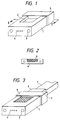
- FIGURE 1 The general shape of an optical connector ferrule, especially a multi-fiber optical connector ferrule, is shown in FIGURE 1.
- a thermosetting epoxy type adhesive 8 is injected into an adhesive injection opening 2.
- one optical fiber cable includes up to 1000 optical fibers.
- the adhesive 8 is hardened at about 80°C so that the optical fiber is fixed to the ferrule 1.
- the end portion of the ferrule is ground to form an optical connector.
- a plurality of fixing pin insert holes 3 are provided for receiving fixing pins to connect to another optical connector.
- FIGURE 2 is a cross sectional view taken along line II-II of FIGURE 1 and wherein the adhesive 8 has been injected into the adhesive injection opening 2.
- the adhesive needs to have a low viscosity to fill up to the end of the optical fiber holes 4 and a high hardness to fix the optical fiber tightly when the ferrule 1 is ground.
- thermosetting epoxy type adhesive used is selected to provide resistance to chemicals or the like.
- the coefficient of linear expansion is from 5.0 x 10 ⁇ 5 to 1.0 x 10 ⁇ 4
- Young's Modulus is from 500 to 1000 kg/mm2
- the hardening temperature is from 60°C to 100 °C
- the filler content is from 0 weight % to 30 weight %
- the viscosity at the hardening temperature is 100 cps to 1000 cps
- the particle diameter of the filler is from 0.1 ⁇ m to 100 ⁇ m
- the rate of hardening shrinkage is 1 % to 5%.
- the conventional adhesive has had the problem(s) that the ferrule may be deformed and that the optical fiber is stressed, thereby increasing light transmission loss, by the shrinkage force of the adhesive during cooling down from the hardening temperature to room temperature, or a shrinkage after hardening.
- the rate of hardening shrinkage and Young's Modulus of the adhesive have to be small to prevent deformation of the ferrule and to minimize stress to the optical fiber.
- the adhesive has to harden at room temperature to prevent deformation of the ferrule.
- Adhesives that harden at room temperature are a silicone type RTV rubber adhesive, UV hardening type adhesive, visible light hardening type adhesive and the like.
- the present invention will be described in detail as follows:
- the value of (the coefficient of linear expansion of the adhesive (°C ⁇ 1)) x (the difference between the hardening temperature of the adhesive and room temperature (°C)) x (Young's Modulus (kg/mm2)) is 2.5 or less.
- a filler is effective to provide an adhesive that has a small coefficient of linear expansion, the filler contributes to an increase in the viscosity of the adhesive.
- the filler content in the adhesive is preferably from about 20 weight % to 70 weight % and the viscosity thereof is preferably from about 50 cps to 2000 cps at a temperature when the optical fiber is adhered to the ferrule.
- a filler having a small diameter which is from about 0.1 ⁇ m to 1.0 ⁇ m so that the adhesive will have a low viscosity, even if it includes the filler.
- the first adhesive of the present invention has a small coefficient of linear expansion and Young's Modulus, it is unlikely that the ferrule will be deformed by a shrinkage force during cooling down or that there will be an increase in the light transmission loss from stress to the optical fiber.
- the value of (the coefficient of linear expansion of the adhesive (°C ⁇ 1)) x (the difference between the hardening temperature of the adhesive and the room temperature (°C)) x (Young's Modulus (kg/mm2)) is 2.5 or less.
- the coefficient of linear expansion of the adhesive is preferably near that of the ferrule material (1x10 ⁇ 5 - 2x10 ⁇ 5), and most preferably less than 4.0x10 ⁇ 5.
- the filler causes the adhesive to have a small coefficient of linear expansion.
- the filler content is preferably from about 20 weight % to 70 weight %. A content of less than about 20 weight % does not contribute to a decrease the coefficient of linear expansion. A content of more than about 70 weight % makes the adhesive too viscous.
- the filler increases the viscosity of the adhesive. Therefore, a spherical filler, the diameter of which is from 0.1 ⁇ m to 1.0 ⁇ m, is preferably used so that the adhesive will have a good fluidity and will flow to the end of an optical fiber insert holes. A diameter of more than 1.0 ⁇ m does not contribute to fluidity. A diameter of less than 0.1 ⁇ m coheres easily.
- the filler included in the first adhesive of the present invention is silica, calcium carbonate, alumina, mica or the like.
- the viscosity of the first adhesive of the present invention is preferably from 50 cps to 2000 cps at the hardening temperature. A viscosity of less than 50 cps is too fluid and is thus difficult to work with. A viscosity of more than 2000 cps does not flow to the end of the optical fiber hole(s).
- the Young's Modulus of the first adhesive is preferably from 100 kg/mm2 to 1000 kg/mm2.
- An adhesive having a Young's Modulus of more than 1000 kg/mm2 stresses the material of the ferrule and causes the optical fiber to deform, thereby increasing the light transmission loss. Further, an adhesive having a Young's Modulus of less than 100 kg/mm2 is too soft to support the optical fiber when the optical connector is ground.
- epoxy type, silicone type, acrylic type and urethane type or like adhesives are preferable as the first adhesive of the present invention.
- inorganic filler, thickener, thixotropy agent, some kinds of fixing agent and the like may be added to an epoxy resin having a predetermined viscosity, for example, EPOTECH, produced by Epoxy Technology Co. Ltd., so that the adhesive has a predetermined coefficient of linear expansion, viscosity and Young's modulus.
- the value of (the harding shrinkage (%))) x (Young's Modulus (kg/mm2) is 1000 or less and, especially, the rate of hardening shrinkage is preferably 1% or less and the Young's Modulus is preferably from 100 kg/mm2 to 1000 kg/mm2. Since the second adhesive of the present invention has a small rate of hardening shrinkage and Young's modulus, it is unlikely that it will deform the ferrule during hardening of the adhesive and or that the adhesive will increase the light transmission loss by stressing the optical fiber.
- the Young's modulus of the second adhesive of the present invention is more than 100 kg/mm2, the ferrule material and the optical fiber are stressed to deform and thus there is an increase in the light transmission loss. Furthermore, if the Young's Modulus of the second adhesive is less than 100 kg/mm2, it too soft and cannot support the optical fiber sufficiently when the optical fiber is ground.
- the adhesive preferably includes a spherical filler the diameter of which is from 0.1 ⁇ m to 1.0 ⁇ m so as to have a good fluidity and to flow to the end of the optical fiber insert holes. A diameter of more than 1.0 ⁇ m does not contribute to fluidity
- a diameter of less than 0.1 ⁇ m coheres too easily. Furthermore, if the filler content is less than about 20 weight %, it is not possible to decrease the hardening shrinkage and the coefficient of linear expansion. If the content is more than about 70 weight %, the adhesive is too viscous.
- Silica, calcium carbonate, alumina, mica or the like are preferable for the filler of the second adhesive of the present invention.
- the viscosity of second adhesive is preferably from 50 cps to 2000 cps at the hardening temperature. If the viscosity is less than 50 cps, the adhesive is too fluid and is thus hard to work with.
- the second adhesive of the present invention is an epoxy type adhesive, silicone type adhesive, acryle type adhesive or the like.
- the third adhesive hardens at room temperature, so that the adhesive does not shrink from temperature changes after hardening. Thus, it is unlikely that the ferrule will deform or that the optical fiber will be stressed so as to increase light transmission loss.
- Adhesives that harden at room temperature are silicone type RTV rubber adhesive, UV hardening type adhesive, visible light hardening type adhesive and the like.
- the silicone type RTV rubber adhesive reacts with water in the air, which is classified as a deacetic acid type, a deoxim type, a dealcohl type, a deacetone type or the like.
- epoxy type adhesives are thermosetting
- an alipaticamine type hardening agent can make it harden at room temperature.
- an adhesive which is hardened by UV light or visible light is an urethane acrylate, epoxy acrylate, silicon acrylate, cyano acrylate or the like.
- the preferred viscosity of the third adhesive is from about 50 cps to 2000 cps. If the viscosity is less than 50 cps, it will be too fluid and hence will be difficult to work with. If the viscosity is more than 2000 cps, it will be too viscous for the optical fiber insert holes to be filled sufficient with the adhesive.
- the preferred Young's Modulus of the third adhesive is 1000 kg/mm2. A Young's Modulus of less than 100 kg/mm2 will be too soft to support and fix the optical fiber during grinding.
- a boot 6 supports the tape-like coated optical fiber.
- An epoxy adhesive 8 two-liquid type thermosetting epoxy adhesive including an aromatic amine hardening agent
- a filler which includes silica was injected form the adhesive injection opening 2 and hardened at 80°C for 1 hour, whereby the optical connector as shown in FIGURE 3 was produced.
- the adhesive having a viscosity of less than 50 cps was too fluid to be able to fix the optical fiber sufficiently. Further, the adhesive having a viscosity of more than 2000 cps could not flow to fill to the end of the optical fiber insert hole(s).
- the adhesive having a filler with a diameter of from 0.1 ⁇ m to 1.0 ⁇ m was used, an optical connector ferrule which has a small deformation volume and little transmission loss after hardening can be produced.
- a four-fiber optical connector ferrule as shown in FIGURE 1, was molded by transfer molding.
- a tape-like coated optical fiber in which four optical fibers were disposed in parallel, was inserted into the ferrule, and each of the eight kinds of epoxy type adhesive indicated in Table II, including a filler comprising a silica, was injected from an adhesive injection opening 2. Thereafter, it was hardened at 80°C for 1 hour so as to adhere and fix an optical fiber. Then, the deformation volume at a wavelength of 1.3 ⁇ m was measured. The results of the measurements are indicated in Table II.
- the adhesive having a viscosity of less than 50 cps was so fluid that it was difficult to fix the optical fiber.
- the adhesive having a viscosity of more than 2000 cps did not flow to the end of the optical fiber insert hole(s).
- a filler the diameter of which was from 0.1 ⁇ m to 1.0 ⁇ m, was used so that the hardening shrinkage was less than 0.1 ⁇ m and the viscosity was less than 2000 cps.
- a four-fiber optical connector ferrule as shown in FIGURE 1, was molded by transfer molding.
- a tape-like coated optical fiber in which four optical fibers were disposed in parallel, was inserted into the ferrule and a silicone type RTV rubber adhesive (viscosity: 1000 cps; Young's Modulus: 100 kg/mm2) was injected from an adhesive injection opening 2. Thereafter, it was hardened at 25°C over 8 hours so as to produce an optical connector shown in FIGURE 3.
- the deformation volume of the adhesive before and after hardening measured by a surface roughness tester was less than 0.1 ⁇ m. Furthermore, the light transmission loss measured at a wavelength of 1.3 ⁇ m was less than 0.1 dB.
- a four-fiber optical connector ferrule as shown in FIGURE 1, was molded by transfer molding as in Embodiment 3-1.
- the deformation volume thereof was less than 0.1 ⁇ m and the light transmission loss thereof was less than 0.2 dB.
- a four-fiber optical connector ferrule as shown in FIGURE 1, was molded by transfer molding, as in Embodiment 3-1.
- the deformation volume thereof was less than 0.1 ⁇ m and the light transmission loss thereof was less than 0.1 dB.
- a four-fiber optical connector ferrule as shown in FIGURE 1 was molded by transfer molding, as in Embodiment 3-1.
- the deformation volume thereof was less than 0.5 ⁇ m and the light transmission loss thereof was less than 0.3 dB.
- the deformation volume of the ferrule after hardening and the stress given to the optical fiber is small.
- the viscosity of the first adhesive during hardening is from 50 cps to 2000 cps so that the adhesive flows to the end of the optical fiber insert holes of the optical connector sufficiently and there are no optical fiber breakage problems during grinding because the adhesive has sufficient hardness.
- the deformation volume of the ferrule during hardening is small and little stress is given to the optical fiber, so as to prevent light transmission loss.
- the filler of the second adhesive has a small diameter and the viscosity thereof is from 50 cps to 2000 cps, the adhesive flows sufficiently to the end of the optical fiber insert holes and has sufficient hardness so that the optical fiber is not broken during grinding.
- the third adhesive for the optical connector of the present invention is hardened at room temperature, there is not ferrule deforming shrinkage as a result of a temperature change after hardening, and the optical fiber is not stressed in a manner that would notably increase the transmission loss.
- the viscosity of the third adhesive is from 50 cps to 2000 cps so as to permit injection of the adhesive sufficiently to the end of the optical fiber insert holes. Since the Young's Modulus of the third adhesive is 100 or more (kg/mm2), the optical fiber is not broken during grinding.
Landscapes
- Physics & Mathematics (AREA)
- General Physics & Mathematics (AREA)
- Optics & Photonics (AREA)
- Mechanical Coupling Of Light Guides (AREA)
- Adhesives Or Adhesive Processes (AREA)
Applications Claiming Priority (9)
| Application Number | Priority Date | Filing Date | Title |
|---|---|---|---|
| JP36187/93 | 1993-02-02 | ||
| JP3618793 | 1993-02-02 | ||
| JP03618793A JP3261786B2 (ja) | 1993-02-02 | 1993-02-02 | 光コネクタ用接着剤及び光コネクタ |
| JP6321293 | 1993-02-26 | ||
| JP06321293A JP3374930B2 (ja) | 1993-02-26 | 1993-02-26 | 光コネクタ用接着剤及び該接着剤を用いた光コネクタ |
| JP63212/93 | 1993-02-26 | ||
| JP87929/93 | 1993-03-22 | ||
| JP8792993 | 1993-03-22 | ||
| JP05087929A JP3141369B2 (ja) | 1993-03-22 | 1993-03-22 | 光コネクタ |
Publications (3)
| Publication Number | Publication Date |
|---|---|
| EP0609841A2 true EP0609841A2 (de) | 1994-08-10 |
| EP0609841A3 EP0609841A3 (de) | 1994-12-28 |
| EP0609841B1 EP0609841B1 (de) | 1999-10-06 |
Family
ID=27289007
Family Applications (1)
| Application Number | Title | Priority Date | Filing Date |
|---|---|---|---|
| EP94101480A Expired - Lifetime EP0609841B1 (de) | 1993-02-02 | 1994-02-01 | Optische Steckerhülse mit Klebstoff-Füllung |
Country Status (5)
| Country | Link |
|---|---|
| US (1) | US5422971A (de) |
| EP (1) | EP0609841B1 (de) |
| CA (1) | CA2114689C (de) |
| DE (1) | DE69420990T2 (de) |
| DK (1) | DK0609841T3 (de) |
Cited By (3)
| Publication number | Priority date | Publication date | Assignee | Title |
|---|---|---|---|---|
| WO1996031572A1 (de) * | 1995-04-03 | 1996-10-10 | Institut für Neue Materialien Gemeinnützige GmbH | Kompositklebstoff für optische und optoelektronische anwendungen |
| WO2000022060A1 (en) * | 1998-10-09 | 2000-04-20 | Minnesota Mining And Manufacturing Company | Optical fiber connector using colored photocurable adhesive |
| EP0994371A3 (de) * | 1998-10-12 | 2004-04-14 | Itt Manufacturing Enterprises, Inc. | Multifaser Verbindungssystem |
Families Citing this family (35)
| Publication number | Priority date | Publication date | Assignee | Title |
|---|---|---|---|---|
| US5602951A (en) * | 1994-04-14 | 1997-02-11 | Sumitomo Electric Industries, Ltd. | Ferrule for optical connector and process for making same |
| CH687621A5 (de) * | 1994-08-12 | 1997-01-15 | Huber+Suhner Ag | Aus wenigstens zwei Komponenten bestehender Klebstoff. |
| US5471555A (en) * | 1994-11-21 | 1995-11-28 | Sumitomo Electric Lightwave Corp. | Fiber optic ribbon break-out device with enhanced strain relief |
| JPH09222536A (ja) * | 1995-12-13 | 1997-08-26 | Furukawa Electric Co Ltd:The | 多心光コネクタ |
| US5619604A (en) * | 1996-02-26 | 1997-04-08 | Alcoa Fujikura Limited | Multi-fiber optical connector |
| US6805493B2 (en) | 1996-03-12 | 2004-10-19 | 3M Innovative Properties Company | Optical connector assembly using partial large diameter alignment features |
| US5778123A (en) * | 1996-03-12 | 1998-07-07 | Minnesota Mining And Manufacturing Company | Alignment assembly for multifiber or single fiber optical cable connector |
| US6318902B1 (en) | 1996-03-12 | 2001-11-20 | 3M Innovative Properties Company | Optical connector assembly using partial large diameter alignment features |
| US5815621A (en) * | 1996-05-23 | 1998-09-29 | Sumitomo Electric Industries, Ltd. | Optical fiber connector ferrule with die and method of manufacturing same |
| JP3196195B2 (ja) | 1996-06-12 | 2001-08-06 | 船井電機株式会社 | ケーブルホルダおよびケーブルの固定方法 |
| JP3002864B2 (ja) * | 1996-08-06 | 2000-01-24 | セイコーインスツルメンツ株式会社 | 光コネクタ組立用接着剤注入管 |
| US5923803A (en) * | 1997-07-28 | 1999-07-13 | Molex Incorporated | Method of fabricating a fiber optic connector ferrule |
| US5907651A (en) * | 1997-07-28 | 1999-05-25 | Molex Incorporated | Fiber optic connector ferrule |
| US5867620A (en) * | 1997-07-28 | 1999-02-02 | Molex Incorporated | Fixture for fabricating a fiber optic connector ferrule |
| US5963691A (en) * | 1997-07-28 | 1999-10-05 | Molex Incorporated | Alignment system in a connector ferrule for a fiber optic cable |
| US6196730B1 (en) | 1998-06-22 | 2001-03-06 | 3M Innovative Properties Company | Fiber optic connector containing a curable adhesive composition |
| US6454464B1 (en) | 1998-12-28 | 2002-09-24 | Computer Crafts, Inc. | Fiber optic connectors and transceiver test devices |
| US6464408B1 (en) | 1998-12-28 | 2002-10-15 | Computer Crafts, Inc. | Fiber optic connectors |
| IL128450A (en) * | 1999-02-09 | 2002-05-23 | Elop Electrooptics Ind Ltd | Method of bonding an optical element within an enclosure |
| FR2815138B1 (fr) * | 2000-10-05 | 2003-01-31 | Cit Alcatel | Structure interne a faible contrainte pour boitier optoelectrique |
| JP3904398B2 (ja) * | 2001-03-14 | 2007-04-11 | 東京特殊電線株式会社 | 多芯偏波保持ファイバアセンブリの製造方法 |
| JP3735049B2 (ja) * | 2001-05-16 | 2006-01-11 | 古河電気工業株式会社 | 光モジュールおよびその光モジュールに適用される接着剤 |
| JP2003294953A (ja) * | 2002-01-29 | 2003-10-15 | Nippon Electric Glass Co Ltd | 光デバイス及びその製造方法 |
| US7354202B1 (en) | 2006-01-12 | 2008-04-08 | Lockheed Martin Corporation | Fiber optic cable connector |
| USD611422S1 (en) * | 2008-12-24 | 2010-03-09 | Fujikura Ltd. | Optical connector |
| US7985026B1 (en) * | 2010-05-07 | 2011-07-26 | Foci Fiber Optic Communications, Inc. | Guiding connector for optical fiber extension |
| DE102013102438B3 (de) * | 2013-03-12 | 2014-03-20 | Dionex Softron Gmbh | Flusszelle |
| DE102013102439B4 (de) | 2013-03-12 | 2021-09-02 | Dionex Softron Gmbh | Verfahren zur Herstellung einer fluidischen Verbindungskomponente für die Chromatographie |
| US10429564B2 (en) | 2014-07-09 | 2019-10-01 | Sunoptic Technologies Llc | Fiberoptic lightguide and method of manufacture |
| JP6464007B2 (ja) * | 2015-03-25 | 2019-02-06 | 株式会社フジクラ | 光コネクタフェルール |
| US9551839B2 (en) | 2015-03-31 | 2017-01-24 | Raytheon Company | Optical component including nanoparticle heat sink |
| US9851509B2 (en) * | 2016-03-31 | 2017-12-26 | Cisco Technology, Inc. | Passive alignment with optical fibers using ferrule member |
| JP7521458B2 (ja) * | 2021-03-04 | 2024-07-24 | 住友電気工業株式会社 | 光コネクタケーブル |
| JP2024023002A (ja) * | 2022-08-08 | 2024-02-21 | 住友電気工業株式会社 | 光モジュール及び光モジュールの製造方法 |
| USD1094314S1 (en) * | 2023-07-14 | 2025-09-23 | Senko Advanced Components, Inc. | MT ferrule |
Family Cites Families (15)
| Publication number | Priority date | Publication date | Assignee | Title |
|---|---|---|---|---|
| US3871935A (en) * | 1974-03-14 | 1975-03-18 | Bell Telephone Labor Inc | Method of encapsulating and terminating the fibers of an optical fiber ribbon |
| DE3475625D1 (en) * | 1983-09-09 | 1989-01-19 | Nippon Telegraph & Telephone | Optical adhesive composition |
| JPS61102609A (ja) * | 1984-10-25 | 1986-05-21 | Sumitomo Electric Ind Ltd | 光コネクタフエル−ル |
| DE3608018A1 (de) * | 1986-03-11 | 1987-09-17 | Siemens Ag | Verbindungselement fuer mit kleber gehaltene lichtwellenleiter und verfahren zu dessen herstellung |
| US4818059A (en) * | 1986-03-14 | 1989-04-04 | Sumitomo Electric Industries, Ltd. | Optical connector and splicer |
| KR910000063B1 (ko) * | 1986-06-13 | 1991-01-19 | 스미도모덴기고오교오 가부시기가이샤 | 광콘넥터 페루울 및 그 제조방법 |
| CA1302758C (en) * | 1986-11-15 | 1992-06-09 | Sumitomo Electric Industries, Ltd. | Optical connector and process for producing the same |
| JPH0264508A (ja) * | 1988-08-31 | 1990-03-05 | Fujitsu Ltd | 定偏波光ファイバ固定用フェルール及び該フェルールを使用した定偏波光ファイバの固定方法 |
| JP2585823B2 (ja) * | 1989-02-08 | 1997-02-26 | 住友電気工業株式会社 | 光ファイバユニット |
| US4984865A (en) * | 1989-11-17 | 1991-01-15 | Minnesota Mining And Manufacturing Company | Thermoplastic adhesive mounting apparatus and method for an optical fiber connector |
| US5216733A (en) * | 1991-03-11 | 1993-06-01 | Nippon Telegraph And Telephone Corporation | Polarization maintaining optical fiber connector including positioning flange and method utilizing same |
| CA2060424C (en) * | 1992-01-31 | 1999-12-07 | Ming-Jun Li | Optical coupling element |
| DE69315864T2 (de) * | 1992-02-04 | 1998-09-03 | Matsushita Electric Ind Co Ltd | Faseroptische Vorrichtung zur Wellenlängenselektion |
| DE4230168C1 (en) * | 1992-09-09 | 1993-08-26 | Siemens Ag, 8000 Muenchen, De | Fixing element for optical-fibre using hardened adhesive - roughens insides surface of insertion opening for gripping fixing adhesive |
| US5341447A (en) * | 1993-03-08 | 1994-08-23 | The Whitaker Corporation | Insert for positioning an optical fiber and an optical fiber connector for use therewith |
-
1994
- 1994-02-01 US US08/190,351 patent/US5422971A/en not_active Expired - Lifetime
- 1994-02-01 CA CA002114689A patent/CA2114689C/en not_active Expired - Fee Related
- 1994-02-01 DE DE69420990T patent/DE69420990T2/de not_active Expired - Fee Related
- 1994-02-01 DK DK94101480T patent/DK0609841T3/da active
- 1994-02-01 EP EP94101480A patent/EP0609841B1/de not_active Expired - Lifetime
Cited By (5)
| Publication number | Priority date | Publication date | Assignee | Title |
|---|---|---|---|---|
| WO1996031572A1 (de) * | 1995-04-03 | 1996-10-10 | Institut für Neue Materialien Gemeinnützige GmbH | Kompositklebstoff für optische und optoelektronische anwendungen |
| US5910522A (en) * | 1995-04-03 | 1999-06-08 | Institut Fur Neue Materialien Gemeinnutzige Gmbh | Composite adhesive for optical and opto-electronic applications |
| US6331080B1 (en) | 1998-07-15 | 2001-12-18 | 3M Innovative Properties Company | Optical fiber connector using colored photocurable adhesive |
| WO2000022060A1 (en) * | 1998-10-09 | 2000-04-20 | Minnesota Mining And Manufacturing Company | Optical fiber connector using colored photocurable adhesive |
| EP0994371A3 (de) * | 1998-10-12 | 2004-04-14 | Itt Manufacturing Enterprises, Inc. | Multifaser Verbindungssystem |
Also Published As
| Publication number | Publication date |
|---|---|
| US5422971A (en) | 1995-06-06 |
| DE69420990T2 (de) | 2000-03-09 |
| DE69420990D1 (de) | 1999-11-11 |
| EP0609841A3 (de) | 1994-12-28 |
| DK0609841T3 (da) | 2000-04-03 |
| EP0609841B1 (de) | 1999-10-06 |
| CA2114689A1 (en) | 1994-08-03 |
| CA2114689C (en) | 2000-03-28 |
Similar Documents
| Publication | Publication Date | Title |
|---|---|---|
| EP0609841A2 (de) | Optische Verbindung mit Klebstoff | |
| EP0624808A1 (de) | Optischer Stecker | |
| JP3278577B2 (ja) | 光コネクタ用接着剤並びにそれを用いたフェルールおよび光コネクタ | |
| EP0729443B1 (de) | Faseroptisches Element und Verfahren zur Herstellung | |
| EP0943941A1 (de) | Optische Fasermatrix und Verfahren zur Herstellung dazu | |
| US20070031096A1 (en) | Mechanically strippable upcoated optical fiber | |
| US7822307B1 (en) | Optical fiber ribbon for wiring of equipment and connector-attached optical fiber ribbon for wiring of equipment | |
| JPS61503053A (ja) | 光ファイバコネクタ及び該光ファイバコネクタで接続された物品 | |
| EP1918746A1 (de) | Haftverbindungselement, damit verwendete optische Verbindungsstruktur und Vorrichtung zur Anbringung des Haftverbindungselements | |
| CA2337698C (en) | Optical fiber positioning member | |
| WO1999053352A1 (en) | Part for positioning optical fiber | |
| US5799122A (en) | Multifiber optical connector | |
| CN100465679C (zh) | 光连接器及光纤的连接结构 | |
| JP3261786B2 (ja) | 光コネクタ用接着剤及び光コネクタ | |
| JP3141369B2 (ja) | 光コネクタ | |
| EP0438898B1 (de) | Wiederverwendbarer faseroptischer mechanischer Verbinder | |
| JP4282440B2 (ja) | 光ファイバアレイ | |
| JPH10186175A (ja) | 光コネクタフェルールおよびその成形用樹脂組成物 | |
| JP4076151B2 (ja) | 光コネクタ及びその組立方法 | |
| JPH07145360A (ja) | 光コネクタ用接着剤及び該接着剤を用いた光コネクタ | |
| JP3969213B2 (ja) | 光コネクタ | |
| JP2003215392A (ja) | 光ファイバアレイ | |
| JPH0854537A (ja) | 光ファイバ及び光導波路モジュールの結合体及び結合方法 | |
| JP2003337262A (ja) | 光コネクタの製造方法、光コネクタ、及び光コネクタ組立治具 | |
| JPH01159608A (ja) | 光フアイバ心線 |
Legal Events
| Date | Code | Title | Description |
|---|---|---|---|
| PUAI | Public reference made under article 153(3) epc to a published international application that has entered the european phase |
Free format text: ORIGINAL CODE: 0009012 |
|
| AK | Designated contracting states |
Kind code of ref document: A2 Designated state(s): DE DK FR GB IT SE |
|
| PUAL | Search report despatched |
Free format text: ORIGINAL CODE: 0009013 |
|
| AK | Designated contracting states |
Kind code of ref document: A3 Designated state(s): DE DK FR GB IT SE |
|
| 17P | Request for examination filed |
Effective date: 19950131 |
|
| 17Q | First examination report despatched |
Effective date: 19960905 |
|
| GRAG | Despatch of communication of intention to grant |
Free format text: ORIGINAL CODE: EPIDOS AGRA |
|
| GRAG | Despatch of communication of intention to grant |
Free format text: ORIGINAL CODE: EPIDOS AGRA |
|
| GRAH | Despatch of communication of intention to grant a patent |
Free format text: ORIGINAL CODE: EPIDOS IGRA |
|
| GRAH | Despatch of communication of intention to grant a patent |
Free format text: ORIGINAL CODE: EPIDOS IGRA |
|
| GRAA | (expected) grant |
Free format text: ORIGINAL CODE: 0009210 |
|
| AK | Designated contracting states |
Kind code of ref document: B1 Designated state(s): DE DK FR GB IT SE |
|
| REF | Corresponds to: |
Ref document number: 69420990 Country of ref document: DE Date of ref document: 19991111 |
|
| ITF | It: translation for a ep patent filed | ||
| ET | Fr: translation filed | ||
| REG | Reference to a national code |
Ref country code: DK Ref legal event code: T3 |
|
| PLBE | No opposition filed within time limit |
Free format text: ORIGINAL CODE: 0009261 |
|
| STAA | Information on the status of an ep patent application or granted ep patent |
Free format text: STATUS: NO OPPOSITION FILED WITHIN TIME LIMIT |
|
| 26N | No opposition filed | ||
| REG | Reference to a national code |
Ref country code: GB Ref legal event code: IF02 |
|
| PGFP | Annual fee paid to national office [announced via postgrant information from national office to epo] |
Ref country code: DK Payment date: 20040123 Year of fee payment: 11 |
|
| PGFP | Annual fee paid to national office [announced via postgrant information from national office to epo] |
Ref country code: SE Payment date: 20040204 Year of fee payment: 11 |
|
| PG25 | Lapsed in a contracting state [announced via postgrant information from national office to epo] |
Ref country code: SE Free format text: LAPSE BECAUSE OF NON-PAYMENT OF DUE FEES Effective date: 20050202 |
|
| PG25 | Lapsed in a contracting state [announced via postgrant information from national office to epo] |
Ref country code: DK Free format text: LAPSE BECAUSE OF NON-PAYMENT OF DUE FEES Effective date: 20050228 |
|
| REG | Reference to a national code |
Ref country code: DK Ref legal event code: EBP |
|
| EUG | Se: european patent has lapsed | ||
| PGFP | Annual fee paid to national office [announced via postgrant information from national office to epo] |
Ref country code: DE Payment date: 20060126 Year of fee payment: 13 |
|
| PGFP | Annual fee paid to national office [announced via postgrant information from national office to epo] |
Ref country code: GB Payment date: 20060201 Year of fee payment: 13 |
|
| PGFP | Annual fee paid to national office [announced via postgrant information from national office to epo] |
Ref country code: FR Payment date: 20060220 Year of fee payment: 13 |
|
| PGFP | Annual fee paid to national office [announced via postgrant information from national office to epo] |
Ref country code: IT Payment date: 20060228 Year of fee payment: 13 |
|
| GBPC | Gb: european patent ceased through non-payment of renewal fee |
Effective date: 20070201 |
|
| REG | Reference to a national code |
Ref country code: FR Ref legal event code: ST Effective date: 20071030 |
|
| PG25 | Lapsed in a contracting state [announced via postgrant information from national office to epo] |
Ref country code: DE Free format text: LAPSE BECAUSE OF NON-PAYMENT OF DUE FEES Effective date: 20070901 |
|
| PG25 | Lapsed in a contracting state [announced via postgrant information from national office to epo] |
Ref country code: GB Free format text: LAPSE BECAUSE OF NON-PAYMENT OF DUE FEES Effective date: 20070201 Ref country code: FR Free format text: LAPSE BECAUSE OF NON-PAYMENT OF DUE FEES Effective date: 20070228 |
|
| PG25 | Lapsed in a contracting state [announced via postgrant information from national office to epo] |
Ref country code: IT Free format text: LAPSE BECAUSE OF NON-PAYMENT OF DUE FEES Effective date: 20070201 |