EP0943941A1 - Optische Fasermatrix und Verfahren zur Herstellung dazu - Google Patents
Optische Fasermatrix und Verfahren zur Herstellung dazu Download PDFInfo
- Publication number
- EP0943941A1 EP0943941A1 EP99302051A EP99302051A EP0943941A1 EP 0943941 A1 EP0943941 A1 EP 0943941A1 EP 99302051 A EP99302051 A EP 99302051A EP 99302051 A EP99302051 A EP 99302051A EP 0943941 A1 EP0943941 A1 EP 0943941A1
- Authority
- EP
- European Patent Office
- Prior art keywords
- adhesive
- groove
- substrate
- optical fiber
- optical fibers
- Prior art date
- Legal status (The legal status is an assumption and is not a legal conclusion. Google has not performed a legal analysis and makes no representation as to the accuracy of the status listed.)
- Withdrawn
Links
- 239000013307 optical fiber Substances 0.000 title claims abstract description 228
- 238000004519 manufacturing process Methods 0.000 title claims description 22
- 239000000853 adhesive Substances 0.000 claims abstract description 170
- 230000001070 adhesive effect Effects 0.000 claims abstract description 170
- 239000000758 substrate Substances 0.000 claims abstract description 161
- 239000000835 fiber Substances 0.000 claims abstract description 74
- 238000003825 pressing Methods 0.000 claims abstract description 8
- 239000003822 epoxy resin Substances 0.000 description 7
- 229920000647 polyepoxide Polymers 0.000 description 7
- 238000000034 method Methods 0.000 description 6
- NIXOWILDQLNWCW-UHFFFAOYSA-M Acrylate Chemical compound [O-]C(=O)C=C NIXOWILDQLNWCW-UHFFFAOYSA-M 0.000 description 5
- 238000010586 diagram Methods 0.000 description 5
- 239000011295 pitch Substances 0.000 description 5
- 239000000047 product Substances 0.000 description 5
- 238000005452 bending Methods 0.000 description 4
- 230000007774 longterm Effects 0.000 description 4
- 238000000280 densification Methods 0.000 description 3
- 230000000694 effects Effects 0.000 description 3
- 229920006332 epoxy adhesive Polymers 0.000 description 3
- 239000000463 material Substances 0.000 description 3
- 238000003491 array Methods 0.000 description 2
- 230000007547 defect Effects 0.000 description 2
- 238000005498 polishing Methods 0.000 description 2
- 230000002250 progressing effect Effects 0.000 description 2
- 230000035939 shock Effects 0.000 description 2
- 238000004904 shortening Methods 0.000 description 2
- XUIMIQQOPSSXEZ-UHFFFAOYSA-N Silicon Chemical compound [Si] XUIMIQQOPSSXEZ-UHFFFAOYSA-N 0.000 description 1
- NIXOWILDQLNWCW-UHFFFAOYSA-N acrylic acid group Chemical group C(C=C)(=O)O NIXOWILDQLNWCW-UHFFFAOYSA-N 0.000 description 1
- 230000000593 degrading effect Effects 0.000 description 1
- 239000011521 glass Substances 0.000 description 1
- LNEPOXFFQSENCJ-UHFFFAOYSA-N haloperidol Chemical compound C1CC(O)(C=2C=CC(Cl)=CC=2)CCN1CCCC(=O)C1=CC=C(F)C=C1 LNEPOXFFQSENCJ-UHFFFAOYSA-N 0.000 description 1
- 239000012466 permeate Substances 0.000 description 1
- 239000004033 plastic Substances 0.000 description 1
- 229910052710 silicon Inorganic materials 0.000 description 1
- 239000010703 silicon Substances 0.000 description 1
Images




Classifications
-
- G—PHYSICS
- G02—OPTICS
- G02B—OPTICAL ELEMENTS, SYSTEMS OR APPARATUS
- G02B6/00—Light guides; Structural details of arrangements comprising light guides and other optical elements, e.g. couplings
- G02B6/24—Coupling light guides
- G02B6/36—Mechanical coupling means
- G02B6/38—Mechanical coupling means having fibre to fibre mating means
- G02B6/3807—Dismountable connectors, i.e. comprising plugs
- G02B6/3833—Details of mounting fibres in ferrules; Assembly methods; Manufacture
- G02B6/3834—Means for centering or aligning the light guide within the ferrule
- G02B6/3838—Means for centering or aligning the light guide within the ferrule using grooves for light guides
- G02B6/3839—Means for centering or aligning the light guide within the ferrule using grooves for light guides for a plurality of light guides
-
- G—PHYSICS
- G02—OPTICS
- G02B—OPTICAL ELEMENTS, SYSTEMS OR APPARATUS
- G02B6/00—Light guides; Structural details of arrangements comprising light guides and other optical elements, e.g. couplings
- G02B6/24—Coupling light guides
- G02B6/36—Mechanical coupling means
- G02B6/38—Mechanical coupling means having fibre to fibre mating means
- G02B6/3807—Dismountable connectors, i.e. comprising plugs
- G02B6/3833—Details of mounting fibres in ferrules; Assembly methods; Manufacture
- G02B6/3855—Details of mounting fibres in ferrules; Assembly methods; Manufacture characterised by the method of anchoring or fixing the fibre within the ferrule
- G02B6/3861—Adhesive bonding
Definitions
- the present invention relates to an optical fiber array constructed by arranging and fixing an optical fiber in a V-groove and a production method thereof.
- Fig. 9 shows an example of a half-pitched fiber array whose pitches each are shortened to a half of a conventional pitch.
- a lower substrate 10 having a V-groove and a coated fiber housing substrate 15 are adhesively fixed with each other from above a step portion 12 of the lower substrate 10.
- Coated fibers 13a and 13b are inserted with being piled in two levels from a coat housing groove 17 formed in the coated fiber housing substrate 15, and respective fibers in lower and upper levels are alternately aligned in the V-groove.
- an upper substrate (fiber presser substrate) 11 is attached to above the V-groove of the lower substrate 10 and fixing the upper substrate 11, an optical fiber array 22 is produced.
- an ultraviolet hardening-type adhesive is injected into gaps of these upper and lower substrates and optical fibers.
- ultraviolet rays are applied to harden the ultraviolet hardening-type adhesive and to fix the upper and lower substrates and optical fibers.
- the adhesive is hardened by applying the ultraviolet rays to the entire optical fiber array from above the optical fiber array.
- the adhesive shrinks at the time of hardening. Therefore, since the adhesive over the entire optical fiber array is hardened at the same time, stress (distortion) corresponding to a product of the shrinkage of the adhesive used and the Young's modulus remains behind. This stress generates minute peeling within a boundary between the upper and lower substrates and adhesive, and this peeling may become a factor of degrading reliability from the long-term perspective. In addition, even if the peeling cannot be found, residual stress may exist with a high probability, and hence, such a state also has a possibility of becoming a factor raising a problem on long-term reliability.
- a filling amount of a first adhesive between the lower substrate 10 and upper substrate 11 is largely different from that of a second adhesive injected into an upper gap (coat housing portion) of the step portion 12 that exists between the lower substrate 10 and coated fiber housing substrate 15.
- An object of the present invention is to provide an optical fiber array, which has no loss and excellent long-term reliability by suppressing residual stress in the optical fiber array as much as possible at the time of fixing an optical fiber with hardening adhesives, and a production method thereof.
- a production method of an optical fiber array comprising an upper substrate and a lower substrate where a V-groove is formed, the production method which comprises steps of inserting and arranging an optical fiber on the V-groove, fixing the upper substrate and the lower substrate with an adhesive, and fixing and aligning the optical fiber on the V-groove, wherein a ultraviolet hardening-type adhesive is hardened by applying ultraviolet rays to the V-groove in parallel from on an extension line of an optical fiber axis with the optical fiber being inserted and aligned between the upper and lower substrates and the ultraviolet hardening-type adhesive being injected into gaps between these upper and lower substrate and optical fiber.
- the present invention provides a production method of an optical fiber array comprising an upper substrate, which is composed of a fiber presser substrate for pressing an optical fiber on a V-groove and a coated fiber housing substrate for housing an coated fiber, and a lower substrate where the V-groove is formed, the production method which comprises steps of inserting and arranging an optical fiber on the V-groove, fixing the upper substrate and lower substrate with an adhesive, and fixing and aligning the optical fiber on the V-groove, the production method further comprising sequential steps of: inserting and arranging the optical fiber between the upper and lower substrates; injecting the ultraviolet hardening-type adhesive into gaps between these upper and lower substrate and optical fiber; and hardening the ultraviolet hardening-type adhesive by applying ultraviolet rays to the V-groove in parallel from on an extension line of an optical fiber axis.
- the present invention provides a production method of an optical fiber array comprising an upper substrate and a lower substrate where a V-groove is formed, the production method which comprises steps of inserting and arranging an optical fiber on the V-groove, fixing the upper substrate and lower substrate with an adhesive, and fixing and aligning the optical fiber on the V-groove, the production method being further comprising sequential steps of: inserting and arranging the optical fiber between the upper and lower substrates; injecting a ultraviolet hardening-type adhesive into gaps between these upper and lower substrate and optical fiber, the ultraviolet hardening-type adhesive being composed of a first adhesive for bonding the optical fiber on the V-groove between the upper and lower substrate and a second adhesive for bonding the coated optical fiber between the upper and lower substrate, the first adhesive having a Young's modulus larger than the second adhesive; and hardening the ultraviolet hardening-type adhesive by applying ultraviolet rays to the V-groove in parallel from on an extension line of an optical fiber axis.
- the ultraviolet hardening-type adhesive it is preferable to harden the ultraviolet hardening-type adhesive by applying the ultraviolet rays in the direction from the bare optical fiber to the coated optical fiber.
- the optical fiber array is a half-pitched optical fiber array having two levels of coated optical fibers.
- the present invention provides an optical fiber array which comprises an upper substrate, a lower substrate where a V-groove is formed, and optical fibers inserting and arranging on the V-groove, the upper substrate and the lower substrate being fixed with an adhesive, and the optical fibers being fixed and aligned on the V-groove, wherein the upper substrate comprises a fiber presser substrate for pressing the optical fibers on the V-groove and a coated fiber housing substrate for housing the coated optical fibers, and wherein a housing groove for coated-optical fibers and an adhesive inflow groove portion in the direction of a fiber axis are formed in the coated fiber housing substrate.
- the present invention provides an optical fiber array which comprises an upper substrate, a lower substrate where a V-groove is formed, and optical fibers inserting and arranging on the V-groove, the upper substrate and the lower substrate being fixed with an adhesive, and the optical fibers being fixed and aligned on the V-groove, wherein the adhesive is composed of a first adhesive for bonding the optical fibers on the V-groove between the upper substrate and the lower substrate and a second adhesive for bonding the coated optical fibers between the upper substrate and the lower substrate, and wherein the first adhesive has a Young's modulus larger than the second adhesive.
- the present invention provides an optical fiber array which comprises an upper substrate, a lower substrate where a V-groove is formed, and optical fibers inserting and arranging on the V-groove, the upper substrate and lower substrate being fixed with an adhesive, and the optical fibers being fixed and aligned on the V-groove, wherein the upper substrate comprises a fiber presser substrate for pressing the optical fibers on the V-groove and a coated fiber housing substrate for housing the coated optical fibers, the adhesive is composed of a first adhesive for bonding the fiber presser substrate and the lower substrate and a second adhesive for bonding the coated optical fibers between the coated fiber housing substrate and the lower substrate, and wherein the first adhesive has a Young's modulus larger than the second adhesive.
- the optical fiber array is a half-pitched optical fiber array having two levels of coated optical fibers.
- Fig. 1 a schematic diagram showing an embodiment of an irradiation method in an optical fiber according to the present invention.
- Fig. 2 is a schematic diagram showing another embodiment of an irradiation method in an optical fiber according to the present invention.
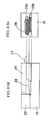
- Figs. 3(a) and 3 (b) are schematic configurations showing an example of a standard optical fiber array of the present invention that has one level of coated fiber, Fig. 3(a) is a front view, and Fig. 3(b) is a right side view.
- Figs. 4 (a) and 4 (b) are schematic configurations showing an example of a half-pitched optical fiber array of the present invention that has two levels of coated fibers, Fig. 4(a) is a front view, and Fig. 4(b) is a right side view.
- Figs. 5(a) and 5(b) are schematic configurations showing another example of a half-pitched optical fiber array of the present invention that has two levels of coated fibers, Fig. 5(a) is a front view, and Fig. 5(b) is a right side view.
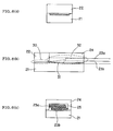
- Figs. 6(a), 6(b), and 6(c) are schematic configurations showing an example of using two kinds of adhesives in an optical fiber array of the present invention
- Fig. 6(a) is a left side view
- Fig. 6(b) is a front view
- Fig. 6(c) is a right side view.
- Fig. 7 is a schematic diagram showing still another embodiment of an irradiation method in an optical fiber array of the present invention.
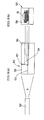
- Figs. 8(a) and 8(b) are schematic diagrams showing another embodiment of an irradiation method in an optical fiber array of the present invention, Fig. 8(a) is a front view, and Fig. 8(b) is a right view.
- Fig. 9 is a front view showing an example of a conventional half-pitched optical fiber array.
- Figs. 1 and 2 are schematic diagrams each showing an embodiment of an irradiation method in an optical fiber array of the present invention.
- the optical fiber array 7 comprises a lower substrate 1 having a V-groove formed on a surface thereof, a fiber presser substrate 3 that is located above the V-groove of the lower substrate 1 and presses an uncoated (bare) optical fiber 2 on the V-groove, and a coated fiber housing substrate 5 for housing a coated fiber 4, the optical fiber array which is constructed by inserting an optical fiber from a coat housing groove 6 formed in the coated fiber housing substrate 5, and aligning the bare optical fiber 2 on the V-groove.
- a ultraviolet hardening-type adhesive is injected with using a capillary action into gaps between the upper substrate (the fiber presser substrate 3 and coated fiber housing substrate 5), lower substrate 1, and optical fiber (the bare optical fiber 2 and coated optical fiber 4).
- a ultraviolet curing unit 8 is provided on a extension line of an optical fiber axis, that is, the extension line of the optical fiber axis that is a line in front of (in the left to the drawing of) the bare optical fiber 2.
- Ultraviolet rays A are applied from this ultraviolet-curing unit 8 toward the bare optical fiber 2 aligned on the V-groove to harden the adhesive.
- the ultraviolet rays A when the ultraviolet rays A are applied from on the extension line of the optical fiber axis toward the optical fiber, the ultraviolet rays A pass through the optical fiber array 7.
- Hardening of the ultraviolet hardening-type adhesive sequentially proceeds from a part of the bare optical fiber 2 on the V-groove to a part of the coated optical fiber 4. In this case, even if hardening-shrinkage of the adhesive arises, the unhardened adhesive which exists in the part after the shrunk part is supplied to the shrunk part. Therefore, hardening of the adhesive proceeds from the front part (a front end face of the bare optical fiber 2) toward the coated optical fiber 4 (the rear part) without distortion.
- this effect occurs not only in a V-groove portion of the optical fiber array but also in a coat housing groove part housing the coated optical fiber.
- a blind 9 prevents the ultraviolet rays from being applied to the optical fiber array 7 from above the optical fiber array 7.
- the invention includes such cases where the ultraviolet rays are applied sufficiently parallel to the optical fiber axis to achieve this desired effect.
- Figs. 3(a) and 3 (b) are schematic configurations showing an example of a standard optical fiber array of the present invention that has one level of coated fiber, Fig. 3(a) is a front view, and Fig. 3(b) is a right side view.
- Figs. 4(a) and 4 (b) are schematic configurations showing an example of a half-pitched optical fiber array of the present invention that has two levels of coated fibers, Fig. 4(a) is a front view, and Fig. 4(b) is a right side view.
- Figs. 5(a) and 5(b) are schematic configurations showing another example of a half-pitched optical fiber array of the present invention that has two levels of coated fibers, Fig. 5(a) is a front view, and Fig. 5(b) is a right side view.
- an optical fiber array 20 comprises a lower substrate 21 having a V-groove formed on a surface thereof, a fiber presser substrate 22 that is located above the V-groove of the lower substrate 21 and presses an uncoated (bare) optical fiber on the V-groove, and a coated fiber housing substrate 24 for pressing a coated optical fiber 23.
- the coated optical fiber 23 is inserted from a coated housing groove 25 formed in the coated fiber housing substrate 24, and the bare optical fiber that is an end portion of the fiber 23 is aligned on the V-groove.
- an adhesive is injected into gaps between the fiber presser substrate 22 and coated fiber housing substrate 24, which construct an upper substrate, the lower substrate 21, and bare optical fiber and coated optical fiber 23. Furthermore, as described above, the adhesive is hardened by being irradiated with ultraviolet rays, and the optical fiber array 20 is completed.
- the adhesive inflow groove portion (hole portion) 26 is provided in a part of the coated housing groove 25 that becomes a supply source of the adhesive in the rear portion of the optical fiber array 20. It is preferable that the direction of the adhesive being supplied, that is, the direction of the groove port 26 is in parallel to the direction of the ultraviolet rays being applied.
- the reason why such a adhesive inflow groove portion 26 is provided in the coated housing groove 25 is that peeling and the like remarkably arise in this part of the coated housing groove 25 where a large amount of adhesive exists. Even if the hardening shrinkage arises in a V-groove portion (including an upper surface portion of the V-groove), the adhesive exists only in the space of the gap between the V-groove and optical fiber, and hence a small amount of adhesive can be supplied. On the other hand, the coat-housing groove 25 has a large space and needs a large amount of adhesive to be supplied, and hence it is effective to provide such an adhesive inflow groove portion 26.
- coated optical fibers 23a and 23b are inserted from the coated housing groove 25 formed in the coated fiber housing substrate 24 with being piled in two levels.
- the upper and lower fibers are aligned alternately on the V-groove. Nevertheless, as described above, the tapered portion 28 of the fiber becomes necessary because of piling the coated optical fibers 23a and 23b in two levels. Therefore, an amount of the adhesive becomes particularly large.
- the adhesive inflow groove portion 26 is a space provided above the two levels of coated optical fibers 23a and 23b by enlarging the coated housing groove 25.
- the adhesive inflow groove portion 26 is provided in an inner side portion of the coat-housing groove 25.
- the amount of the adhesive in the coated housing groove portion is particularly large in comparison with the amount of the adhesive in the V-groove portion (including an upper surface of the V-groove).
- an adhesive for fixing the fiber on the V-groove fulfils the following requirements:
- the adhesive in the coated housing groove portion is required to fulfil the following requirements:
- an adhesive that is hard in some degree is required in the V-groove portion and an adhesive that is soft in some degree is required in the coated housing groove portion.
- two kinds of adhesives that is, a first adhesive 30 for bonding the upper substrate (fiber presser substrate) 22 and V-groove portion of the lower substrate 21 and a second adhesive 32 for bonding the coated optical fibers 23a and 23b between the coated fiber housing substrate 24 and a coated optical fiber supporting portion 31 of the lower substrate 21 are used as adhesives.
- a first adhesive 30 for bonding the upper substrate (fiber presser substrate) 22 and V-groove portion of the lower substrate 21 and a second adhesive 32 for bonding the coated optical fibers 23a and 23b between the coated fiber housing substrate 24 and a coated optical fiber supporting portion 31 of the lower substrate 21 are used as adhesives.
- Young's moduli that is, an adhesive that has a Young's modulus that is larger than that of the second adhesive is used as the first adhesive.
- the kind of the adhesive for the adhesion of the fiber presser substrate 22 and V-groove portion is different from the kind of the adhesive for the adhesion of the coated fiber housing substrate 24 and coated optical fiber supporting portion 31.
- the first adhesive 30 having a large Young's modulus (hard) is used for the former adhesion and the second adhesive 32 having a Young's modulus smaller (soft) than that of the first adhesive 30 is used for the latter adhesion. Therefore, since the second adhesive 32 that is used in large quantities has a small Young's modulus, the hardening shrinkage is not so large. In addition, since the second adhesive 32 is soft, the residual stress is small.
- the first adhesive 30 is hard and has large hardening-shrinkage, filled-amount is small, and hence, similarly, the residual stress is not large, and hence there is no problem.
- an epoxy adhesive is preferable as the first adhesive 30. Since the epoxy adhesive has large adhesive strength and high weather resistance, the epoxy adhesive fulfils the above requirements. On the other hand, an adhesive fulfilling the above requirements is selected among acrylic or silicon adhesives and is used as the second adhesive 32.
- the Young's modulus of the first adhesive is 2-40 kgf/mm 2 and the Young's modulus of the second adhesive is 0.2-2 kgf/mm 2 .
- the upper substrate and lower substrate that form the optical fiber array according to the present invention are composed of materials transmitting light, and for example, glass material or plastic material can be used.
- This epoxy resin adhesive has the Young's modulus of 7.6 kgf/mm 2 , hardness of 86 (Shore D hardness), and a hardening shrinkage rate of 1.88%, and is a low Young's modulus and standard hardness among the epoxy resins.
- the epoxy resin adhesive was applied from the rear portion (the right to the drawing) of the optical fiber array 40. Furthermore, after confirming that the adhesive reached an end portion (the left to the drawing) of the optical fiber array 40, ultraviolet rays were applied.
- a ultraviolet curing unit 41 was provided on an extension line of an optical fiber axis, that is, on the extension line of the optical fiber axis in front of (the left to the drawing of) the optical fiber array 40 so as to avoid the stress caused by the hardening shrinkage. Then, ultraviolet rays were applied from the ultraviolet curing unit 41 to the optical fiber array to harden the adhesive.
- the luminous energy of the ultraviolet rays was 50 mW, and irradiation time was 3 minutes.
- this product (the standard optical fiber array) is examined by a high-temperature/high-humidity test under the conditions of 90%, 75°C, and two weeks, the degree of peeling progressing was good in comparison with a product made by applying ultraviolet rays from above the fiber array.
- an adhesive inflow groove portion 51 was provided as shown in Fig. 8(b).
- the same epoxy resin adhesive as that in the first embodiment was used in a V-groove portion 53 of the half-pitched optical fiber array 50, and a denatured acrylate adhesive having the Young's modulus of 0.58 kgf/mm 2 , hardness of 85 (Shore A hardness), and hardening shrinkage rate of 6.1% was used in a coat housing groove portion 54.
- This denatured acrylate adhesive is an elastic adhesive, and has the Young's modulus and hardness that are considerably low, and hence is a so-called soft adhesive.
- the epoxy resin adhesive was applied to the V-groove portion 53 from the front (the left to the Fig. 8(a)) of the half-pitched optical fiber array 50. Then, the adhesive was made with using the capillary action to permeate into the inside of the V-groove. After confirming that the epoxy resin adhesive pervaded the entire V-groove portion 53, similarly to the first embodiment, ultraviolet rays were applied with an ultraviolet curing unit 52. The luminous energy and irradiation time of the ultraviolet rays was the same as those in the first embodiment.
- the denatured acrylate adhesive was applied from the rear portion (the right to Fig. 8 (a)) of the half-pitched optical fiber array 50.
- the denatured acrylate adhesive could pervade to an end portion of the coated housing groove 54 (or a rear end portion of the V-groove portion 53) without convoluting air.
- ultraviolet rays were applied from the ultraviolet curing unit 52 to the half-pitched optical fiber array 50 to sequentially harden the denatured acrylate adhesive in the coated housing groove portion 54.
- this product (the half-pitched optical fiber array) is examined by a high-temperature/high-humidity test under the conditions of 90%, 75°C, and two weeks, the degree of peeling progressing was good in comparison with a product made by applying ultraviolet rays from above the fiber array.
- the present invention can provide an optical fiber array, which has no loss and excellent long-term reliability by suppressing the residual stress in the optical fiber array as much as possible at the time of hardening an adhesive, and a production method thereof.
Landscapes
- Physics & Mathematics (AREA)
- General Physics & Mathematics (AREA)
- Optics & Photonics (AREA)
- Mechanical Coupling Of Light Guides (AREA)
Applications Claiming Priority (4)
| Application Number | Priority Date | Filing Date | Title |
|---|---|---|---|
| JP7065798 | 1998-03-19 | ||
| JP7065798 | 1998-03-19 | ||
| JP5453599 | 1999-03-02 | ||
| JP11054535A JPH11326704A (ja) | 1998-03-19 | 1999-03-02 | 光ファイバ―アレイ及びその製造方法 |
Publications (1)
| Publication Number | Publication Date |
|---|---|
| EP0943941A1 true EP0943941A1 (de) | 1999-09-22 |
Family
ID=26395299
Family Applications (1)
| Application Number | Title | Priority Date | Filing Date |
|---|---|---|---|
| EP99302051A Withdrawn EP0943941A1 (de) | 1998-03-19 | 1999-03-17 | Optische Fasermatrix und Verfahren zur Herstellung dazu |
Country Status (3)
| Country | Link |
|---|---|
| US (1) | US6304708B1 (de) |
| EP (1) | EP0943941A1 (de) |
| JP (1) | JPH11326704A (de) |
Cited By (9)
| Publication number | Priority date | Publication date | Assignee | Title |
|---|---|---|---|---|
| WO2002031554A1 (en) * | 2000-10-12 | 2002-04-18 | Ngk Insulators,Ltd. | Optical fiber array and method of manufacturing the array |
| WO2004057396A1 (ja) * | 2002-12-20 | 2004-07-08 | Ngk Insulators, Ltd. | 光デバイス |
| EP1336882A3 (de) * | 2002-02-14 | 2004-11-17 | Sumitomo Electric Industries, Ltd. | Faseroptisches Array |
| US7123798B2 (en) | 2002-03-29 | 2006-10-17 | Ngk Insulators, Ltd. | Optical device and method of producing the same |
| US7195402B2 (en) | 2002-12-20 | 2007-03-27 | Ngk Insulators, Ltd. | Optical device |
| US7308174B2 (en) | 2002-12-20 | 2007-12-11 | Ngk Insulators, Ltd. | Optical device including a filter member for dividing a portion of signal light |
| US7321703B2 (en) | 2002-12-20 | 2008-01-22 | Ngk Insulators, Ltd. | Optical device |
| US7324729B2 (en) | 2003-06-02 | 2008-01-29 | Ngk Insulators, Ltd. | Optical device |
| US11366304B2 (en) | 2018-04-26 | 2022-06-21 | Olympus Corporation | Optical module for endoscope, endoscope, and manufacturing method of optical module for endoscope |
Families Citing this family (19)
| Publication number | Priority date | Publication date | Assignee | Title |
|---|---|---|---|---|
| US20030142945A1 (en) * | 2002-01-28 | 2003-07-31 | Dallas Joseph L. | Method and system for attaching one or more optical fibers to a retaining device |
| US6676305B2 (en) | 2002-01-28 | 2004-01-13 | Coviant, Inc. | Apparatus and method of aligning optical fibers to optical devices |
| KR100446505B1 (ko) | 2002-02-02 | 2004-09-04 | 삼성전자주식회사 | 트리 구조의 홈들을 구비한 블록과 이를 이용한 다심광섬유 블록 및 그 정렬 방법 |
| US20030161595A1 (en) * | 2002-02-27 | 2003-08-28 | Dallas Joseph L. | Method of bonding optical devices |
| JP2004109778A (ja) | 2002-09-20 | 2004-04-08 | Sumitomo Metal Mining Co Ltd | 光ファイバアレイとその製造方法 |
| KR20040032287A (ko) * | 2002-10-09 | 2004-04-17 | 주식회사 세미텔 | 평면 하부기판을 갖는 광섬유 어레이 블록 조립체와 그 제조방법 |
| US7076136B1 (en) * | 2003-03-11 | 2006-07-11 | Inplane Photonics, Inc. | Method of attaching optical fibers to integrated optic chips that excludes all adhesive from the optical path |
| JP4301245B2 (ja) * | 2003-11-17 | 2009-07-22 | 住友金属鉱山株式会社 | 光ファイバアレイ |
| JP2006065943A (ja) | 2004-08-26 | 2006-03-09 | Hitachi Media Electoronics Co Ltd | 光ピックアップ装置およびその製造方法 |
| JP2008020741A (ja) * | 2006-07-13 | 2008-01-31 | Mitsubishi Cable Ind Ltd | 光ファイバの端末構造 |
| JP5743212B2 (ja) * | 2011-09-09 | 2015-07-01 | 日立金属株式会社 | 光電変換モジュール |
| US9140872B2 (en) * | 2013-09-17 | 2015-09-22 | Panduit Corp. | Hydra cable assembly and components thereof |
| US11573377B2 (en) * | 2015-10-12 | 2023-02-07 | 3M Innovative Properties Company | Optical waveguide positioning feature in a multiple waveguides connector |
| JP6763182B2 (ja) * | 2016-04-01 | 2020-09-30 | 日立金属株式会社 | 光ファイバ固定構造及び光ファイバ固定方法 |
| JP2018180197A (ja) * | 2017-04-10 | 2018-11-15 | 住友電気工業株式会社 | 光部品 |
| CN110673267A (zh) * | 2019-09-27 | 2020-01-10 | 深圳活力激光技术有限公司 | 一种光纤阵列排布的装置及方法 |
| JP7521458B2 (ja) * | 2021-03-04 | 2024-07-24 | 住友電気工業株式会社 | 光コネクタケーブル |
| JP2024023002A (ja) * | 2022-08-08 | 2024-02-21 | 住友電気工業株式会社 | 光モジュール及び光モジュールの製造方法 |
| CN115437073B (zh) * | 2022-09-22 | 2024-08-02 | 成都宸雄科技有限公司 | 一种耐水煮光纤阵列的制作方法 |
Citations (8)
| Publication number | Priority date | Publication date | Assignee | Title |
|---|---|---|---|---|
| US4378954A (en) * | 1979-01-18 | 1983-04-05 | Itt Industries, Inc. | Method of making optical fiber termination |
| JPS63204204A (ja) * | 1987-02-20 | 1988-08-23 | Nec Corp | 光フアイバコネクタフエル−ル |
| US4784457A (en) * | 1986-03-11 | 1988-11-15 | Siemens Aktiengesellschaft | Connector device for light waveguides held with an adhesive |
| EP0564207A2 (de) * | 1992-03-30 | 1993-10-06 | Ngk Insulators, Ltd. | Faseroptischer Stecker |
| EP0573288A2 (de) * | 1992-06-03 | 1993-12-08 | Ngk Insulators, Ltd. | Faseroptischer Stecker und seine Herstellungsmethode |
| EP0611142A1 (de) * | 1993-02-12 | 1994-08-17 | Ngk Insulators, Ltd. | Verfahren zum optischen Koppeln eines Faserarrays mit einem entgegenstehenden Baustein |
| EP0624808A1 (de) * | 1993-03-29 | 1994-11-17 | Sumitomo Electric Industries, Ltd. | Optischer Stecker |
| JPH07248424A (ja) * | 1994-03-11 | 1995-09-26 | Nippon Sheet Glass Co Ltd | 光ファイバアレイおよび光デバイス |
Family Cites Families (5)
| Publication number | Priority date | Publication date | Assignee | Title |
|---|---|---|---|---|
| JPH03240005A (ja) * | 1990-02-19 | 1991-10-25 | Brother Ind Ltd | 光導波路アレイ |
| JP3333843B2 (ja) * | 1993-03-11 | 2002-10-15 | 日本碍子株式会社 | 光コリメータアレイの光軸合わせ方法 |
| CA2127861C (en) * | 1993-07-14 | 2004-09-21 | Shinji Ishikawa | Coupling structure of optical fibers and optical waveguides |
| JPH09120014A (ja) * | 1995-08-24 | 1997-05-06 | Ngk Insulators Ltd | 光ファイバアレイ |
| US6160937A (en) * | 1998-03-20 | 2000-12-12 | Ngk Insulators, Ltd. | Optical fiber array |
-
1999
- 1999-03-02 JP JP11054535A patent/JPH11326704A/ja active Pending
- 1999-03-05 US US09/262,822 patent/US6304708B1/en not_active Expired - Lifetime
- 1999-03-17 EP EP99302051A patent/EP0943941A1/de not_active Withdrawn
Patent Citations (8)
| Publication number | Priority date | Publication date | Assignee | Title |
|---|---|---|---|---|
| US4378954A (en) * | 1979-01-18 | 1983-04-05 | Itt Industries, Inc. | Method of making optical fiber termination |
| US4784457A (en) * | 1986-03-11 | 1988-11-15 | Siemens Aktiengesellschaft | Connector device for light waveguides held with an adhesive |
| JPS63204204A (ja) * | 1987-02-20 | 1988-08-23 | Nec Corp | 光フアイバコネクタフエル−ル |
| EP0564207A2 (de) * | 1992-03-30 | 1993-10-06 | Ngk Insulators, Ltd. | Faseroptischer Stecker |
| EP0573288A2 (de) * | 1992-06-03 | 1993-12-08 | Ngk Insulators, Ltd. | Faseroptischer Stecker und seine Herstellungsmethode |
| EP0611142A1 (de) * | 1993-02-12 | 1994-08-17 | Ngk Insulators, Ltd. | Verfahren zum optischen Koppeln eines Faserarrays mit einem entgegenstehenden Baustein |
| EP0624808A1 (de) * | 1993-03-29 | 1994-11-17 | Sumitomo Electric Industries, Ltd. | Optischer Stecker |
| JPH07248424A (ja) * | 1994-03-11 | 1995-09-26 | Nippon Sheet Glass Co Ltd | 光ファイバアレイおよび光デバイス |
Non-Patent Citations (3)
| Title |
|---|
| ISABELLE RERISSIN-FABERT ET AL.: "Nondestructive Evaluation of Materials Using an Inserted Piezoelectric Sensor-Corralation with Hardness Mesurements", IEEE TRANSACTION ON ULTRASONICS, FERROELECTRICS, AND FREQUNECY CONTROL, vol. 42, no. 4, 4 July 1995 (1995-07-04), pages 641 - 648, XP000521146 * |
| J. GUBICZA ET AL.: "Determination of the hardness and elastic modulus from continuous Vickers indentation testing", JOURNAL OF MATERIALS SCIENCE, vol. 31, 1996, pages 3109 - 3114, XP009086112 * |
| PATENT ABSTRACTS OF JAPAN vol. 012, no. 492 22 December 1988 (1988-12-22) * |
Cited By (10)
| Publication number | Priority date | Publication date | Assignee | Title |
|---|---|---|---|---|
| WO2002031554A1 (en) * | 2000-10-12 | 2002-04-18 | Ngk Insulators,Ltd. | Optical fiber array and method of manufacturing the array |
| EP1336882A3 (de) * | 2002-02-14 | 2004-11-17 | Sumitomo Electric Industries, Ltd. | Faseroptisches Array |
| US7021842B2 (en) | 2002-02-14 | 2006-04-04 | Sumitomo Electric Industries, Ltd. | Optical fiber array |
| US7123798B2 (en) | 2002-03-29 | 2006-10-17 | Ngk Insulators, Ltd. | Optical device and method of producing the same |
| WO2004057396A1 (ja) * | 2002-12-20 | 2004-07-08 | Ngk Insulators, Ltd. | 光デバイス |
| US7195402B2 (en) | 2002-12-20 | 2007-03-27 | Ngk Insulators, Ltd. | Optical device |
| US7308174B2 (en) | 2002-12-20 | 2007-12-11 | Ngk Insulators, Ltd. | Optical device including a filter member for dividing a portion of signal light |
| US7321703B2 (en) | 2002-12-20 | 2008-01-22 | Ngk Insulators, Ltd. | Optical device |
| US7324729B2 (en) | 2003-06-02 | 2008-01-29 | Ngk Insulators, Ltd. | Optical device |
| US11366304B2 (en) | 2018-04-26 | 2022-06-21 | Olympus Corporation | Optical module for endoscope, endoscope, and manufacturing method of optical module for endoscope |
Also Published As
| Publication number | Publication date |
|---|---|
| JPH11326704A (ja) | 1999-11-26 |
| US6304708B1 (en) | 2001-10-16 |
Similar Documents
| Publication | Publication Date | Title |
|---|---|---|
| US6304708B1 (en) | Optical fiber array and production method thereof | |
| US5422971A (en) | Optical fiber connector using adhesive | |
| US5420952A (en) | Optical connector employing two different types of adhesives | |
| US10705299B2 (en) | Ferrule structure, ferrule structure with fiber, and method for manufacturing ferrule structure with fiber | |
| JP2001033664A (ja) | 光ファイバブロック | |
| EP1139131B1 (de) | Optische Fasermatrixanordnung | |
| US6798969B2 (en) | Fiber array, method for fabricating the same and optical device using the fiber array | |
| JPWO2023199632A5 (de) | ||
| CN118355304A (zh) | 一种插芯、光连接器以及光连接器的制造方法 | |
| US6160937A (en) | Optical fiber array | |
| CN101416088B (zh) | 光缆模块 | |
| JP3402007B2 (ja) | 光導波路デバイスの製造方法 | |
| US20030007770A1 (en) | Optical fiber array and process for production thereof | |
| JPH0954227A (ja) | 光実装用成形基板及びその製造方法 | |
| JP2007127878A (ja) | 光導波路接続構造 | |
| JP2000329971A (ja) | 光ファイバーアレイ | |
| JP3798149B2 (ja) | 光ファイババンドルとその製造方法 | |
| JPH07253522A (ja) | 光ファイバ端末部、その製造方法及び端末部と光デバイスとの接続構造 | |
| EP0943942A2 (de) | Optische Faseranordnung | |
| JPH09133840A (ja) | 多心光コネクタとその製造方法 | |
| JPH0694945A (ja) | 光ファイバ用コネクタおよびその製造方法 | |
| JP2000009958A (ja) | 光ファイバコネクタ及び光結合素子 | |
| JPH0854537A (ja) | 光ファイバ及び光導波路モジュールの結合体及び結合方法 | |
| JPH11305058A (ja) | 光ファイバアレイ | |
| JP2000137133A (ja) | 光ファイバアレイ |
Legal Events
| Date | Code | Title | Description |
|---|---|---|---|
| PUAI | Public reference made under article 153(3) epc to a published international application that has entered the european phase |
Free format text: ORIGINAL CODE: 0009012 |
|
| AK | Designated contracting states |
Kind code of ref document: A1 Designated state(s): DE FR GB IT |
|
| AX | Request for extension of the european patent |
Free format text: AL;LT;LV;MK;RO;SI |
|
| 17P | Request for examination filed |
Effective date: 19990825 |
|
| AKX | Designation fees paid |
Free format text: DE FR GB IT |
|
| 17Q | First examination report despatched |
Effective date: 20040525 |
|
| STAA | Information on the status of an ep patent application or granted ep patent |
Free format text: STATUS: THE APPLICATION IS DEEMED TO BE WITHDRAWN |
|
| 18D | Application deemed to be withdrawn |
Effective date: 20071124 |